JP2004347601A - Combustible gas detector having flow sensor container and method for measuring combustible gas - Google Patents
Combustible gas detector having flow sensor container and method for measuring combustible gas Download PDFInfo
- Publication number
- JP2004347601A JP2004347601A JP2004149866A JP2004149866A JP2004347601A JP 2004347601 A JP2004347601 A JP 2004347601A JP 2004149866 A JP2004149866 A JP 2004149866A JP 2004149866 A JP2004149866 A JP 2004149866A JP 2004347601 A JP2004347601 A JP 2004347601A
- Authority
- JP
- Japan
- Prior art keywords
- gas
- chamber
- sensor
- flow
- sample
- Prior art date
- Legal status (The legal status is an assumption and is not a legal conclusion. Google has not performed a legal analysis and makes no representation as to the accuracy of the status listed.)
- Granted
Links
Images



Classifications
-
- G—PHYSICS
- G01—MEASURING; TESTING
- G01N—INVESTIGATING OR ANALYSING MATERIALS BY DETERMINING THEIR CHEMICAL OR PHYSICAL PROPERTIES
- G01N27/00—Investigating or analysing materials by the use of electric, electrochemical, or magnetic means
- G01N27/02—Investigating or analysing materials by the use of electric, electrochemical, or magnetic means by investigating impedance
- G01N27/04—Investigating or analysing materials by the use of electric, electrochemical, or magnetic means by investigating impedance by investigating resistance
- G01N27/14—Investigating or analysing materials by the use of electric, electrochemical, or magnetic means by investigating impedance by investigating resistance of an electrically-heated body in dependence upon change of temperature
- G01N27/16—Investigating or analysing materials by the use of electric, electrochemical, or magnetic means by investigating impedance by investigating resistance of an electrically-heated body in dependence upon change of temperature caused by burning or catalytic oxidation of surrounding material to be tested, e.g. of gas
-
- G—PHYSICS
- G01—MEASURING; TESTING
- G01N—INVESTIGATING OR ANALYSING MATERIALS BY DETERMINING THEIR CHEMICAL OR PHYSICAL PROPERTIES
- G01N1/00—Sampling; Preparing specimens for investigation
- G01N1/02—Devices for withdrawing samples
- G01N1/22—Devices for withdrawing samples in the gaseous state
- G01N1/24—Suction devices
Landscapes
- Chemical & Material Sciences (AREA)
- Chemical Kinetics & Catalysis (AREA)
- Electrochemistry (AREA)
- Physics & Mathematics (AREA)
- Health & Medical Sciences (AREA)
- Life Sciences & Earth Sciences (AREA)
- Analytical Chemistry (AREA)
- Biochemistry (AREA)
- General Health & Medical Sciences (AREA)
- General Physics & Mathematics (AREA)
- Immunology (AREA)
- Pathology (AREA)
- Investigating Or Analyzing Materials By The Use Of Electric Means (AREA)
Abstract
【課題】 ガス検出器のゼロ校正及び感度校正するための方法及び装置を提供する。
【解決手段】 触媒センサ(12)を使用して可燃性ガスを測定するための装置(10)及び方法は、周囲ガスのボリューム(30)から隔離された流通チャンバ(16)内に触媒センサを収納することと、周囲ガスの試料を流通チャンバ内へ周期的に引き込むこと(60)と、触媒センサ及び流通チャンバで周囲ガスの試料中の可燃性ガスを、例えば、本質的に完全燃焼が完了するまで燃焼させることと、触媒チャンバで試料を燃焼させている間、周囲ガスの試料抽出の中断と同時に触媒センサの複数の出力信号を測定すること(62)とを含む。
【選択図】 図1PROBLEM TO BE SOLVED: To provide a method and an apparatus for zero calibration and sensitivity calibration of a gas detector.
An apparatus (10) and method for measuring flammable gas using a catalyst sensor (12) comprises a catalyst sensor in a flow chamber (16) isolated from a volume of ambient gas (30). Storing and periodically drawing (60) a sample of the ambient gas into the flow chamber; and combusting the combustible gas in the sample of the ambient gas with the catalyst sensor and the flow chamber, eg, essentially complete combustion. And measuring a plurality of output signals of the catalyst sensor simultaneously with interrupting sampling of the ambient gas while burning the sample in the catalyst chamber (62).
[Selection diagram] Fig. 1
Description
本発明は、流通センサ容器を有する触媒可燃性ガス検出器に関し、より具体的にはガス検出器のゼロ校正及び感度校正するための方法及び装置に関する。 The present invention relates to a catalytic combustible gas detector having a flow sensor container, and more particularly, to a method and apparatus for zero calibration and sensitivity calibration of a gas detector.
可燃性ガス及び蒸気(ここではまとめて「可燃性ガス」又は「可燃性物質」と呼ぶ)の有無を検出し、その濃度を測定するための周知の方法はいくつかある。そのような方法の1つにおいては、触媒による燃焼の間に熱発生の速度を実際に測定することに基づいて可燃性ガスが検出される。可燃性ガス検出器は、触媒センサにおいてガス試料を燃焼させることにより可燃性ガスを検出し、測定する。触媒による燃焼はセンサの加熱される多孔質基板、例えば、触媒を含浸させたシリカ又はアルミナの表面で起こる。その結果起こる基板の温度の上昇は触媒による燃焼の間の熱発生速度に比例し、埋め込み抵抗温度検出器(RTD)の抵抗変化を感知することにより電子的に測定される。 There are several well-known methods for detecting the presence or absence of combustible gases and vapors (collectively referred to herein as "flammable gases" or "flammable materials") and measuring their concentrations. In one such method, combustible gas is detected based on actually measuring the rate of heat generation during combustion by the catalyst. The combustible gas detector detects and measures a combustible gas by burning a gas sample with a catalyst sensor. Catalytic combustion occurs on the heated porous substrate of the sensor, for example, silica or alumina impregnated with the catalyst. The resulting increase in substrate temperature is proportional to the rate of heat generation during combustion by the catalyst and is measured electronically by sensing the resistance change of an embedded resistance temperature detector (RTD).
周知の種類の触媒可燃性ガス検出器は触媒ビードセンサと、基準ビードと、ホイートストンブリッジとを有する。ビードセンサは、従来、小さなビードの形態をとる触媒含浸基板と、RTDと、ビードの本体に埋め込まれたごく小さなプラチナ(Pt)ワイヤコイルとして製造されている加熱装置組み合わせとを含む。通常、基準ビード(補償ビードとも呼ばれる)は、補償ビードが触媒を含浸されていないという点を除いて、加熱装置を伴う触媒含浸ビードに類似している。感知ビード及び基準ビードは、加熱コイルの延長であるPtワイヤにより支持されている。触媒含浸ビード及び基準ビードは多孔性カップ(エンクロージャ)により周囲ガスから遮蔽されていても良い。カップエンクロージャは、周囲ガスを本質的に拡散によってビードに到達させるようにガスを透過する。カップはステンレス鋼の細目金網又はより頑丈な多孔性材料、例えば、焼結セラミックから形成されていても良い。多孔性セラミックカップは検出器構造の爆発防止のための難燃障壁としても機能できるであろう。 Known types of catalytic combustible gas detectors include a catalytic bead sensor, a reference bead, and a Wheatstone bridge. Bead sensors include a catalyst-impregnated substrate, conventionally in the form of a small bead, an RTD, and a heater combination fabricated as a tiny platinum (Pt) wire coil embedded in the body of the bead. Usually, the reference bead (also called the compensating bead) is similar to a catalyst-impregnated bead with a heating device, except that the compensating bead is not impregnated with the catalyst. The sensing and reference beads are supported by Pt wires, which are extensions of the heating coil. The catalyst impregnated bead and the reference bead may be shielded from ambient gas by a porous cup (enclosure). The cup enclosure is permeable to gas so that the surrounding gas reaches the bead essentially by diffusion. The cup may be formed from a stainless steel mesh or a more robust porous material, such as a sintered ceramic. The porous ceramic cup could also serve as a fire retardant barrier for the detector structure to prevent explosion.
従来の触媒センサは、周囲環境からビードに向かって拡散する可燃性ガスの絶え間のない流入にさらされる。試料ガスは対流によってもビードに到達する。この場合のセンサの周囲のガス速度の変化はセンサの偽読み値を誘発するであろう。ガス速度の変化に起因する測定誤差を減少させようとする以前の試みは、センサ感度を低下させ、センサの応答時間を長くしようとするものであった。 Conventional catalyst sensors are exposed to a constant influx of combustible gas that diffuses from the surrounding environment toward the bead. The sample gas also reaches the bead by convection. A change in gas velocity around the sensor in this case will trigger a false reading of the sensor. Previous attempts to reduce measurement errors due to changes in gas velocity have attempted to reduce sensor sensitivity and increase sensor response time.
従来のセンサの触媒感知ビード及び基準ビードは、通常、平衡ホイートストンブリッジ回路の抵抗ショルダとして接続されている。感知ビードで燃焼加熱が起こると、その結果、感知ビードに埋め込まれたRTDの抵抗は基準ビードRTDの抵抗に関して変化して、ブリッジ不均衡を発生させる。 The catalyst sensing bead and reference bead of conventional sensors are typically connected as resistive shoulders in a balanced Wheatstone bridge circuit. When combustion heating occurs in the sense bead, the resistance of the RTD embedded in the sense bead changes with respect to the resistance of the reference bead RTD, causing a bridge imbalance.
ブリッジの出力電圧は感知ビードRTDと基準ビードRTDの抵抗の不均衡を示し、可燃性ガスの濃度を取り出す元になる信号として出力される。しかし、従来の検出器におけるブリッジ不均衡は、ビードのエージング、周囲温度の変化などのバックグラウンドの変化、不燃性ガス混合物の組成、及び水分濃度の相違によるセンサビードの付近の放射線吸収を含む、感知ビードにおける触媒による燃焼以外の要因によって影響を受ける可能性がある。これらの他の要因は検出器の低い検出限界を著しく大きく上昇させ、検出器の応答を燃焼ガスに対する定格検出レベル又は範囲から逸脱させてしまう。 The output voltage of the bridge indicates an imbalance between the resistance of the sensing bead RTD and the resistance of the reference bead RTD and is output as a signal from which the concentration of combustible gas is extracted. However, bridge imbalances in conventional detectors include aging of the beads, changes in background such as changes in ambient temperature, the composition of the non-flammable gas mixture, and radiation absorption near the sensor beads due to differences in moisture concentration. It may be affected by factors other than catalytic combustion in the bead. These other factors can significantly increase the low detection limit of the detector and cause the detector response to deviate from the rated detection level or range for combustion gases.
従来の触媒検出器の可燃性ガスに対する感度は、センサビードにおける触媒の「無力化」によっても低減されるであろう。無力化されると、センサの可燃性物質に対する感度は低下する。触媒センサ、特に、火災及び爆発を防止するために採用される低爆発限界(LEL)検出器などの、危機的用途で使用される触媒センサの場合には、可燃性ガスに対する感度の低下及びセンサドリフトは厄介な問題である。 The sensitivity of conventional catalyst detectors to combustible gases will also be reduced by "disabling" the catalyst in the sensor bead. When disabled, the sensitivity of the sensor to combustible materials decreases. Catalytic sensors, particularly those used in critical applications, such as low explosion limit (LEL) detectors employed to prevent fires and explosions, have reduced sensitivity to combustible gases and sensors Drift is a tricky problem.
触媒ビードセンサの「無力化」は、従来、ガス試料に濃度がわかっている可燃性物質を直接に適用することにより検出されている。拡散型センサの場合、この手順は相対的に煩雑である。更に、検出器が感度を失ってから、検出器の感度損失が回復されるまでに、例えば、数ヶ月に至るような長い期間が経過してしまうこともある。無力化した検出器は危険なレベルの可燃性物質を検出できない可能性がある。従来の検出器における自動化感度検査又は頻繁に手作業で行われる感度検査は、その実現に極めて高い費用が要求される。 The "disabling" of the catalyst bead sensor is conventionally detected by directly applying a flammable substance having a known concentration to a gas sample. In the case of a diffusion type sensor, this procedure is relatively complicated. Further, a long period of time, for example, several months, may elapse after the detector loses sensitivity and before the loss of sensitivity of the detector is recovered. Disabled detectors may not be able to detect dangerous levels of combustible materials. Automated sensitivity tests on conventional detectors or sensitivity tests that are frequently performed manually require extremely high costs to implement.
従来の触媒ビードセンサでは、あるガス群に対して選択的に感度を向上又は低下させることができ、一般に、これは触媒ビードの特定の温度設定を選択することにより実現される。この温度選択技法は、単一のセンサを使用して、1つの固定された温度で2種類以上の可燃性ガスを含む異なる組成を判別するときには有効ではないであろう。特に、触媒ビードセンサは実際には一酸化炭素(CO)ガスと水素(H2)ガスを判別することができない。通常、COとH2は共にほぼ同じ「低い」触媒温度で触媒による燃焼を開始し、実際にビードの温度設定に基づいてこれらを判別することは不可能である。従って、従来の触媒検出器は、長い期間にわたり可燃性ガスの低い濃度、例えば、500ppm(百万分率)を下回る濃度を測定すること、何年もの期間にわたりドリフトなく安定した「ゼロ」を維持すること、及び可燃性ガスを判別すること、例えば、COとH2を判別することには有効ではないといえるであろう。 In a conventional catalyst bead sensor, the sensitivity can be selectively increased or decreased for a group of gases, which is generally achieved by selecting a particular temperature setting for the catalyst bead. This temperature selection technique would not be effective when using a single sensor to determine different compositions containing more than one flammable gas at one fixed temperature. In particular, the catalyst bead sensor cannot actually distinguish between carbon monoxide (CO) gas and hydrogen (H 2 ) gas. Usually, CO and H 2 is the combustion catalytic starts together at approximately the same "low" catalyst temperature, it is possible to determine them on the basis of the actual bead temperature setting impossible. Thus, conventional catalyst detectors measure low concentrations of combustible gases over long periods of time, for example, concentrations below 500 ppm (parts per million), and maintain a stable "zero" without drift over a period of years. It can be said that it is not effective to perform the determination of the flammable gas, for example, the determination of CO and H 2 .
第1の実施例において、本発明は、触媒センサを使用して可燃性ガスを測定する方法であり、方法は、周囲ガスのボリュームからの触媒センサへのガス拡散を本質的に阻止する流通チャンバ内に触媒センサを収納することと、チャンバ内へ周囲ガスの流れを引き込むことと、チャンバ内へ周囲ガスの試料が引き込まれた後、チャンバ内への周囲ガスの流れを遮断することと、ガス流れの遮断と同時に触媒センサの出力を測定することとを含む。 In a first embodiment, the present invention is a method of measuring combustible gas using a catalytic sensor, the method comprising a flow chamber that essentially prevents gas diffusion from a volume of ambient gas to the catalytic sensor. Enclosing a catalyst sensor therein, drawing ambient gas flow into the chamber, shutting off ambient gas flow into the chamber after a sample of ambient gas is drawn into the chamber, Measuring the output of the catalyst sensor simultaneously with the flow interruption.
第1の実施例は、センサを伴うチャンバ内へガス試料を引き込む過程と、繰り返し実行される測定サイクルの中で出力信号の変化を測定する過程とを更に含んでいても良い。更に、第1の実施例は、(チャンバ内へ試料を引き込む前に)以前にセンサチャンバを通って引き込まれ、「呼吸している」ポンプチャンバの中へ「吸い込まれた」ガス試料によってチャンバをパージングする過程と、ポンプ及び/又はセンサチャンバ内に残留している可燃性ガスを燃焼させる過程と、残留している可燃性ガスがほぼ完全に燃焼した後、センサからの基準出力信号を測定する過程と、ポンプの「吸い込み」によって室内からセンサチャンバへ新たなガス試料を引き込む過程と、新たなガス試料を燃焼させている間にセンサ出力信号を測定する過程と、新たな試料の燃焼中に測定された出力信号と基準出力信号との差によって可燃性ガスの濃度を判定する過程とを含んでいても良い。 The first embodiment may further include drawing a gas sample into the chamber with the sensor and measuring a change in the output signal in a repeatedly performed measurement cycle. In addition, the first embodiment illustrates that a gas sample that has been previously drawn through the sensor chamber (prior to drawing the sample into the chamber) and that has been “inhaled” into the “breathing” pump chamber can be used. Purging, burning the combustible gas remaining in the pump and / or the sensor chamber, and measuring the reference output signal from the sensor after the remaining combustible gas has almost completely burned. The process, drawing a new gas sample from the room into the sensor chamber by "sucking" the pump, measuring the sensor output signal while burning the new gas sample, and Determining the concentration of the flammable gas based on the difference between the measured output signal and the reference output signal.
更に、第1の実施例は、試料がチャンバ内へ引き込まれた後に始まり、試料の燃焼中は継続する周期の間に出力信号の測定を繰り返すことと、複数のセンサ出力測定値を通して試料燃焼のダイナミクスを解析することと、試料中の複数の可燃性ガスのうちの少なくとも1つの可燃性ガスの濃度を判定することとを含んでいても良い。 Further, the first embodiment begins after the sample has been drawn into the chamber and repeats the measurement of the output signal during a continuous period during sample combustion, and the measurement of sample combustion through multiple sensor output measurements. The method may include analyzing the dynamics and determining a concentration of at least one combustible gas of the plurality of combustible gases in the sample.
加えて、第1の実施例は、チャンバから第1のガス試料をパージングし、その後、センサの第1の出力信号を測定する過程と、所定の量の水素によって濃縮された第2のガス試料によってチャンバをパージングする過程と、その後、センサの第2の出力信号を測定する過程と、センサ感度を判定するために第1の出力と第2の出力との差を適用する過程とを含んでいても良い。 In addition, the first embodiment involves purging a first gas sample from a chamber and then measuring a first output signal of the sensor, and a second gas sample enriched by a predetermined amount of hydrogen. Purging the chamber, thereafter measuring a second output signal of the sensor, and applying a difference between the first output and the second output to determine sensor sensitivity. May be.
第2の実施例においては、本発明は、触媒センサを有する検出器を使用して可燃性ガスを測定する方法であり、方法は、触媒センサを周囲ガスから隔離する流通チャンバ内に触媒センサを収納することと、対流により周囲ガスの試料を流通チャンバ内へ引き込むことと、チャンバ内のセンサ、例えば、触媒センサビード自体に加えられたガス試料中の可燃性ガスをほぼ完全に燃焼させることにより検出器を自動的にゼロ化するために、チャンバを通るガスの流れを遮断する及び/又は反転させることと、試料抽出速度の変化と同期させて検出器の少なくとも2つの出力信号を測定することとを含む。 In a second embodiment, the present invention is a method of measuring flammable gas using a detector having a catalyst sensor, the method comprising: placing a catalyst sensor in a flow chamber that isolates the catalyst sensor from ambient gases. Storing, convection draws a sample of the ambient gas into the flow chamber, and detection by burning the flammable gas in the gas sample applied to the sensor, e.g., the catalyst sensor bead itself, in the chamber almost completely Shutting off and / or reversing the flow of gas through the chamber to automatically zero the instrument, measuring at least two output signals of the detector in synchronization with changes in the sample extraction rate; including.
第3の実施例においては、本発明は、周囲ガス混合物中の可燃性物質を検出する検出器であり、検出器は、ガス拡散能力を最小限に抑えた、例えば、内径(ID)が限定された管であり、周囲ガス混合物のボリュームに接続可能である第1の拡散阻止流路に結合されたポートと、第2の拡散阻止流路に結合された第2のポートとを有し、ガスを透過しない流通チャンバと、チャンバの内部に設置された可燃性ガスの触媒型センサと、第2の拡散阻止流路を介してチャンバに空気接続されたガスポンプと、チャンバを通るガスの流れを遮断し且つ/又は交互に変化させるポンプ制御装置とを具備する。更に特定された第2の実施例では、ポンプは前記センサチャンバを介して周囲空気試料をポンプチャンバ内へ吸い込み、ポンプチャンバから周囲ガス試料を吐き出す。第2の実施例においては、第1の拡散阻止流路は10mmから5000mmの範囲の長さ及び0.1mmから3mmの範囲の内径を有する管であっても良い。第2の実施例では、触媒センサのセンサビード及び基準ビードはチャンバを通る対流ガス流に対して対称に配置されている。 In a third embodiment, the invention is a detector for detecting flammable substances in an ambient gas mixture, wherein the detector has a minimal gas diffusion capacity, for example, a limited inner diameter (ID). Tubing, having a port coupled to a first diffusion-blocking channel connectable to a volume of ambient gas mixture, and a second port coupled to a second diffusion-blocking channel. A gas-permeable flow chamber, a flammable gas catalytic sensor installed inside the chamber, a gas pump air-connected to the chamber via a second diffusion blocking channel, and a gas flow through the chamber. A pump control which shuts off and / or alternates. In a second more specific embodiment, the pump draws an ambient air sample into the pump chamber via the sensor chamber and expels an ambient gas sample from the pump chamber. In a second embodiment, the first diffusion blocking channel may be a tube having a length in the range of 10 mm to 5000 mm and an inner diameter in the range of 0.1 mm to 3 mm. In a second embodiment, the sensor bead and the reference bead of the catalyst sensor are symmetrically arranged with respect to the convective gas flow through the chamber.
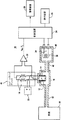
図1は、多孔性エンクロージャ又はその他の保護エンクロージャ14内にあり、流通チャンバ16の内部に収納された可燃性ガスセンサ12を有する可燃性ガス検出器10を示す。この構成においては、保護エンクロージャ14は任意の構造であり、市販の触媒センサではセンサメーカーにより一般に設置されていることから図1に示されている。チャンバ16は周囲から拡散されるガスを透過せず、相当に長い距離、例えば、10mまでの距離を隔てて周囲ガスボリューム30から分離されていても良い。チャンバは拡散制限流路32によりボリューム30に空気接続された試料ガス入口と、排出流路40とを有する。拡散制限流路32は、対流によりガス試料を引き込むことができる一方で、ボリューム30からチャンバ16内へ周囲ガスが拡散することを本質的に阻止する。チャンバ16内にあるセンサ12は、例えば、ホイートストンブリッジ41の抵抗ショルダ18として接続される触媒感知ビード及び基準ビードを有する従来の触媒ビードセンサなどの触媒可燃性物質センサであっても良い。ホイートストンブリッジ41は電源20により給電される。
FIG. 1 shows a
ホイートストンブリッジ41の出力は前置増幅器22により増幅された後、マイクロプロセッサ利用制御装置24により読み取られる。制御装置はブリッジ出力からのデータを電子的に格納するために収集し、そのデータを処理して、ガス試料中に可燃性ガスが存在するか否かを解析するか、又はホイートストンブリッジ41の出力に基づいて可燃性ガスの濃度及び/又は組成を評価する。制御装置はそのデータ処理の結果を液晶表示装置(LCD)などの表示装置26及び警報装置などの検出器インタフェース装置28へ出力する。
The output of the
センサチャンバ16は、可燃性ガスを含んでいる可能性がある部屋、煙突又はその他のボリュームなどの周囲ガスのボリューム30に空気接続されている。チャンバは、周囲ガスがボリューム30から拡散することによりセンサ12に到達するのを防止するように、周囲ガスから隔離されている。拡散制限流路32はチャンバ16をガスボリューム30に接続する。この流路32は、0.1mmから3mmの内径及び10mmから10000mmの長さを有する管であっても良い。特に、拡散制限流路32の寸法は、流路を通過する周囲ガスの拡散速度が試料抽出用ポンプ34により強制的に形成される対流の流速より遅い速度まで減速されるように選択される。流路32は実質的に可燃性ガスが外部ボリューム30から拡散するのを阻止する。拡散ガスがチャンバ16に流入するのを防止することにより、センサが0化されているときに一時的にガス試料から可燃性物質を除去するプロセスが容易になる。拡散ガスの流れを最小にする拡散制限流路32は、センサチャンバ16における炎の逆火を防止するための火炎防止装置としても機能できる。ガス試料は本質的にボリューム30から拡散制限流路32を通ってセンサチャンバ16内へ対流によって流れる。流路32は、周囲ガスの試料がチャンバ16内へ引き込まれるための導管を形成する一方で、チャンバ16をボリューム30の周囲ガスの流れの変化から有効に隔離する。
The
検出器のボリューム30、拡散制限流路32及びセンサチャンバ16はガスポンプ34に直列に空気接続されている。ガスポンプは制御された流量の試料ガスをボリューム30から流路32を経てセンサチャンバ16の中へ引き込む。ポンプは、制御装置24からの制御信号に応答する従来の試料抽出用ポンプ又は「呼吸」ポンプ(図1に示す)であれば良い。呼吸ポンプ34は、制御装置24により制御されるヒータコイル38を収納する密閉ポンプチャンバ36であっても良い。チャンバ36内のガスを加熱、冷却することにより、ガスはポンプチャンバ36から押し出されたり、引き込まれたりする。呼吸ポンプは機械的に単純であり、動作の信頼性が高く、寿命も長い。呼吸ポンプは動く部品を含まず、約500℃までの周囲温度で動作できる。その他の種類の試料抽出用ポンプをポンプ34として採用しても差し支えない。
The
試料が燃焼され、測定されている間、チャンバ16内への試料の流れは遮断される。試料ガス流れの遮断は、ポンプ34を制御することにより、又は例えば、制御装置に接続されたソレノイド弁を採用するなど、チャンバ16に至る迂回ガス流れを制御することにより実現できる。ポンプ34は制御された少量のガス(試料ガス)を「吸入」し、その後、繰り返しサイクルでその試料をパージングする(「吐き出す」)。
While the sample is burning and being measured, the flow of the sample into the
ヒータコイル38は、支持された12.5μの薄いステンレス鋼箔から形成されていても良い。この場合、一定温度まで加熱又は冷却するためのヒータの時間は、通常、1秒未満から数秒である。一例として、センサチャンバ16の容積は1cc(cm3)から10ccであり、ポンプチャンバ36の容積は5ccから200ccであっても良い。センサチャンバ及びポンプチャンバの容積はガス検出器がどのような特定の設計を適用されるかによって異なるであろう。
The
拡散防止ポンプ流路40はポンプチャンバ36とセンサチャンバ16とを流体接続する。ポンプ流路40は、流路32と同じ又はそれに類似する管材料から形成されていても良い。ポンプ流路40及び拡散制限流路32の寸法は、流路32及びポンプ流路40を通るガス拡散の速度が平均ポンプ流量より遅くなるように選択されるのが好ましい。一例として、内径(ID)が1mm、長さが500mmである管を正常な条件で通過する水素の拡散流量は0.0001cm3/secに近い。この流量は、対流によるセンサチャンバ内へのガス試料引き込みの平均流量である典型的な0.1cm3/secと比較して十分に小さい。H2以外のガスの拡散流量はこれより更に小さい。実際、0でない拡散速度が導入する測定誤差は通常は問題にならないほどにわずかである。例えば、ソレノイド弁などの周知の機械的遮断装置を採用することにより拡散を更に減少させること、又はなくすことができるのは自明である。
The diffusion prevention
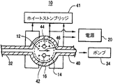
図2は、センサ12、エンクロージャ14及びチャンバ16を含む検出器10の一部の上下横断面図を示す概略図である。触媒感知ビード42及び基準ビード44はエンクロージャ14およびチャンバ16の中に対称に配列されるのが好ましい。ビード42及び44は、エンクロージャ14を通過するガス流れ46に関して対称に配列されている。例えば、ビードはチャンバ16を通過する流路46の軸の両側に互いに等間隔で位置していても良い。ビードは、双方のビードがセンサエンクロージャ14の内部で互いに空間的に位置がずれている一方で、ほぼ同時に同じ流れ条件に実質的にさらされるように流路内で整列されている。ビードは同様の条件の下でガスにさらされるため、ガス流れに対する感知ビードと基準ビードの応答は、感知ビード42でのみ可燃性ガスが燃焼することを除いて同じになるべきである。
FIG. 2 is a schematic diagram showing a vertical cross-sectional view of a part of the
ビード42、44が流路46で互いに関して対称に整列されていることにより、試料ガス流れに可燃性ガスが存在しないときの「オフセット」センサ信号は最小になるはずである。ビードをバランス良く位置決めすれば、チャンバ16を流れるガスの典型的な流量が毎秒数立方センチメートルであるときにオフセットは20ppm未満の可燃性ガスと等価の値まで最小限に抑制されることが実験により判明している。ビードが対称に配列されていないと、オフセットセンサ信号は重大なものになってしまうであろう。そのように大きなオフセットセンサ信号は従来のセンサにおいては一般に見られ、それは、触媒感知ビードと基準ビードが方向及び流量を無作為に変化させようとする流路に配置されているためである。例えば、一方のビードが他方のビードの上流側にある場合、又はビードが実質的にガス試料の同じ流れ条件を受けない場合、ビードのRTDは非対称に応答する。
With the
図3に示すように、検出器10は、ポンプ流路40に配置された「吹き通し」電流制御電解槽50を更に含んでいても良い。電解槽はセンサチャンバ16とポンプ34との間に空気接続されている。電解槽は、ポンプ流路40を流れるガスから周囲水分を吸収することが可能である母材を電流が通過するときに水素ガス(及び酸素)を発生するように設計されている。適切な高速応答電解槽は知られており、ロシア特許第1170277号に示されている。
As shown in FIG. 3, the
センサチャンバ内に至るガス試料の流量は流れ誤差を導入しないようにいつでも相対的に小さいが、通常は数秒という時間の中で0から最大値まで急速な相対変化を示す。センサをゼロ化するために、ガス試料の抽出は5から30秒の期間にわたり中断される。このタイミングは単なる一例として与えられており、本発明はこの周期に限定されない。従って、外部からのガス混合物はセンサチャンバ16内へ絶えずサンプリングされるのではなく、相対的に少量の複数の部分として取り入れられる。それぞれ1回分の試料に含まれる可燃性ガスは、好ましくは試料中の可燃性ガスの完全燃焼が本質的に完了するまで燃焼され(それにより、感知ビードの温度を上昇させ)、その後になって初めてチャンバ16内のガス部分は置き換えられる。第2に、「呼吸」ポンプ34へのガスの流入と、ポンプからのガスの流出は、コイル温度が変化するときにのみ起こることに注意すべきである。ポンプの加熱コイルが一定の温度にとどまっているとき(例えば、絶えず加熱されている間)、「呼吸」は停止しており、チャンバ16を通過するガスの流量は実質的に0のままである。言い換えれば、間欠的で、相対的に短い(たとえば、1秒)「吸い込み」と「吐き出し」がそれより長い(例えば、15秒)休止時間によって分割されているのである。
The flow rate of the gas sample into the sensor chamber is always relatively small so as not to introduce flow errors, but usually shows a rapid relative change from zero to a maximum in a matter of seconds. In order to zero the sensor, the extraction of the gas sample is interrupted for a period of 5 to 30 seconds. This timing is given only as an example, and the present invention is not limited to this period. Accordingly, the gas mixture from the outside is not constantly sampled into the
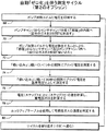
図4から図6は、検出器10を動作させる過程の例を示すプロセスチャートである。図4及び図5は、それぞれが自動ゼロ化(Vr)過程を伴う2つの可燃性物質測定サイクルを示す。図6は、検出器が無力化されているか否かを検査するための校正プロセスを示す。ガス検出器10は、ステップ52、68において「呼吸」ポンプのヒータコイル38を加熱するために、例えば、3Wを供給されても良い。制御装置24はある一定の期間にわたりコイル38に給電しても良い。給電されたとき、ヒータコイルの温度は、例えば、周囲温度より100℃から200℃高い温度まで数秒以内に上昇する。ステップ54で、コイルがポンプチャンバ36の内部のガスを加熱している間、加熱されたガスはポンプ流路40、センサチャンバ16及び流路32を経てボリューム30内まで押し出されて、検出器10をパージングする。このパージ期間中及び特にパージ期間の後(ガス流量がしばらくの間、実質的に0にとどまっているとき)、ステップ56で、ポンプ及び/又は流路40に存在すると思われる可燃性ガスはセンサチャンバ16に流入し、センサ触媒ビード42及び/又はヒータ38において燃え尽きるであろう。基準電圧測定プロセスはガス試料を抽出する直前(図4を参照)又は試料抽出の後(図5を参照)に実行されれば良い。
4 to 6 are process charts illustrating an example of a process of operating the
センサチャンバにおいてパージング過程の間に可燃性ガスの燃焼完了を促進するための技法は、ステップ56でポンプチャンバ内のガスを燃焼させることである。例えば、触媒による燃焼を促進するために、ヒータコイル38にPtの薄い層を塗布しても良い。コイル38が加熱されると、ポンプチャンバ36内の可燃性ガスは、ポンプ流路40を通過してセンサチャンバ16に流入できるようになる前にほぼ燃え尽きてしまう。
A technique for promoting the completion of combustible gas combustion during the purging process in the sensor chamber is to burn the gas in the pump chamber at
チャンバ16内へのガスの流れが遮断され、ステップ56でセンサ12がセンサチャンバ16内に既に存在する可燃性ガスを完全に燃焼させた後、ステップ58において、ホイートストンブリッジの出力が測定される。測定値は後の使用に備えて基準電圧Vrとして制御装置のメモリにデジタル格納される。「基準電圧」(Vr)は、チャンバ16内へのガスの流入が遮断され、チャンバ内の可燃性物質がほぼ完全に燃え尽きた後の「可燃性物質0状態」のブリッジ電圧出力として定義されても良い。あるいは、基準電圧はガスが最初に試料になった後に測定されても良い。この場合に基準電圧Vrを正確に測定するのに適する条件は、ステップ76で、ガス試料の流れが遮断された後(「吸い込み」の終了)に約30秒以上の時間間隔で実現される。
After the flow of gas into the
制御装置24はヒータ38をオフし、薄膜ヒータコイル38を冷却させるが、この冷却には、通常、約1から3秒を要する。ヒータ38及びポンプチャンバ内のガスが冷却されている間、ステップ60、72でポンプは部屋30から所定量の試料ガスを吸い込む。ポンプは部屋ボリューム30から既知の一定量(通常は少量)のガスの試料を拡散制限流路32を介してセンサチャンバ16の中へ吸い込む。
The
ステップ62、74で、吸い込まれたガス試料の中の可燃性ガスは触媒感知ビード42において燃焼される。オプションとして、可燃性物質がほぼ完全に燃え尽きるまで(通常は約30秒間)、ガス試料はチャンバ16の内部にとどまっていても良い。この時点で、ステップ76においてセンサ出力は基準電圧Vrとして測定される。
In
ポンプの「吸い込み」中、ガス試料は制御された量でセンサチャンバ内へ急速に引き込まれる。ガス試料中の可燃性物質が燃焼している間、感知ビード42の温度は一時的に上昇し、ビード抵抗に変化を生じさせる。感知ビードの温度の上昇の結果、ホイートストンブリッジは感知ビード温度を示すブリッジ出力電圧Vmを発生する。ブリッジ出力電圧は、ステップ62で、1回以上のガス試料測定時間に測定される。
During the "priming" of the pump, the gas sample is rapidly drawn into the sensor chamber in a controlled amount. While the combustibles in the gas sample are burning, the temperature of the
ステップ64、78で、ガス試料がポンプにより「吸い込まれた」後、制御装置は1回以上の試料測定時間のVrとVmの差を判定することにより試料ガスにおける可燃性ガス濃度を検出する。このように電圧の差を連続して測定することにより、制御装置は、ステップ66、80において、メモリに格納されたルックアップテーブルを使用して試料ガス中の可燃性ガス濃度の正確且つ精密な読み取り値を生成することができる。ルックアップテーブルは差電圧測定値を試料ガスの燃焼温度に変換する。
In
周囲背景ガスの変化はセンサを頻繁にゼロ化することにより補償され、可燃性ガス濃度の差センサ測定値に影響を及ぼさない。 Changes in the ambient background gas are compensated for by frequent zeroing of the sensor and do not affect the flammable gas concentration difference sensor readings.
触媒センサビードの温度は上昇し、その後、可燃性ガスを含む「吸い込まれた」試料が燃焼するにつれて、試料がチャンバ16内でほぼ完全に燃え尽きるまで温度は下がる。検出器10の一実施例について実施された実験に基づけば、ブリッジ出力の動的特性は可燃性ガスの種類及び/又は試料中に同時に存在する2種類以上の可燃性ガスの濃度の比によって決まる。例えば、最大燃焼速度及びその後の最大ブリッジ出力電圧は、可燃性物質として水素のみを含むガス試料の「吸い込み」後、約5秒で実現され、COのみを含む試料の場合には約9秒で実現される。このデータは2秒未満のガス試料「吸い込み」時間に基づいている。H2/COガス混合物の場合、最大燃焼速度(最大ブリッジ出力電圧により示される)は5から9秒の間隔の間に徐々に変化し、それに伴って混合物中のCO濃度はH2に対して相対的に増加する。チャンバ16内へ新たなガス試料が急速に導入されるために起こるセンサ12の温度上昇の速度は、可燃性ガス混合物の組成を示す。感知ビードの温度上昇の速度は、例えば、「吸い込み」周期に続くいくつかの時間間隔でホイートストンブリッジ出力を測定することにより判定できる。可燃性ガスが燃焼する速度は、試料中の特定の可燃性ガスの拡散係数と、触媒温度によって決まる。そうでなければ、感知ビード42の温度上昇の振幅は低いセンサ検出限界から可燃性ガス濃度の数パーセントの範囲で可燃性ガスの濃度に比例する。
The temperature of the catalytic sensor bead increases, and then decreases as the "inhaled" sample containing flammable gas burns, until the sample is almost completely burned out in
一般に、可燃性ガスの組成の相違による感知ビードの加熱の振幅および速度の変化は、制御装置24に可燃性ガスの種類及び濃度を識別させるか、又は部屋ボリューム30からセンサエンクロージャ16内へ引き込まれるガス試料中の2つの可燃性ガスの比を評価させることにより解析できる。
In general, changes in the amplitude and rate of heating of the sensing bead due to differences in the composition of the flammable gas will cause the
H2濃度とCO濃度の比、並びにそれらのガスの混合物の濃度を実質的に十分な正確さで判定するために簡易アルゴリズムを使用しても良いであろうということが実験により判明している。この目的のために、ガス試料「吸い込み」に続いて、3つの異なる時間間隔で3つのホイートストンブリッジ出力V5、V12及びVrがそれぞれ測定される。「吸い込み」開始(吸い込みの持続時間は約1秒である)から電圧測定までの時間間隔(遅延)は、V5、V12及びVrについて、それぞれ5秒、12秒、30秒である。差V12−VrはCOとH2の濃度の和を表す(それらのガスの試料ガスにおける比とは無関係である)ことがわかっており、これを使用して、制御装置24にルックアップテーブルを使用させることによりCO及びH2という可燃性物質の濃度を判定することができる。比(V5−Vr)/(V12−Vr)は一般に0.9から1.7の範囲にあり、実際にはCO/H2比に対して直線的な関係にあって、0.9の比は100%COに相当し、1.7の比は100%H2に相当する。タイミング及び/又は(V5−Vr)/(V12−Vr)比等価値は特定のセンサの種類及びセンサチャンバの幾何学的特性に特有であっても良い。一般に、予備校正が必要になるであろう。(V5−Vr)/(V12−Vr)を判定することにより、CO及びH2の各々についてガス濃度を判定できる。従って、1回の測定サイクルから、センサビードの同じ温度で、COとH2の個別の濃度レベル及び組み合わせ濃度レベルを判定することができる。差電圧(V5−Vr)及び(V12−Vr)はステップ64で測定される。ステップ66では、制御装置がCO対H2比ルックアップテーブルを比較して使用し、線形近似を実行することにより、COとH2の総濃度(個別及び和)を求めることができるであろう。
The ratio of the concentration of H 2 and CO concentrations, as well as that will be used a simple algorithm to determine the concentration of a mixture of these gases in a substantially sufficient accuracy has been found by experiment . To this end, following a gas sample "suction", three Wheatstone bridge output V 5, V 12 and V r are respectively measured at three different time intervals. "Suction" start (the suction duration is about a is 1 second) time interval from to voltage measurement (delayed), for V 5, V 12 and V r, respectively 5 seconds, 12 seconds, and 30 seconds. It has been found that the difference V 12 -V r represents the sum of the concentrations of CO and H 2 (independent of the ratio of those gases in the sample gas) and is used to look up the
COとH2の濃度を相対的に高い正確さで判定するためには、1分以上の測定サイクルが要求されるであろう。可燃性ガスに関するガス試料の組成がわかっており、可燃性ガスの和が唯一の関心事項である場合には、これより著しく短い測定サイクルが使用されても良い。あるいは、制御装置においてソフトウェアで切り替えを開始しつつ、短い測定サイクルと長い測定サイクルを交互に実行することも可能である。例えば、「長い」測定サイクルを使用することにより、制御装置はある所定のプロセスでCO/H2比を最初に一度測定できる。その後、制御装置は、測定されたCO/H2比が一定の既知の量(最前の長いサイクルで測定された)であると想定する「高速」測定サイクルを自動的に適用しても良い。制御装置は、CO/H2比を再度測定するために、周期的に長いサイクルを実行しても良い。 To determine the CO and the concentration of H 2 at a relatively high accuracy will be measuring cycle at least 1 minute is required. If the composition of the gas sample for the flammable gas is known and the sum of the flammable gases is of sole concern, a significantly shorter measurement cycle may be used. Alternatively, a short measurement cycle and a long measurement cycle can be alternately executed while switching is started by software in the control device. For example, "long" Using a measurement cycle, the controller may first measure once CO / H 2 ratio at a predetermined process in the. Thereafter, the controller may automatically apply the measured CO / H 2 ratio is assumed to be constant known amount (measured at the forefront of long cycle) "fast" measurement cycle. Controller, for measuring the CO / H 2 ratio again, may be performed periodically long cycle.
ガス試料抽出(「吸い込み」)の時間間隔が相対的に短い場合、実際にはセンサ信号全体の交番部分である、測定サイクル中のセンサ出力の最大値と最小値の差を測定することにより、可燃性物質の組み合わせ濃度を判定できる。 If the time interval between gas sampling ("suck") is relatively short, by measuring the difference between the maximum and minimum values of the sensor output during the measurement cycle, which is in fact the alternating part of the total sensor signal, The combination concentration of combustible substances can be determined.
検出器は、ステップ66で、測定サイクル終了ごとに「ゼロ」自動校正を自動的に実行する。自動ゼロ化方法は、検出器が測定サイクル中の感知ビードの温度の変化を約0.002℃まで検出することにより、試料ガスにおける少量の可燃性物質の正確な測定を可能にする。自動ゼロ化は、ステップ76のように「吸い込み」過程の終了時に、又はステップ58のように「吐き出し」過程の終了直前に基準センサ出力(Vr)を測定することにより実行されても良い。
The detector automatically performs a "zero" auto-calibration at
測定サイクルの間、検出器は少量のガス試料、例えば、0.1ccから1ccをセンサチャンバ16内へ「吸い込んで」も良い。チャンバは約2ccの容積を有すると考えられるので、少量のガス試料は(ガス試料より相当に大きいチャンバ容積を有するチャンバに入るときに)希釈される。発明者の実験においては、検出器は空気中の「外部」H2濃度を8%(2LEL)まで高い信頼性で測定した。
During the measurement cycle, the detector may “suck” a small sample of gas, eg, 0.1 cc to 1 cc, into the
感度の自動校正は周期的に、たとえば、数分ごとから数時間に1回のペースで実行されても良い。周囲水分型電解槽が使用される場合、試料ガスから戻される電解水を補給することにより、再校正サイクル時間は制限される。通常、1回の校正に必要とされる5mm3から10mm3のH2は、30℃露点(霜点)(DP)条件の下であっても約20分で周囲水分により補給されるのが理想的である。DPが高くなるほど、周囲水分による補給は速くなる。現実には、特にDPの低いガス試料に対しては、補給に1時間を超える時間が要求されるであろう。煙道ガスのDP温度は通常は+50℃に近いため、水分制限は煙道ガス解析に関しては問題ではない。空気中に、LELよりかなり低い濃度であっても水素又は炭化水素が存在する場合、センサにおける燃焼によって著しく大量の水分が発生されるであろうということに注意すべきである。 Automatic calibration of the sensitivity may be performed periodically, for example, every few minutes to once every several hours. If an ambient moisture cell is used, the recalibration cycle time is limited by replenishing the electrolytic water returned from the sample gas. Usually, 5 mm 3 to 10 mm 3 of H 2 required for one calibration is replenished with ambient moisture in about 20 minutes even under 30 ° C. dew point (frost point) (DP) conditions. Ideal. The higher the DP, the faster the supply with ambient moisture. In practice, especially for low DP gas samples, more than an hour will be required for replenishment. Moisture restriction is not an issue for flue gas analysis because the flue gas DP temperature is typically close to + 50 ° C. It should be noted that if hydrogen or hydrocarbons are present in the air, even at concentrations significantly lower than LEL, combustion at the sensor will generate a significant amount of moisture.
図6に示すように、感度校正は、ステップ82に示すとおり、残留するガス部分をポンプでチャンバ16を介して、更に外部の部屋まで排出する定期(第1回)ポンプ「吐き出し」から始まる。センサ出力(V0)は「吐き出し」開始から所定の時間遅延を経て測定される(ステップ84)。定期「吸い込み」(ステップ86)の後、次の(第2回)「吐き出し」過程の開始前に、ステップ88で、電解槽50のエンクロージャ51の内部に一定量の水素を発生するために電解槽50に所定の量の電気が通される。この目的のために、電解槽には、例えば、1mAから10mAの範囲の一定の電流が一定の期間、例えば、1秒から10秒にわたり供給される。この水素発生周期は、定期試料ガス測定中のポンプ「吐き出し」過程と「吸い込み」過程の間の周期より短いのが好ましい。発生される、例えば、0.1mm3から10mm3程度の相対的に少量の水素は、通常、校正には十分である。
As shown in FIG. 6, the sensitivity calibration starts with a periodic (first) pump “discharge” in which a residual gas portion is pumped out through the
ステップ90で、ポンプは2回目の「吐き出し」を実行する。この2回目の「吐き出し」の間にポンプから電解槽のチャンバ51を介してチャンバ16へ搬送されるガス部分は、電解槽で発生された一定量の水素を含む。ステップ92では、水素の燃焼中に、2回目の「吐き出し」から好ましくは1回目の「吐き出し」の開始の後のV0と同じ時間遅延を伴って、センサ出力(Vc)が測定される。この時間遅延は、通常、2秒から10秒であるが、最適の値はセンサチャンバへ試料として導入される水素の最大燃焼速度の時間に相当し、通常は6秒に近い。「吐き出される」ガスの量が制御されており(一定であり)、また、発生される水素の量が繰り返し可能であるため、更に長い期間、たとえば、数年間にわたり、十分に高い正確さ及び繰り返し精度をもって校正プロセスを、例えば、数時間ごとに繰り返すことができる。電解水は周囲環境から補給されるので、電解槽は何年にもわたり手作業による点検を必要としないであろう。
In
ステップ94では、VcとV0の差が制御装置24により評価され、メモリに格納されている、この差の許容範囲と比較される。センサの感度が十分であれば、VcとV0の差は所定の範囲内にある。ステップ94では、Vc−V0比較に基づいて、センサの感度及びセンサ調整に関する決定又は自動アクションが実行される。V0及びVcはVrに関する差信号として測定されるか、あるいは絶対値として測定されれば良い。いずれにせよ、V0をVcから減算する間にVrは相殺される。
In
図6に示すゼロ感知方法の場合、校正サイクルが終了するたびに自動校正によりセンサの無力化を迅速に検出できる。測定サイクルの「吐き出し」段階の間に感度校正が実行されるため、校正は実質的に検出器ユーザに対して透明であり、定期LEL測定を妨害又は中断しない。水素と並行して発生される相対的に少量の酸素は、ガス試料中に通常はそれより著しく多い量のO2が既に存在しているために、センサ校正の正確さに影響を及ぼさない。 In the case of the zero sensing method shown in FIG. 6, each time the calibration cycle is completed, the neutralization of the sensor can be quickly detected by automatic calibration. Because the sensitivity calibration is performed during the "exhale" phase of the measurement cycle, the calibration is substantially transparent to the detector user and does not disturb or interrupt periodic LEL measurements. Relatively small amount of oxygen generated in parallel with hydrogen to O 2 in an amount usually significantly higher than in the gas sample is already present, it does not affect the accuracy of the sensor calibration.
ここで開示した検出器10は、長期間安定性を改善し、校正に要求される条件を最小限に抑えるために各々の測定から次の測定までの間に透明自動「ゼロ化」を実行すること;センサ無力化成分を含む可能性があるガス試料に感知ビードがさらされるのを抑制すること;煙道ガス解析に特に適用できると考えられるCOとH2の濃度の別個の測定を実行すること;±10ppm(百万分率)までの検出感度レベルで可燃性ガスの濃度を測定すること;ガスタービンエンクロージャの内部などの周囲ガス流量が大きい適用用途において可燃性物質を測定すること;センサを試料抽出ポイントから数メートルまでの遠隔場所に配置できること;センサがオンラインである間にセンサ感度を自動的に監視し、調整すること;後の測定に備えて急速にセンサを回復しつつ、LELレベルを著しく超えるレベルの可燃性物質の濃度を高い信頼性で測定することなどの特徴及び機能を含んでいても良い。
The disclosed
ここで説明するようなゼロ校正及び感度校正は、センサにおける補助的で、相対的に稀な(例えば、数時間に1回)手続きとして共に採用されても良く、そのような校正がなければLEL検出器の高速応答条件を満たすためにガス試料抽出は中断され、周知の標準ブリッジ出力測定が実行されることになる。 Zero calibration and sensitivity calibration as described herein may be employed together as ancillary, relatively rare (eg, once every few hours) procedures in sensors, and without such calibration LEL Gas sampling is interrupted to meet the fast response requirements of the detector and a well-known standard bridge power measurement will be performed.
本発明を現時点で最も実用的で好ましい実施例であると考えられるものに関連して説明したが、本発明は開示された実施例に限定されるべきではなく、また、特許請求の範囲に記載された符号は、理解容易のためであってなんら発明の技術的範囲を実施例に限縮するものではない。 Although the present invention has been described in connection with what is presently considered to be the most practical and preferred embodiment, the present invention should not be limited to the disclosed embodiments, but rather should be described in the following claims. The reference numerals given are for easy understanding and do not limit the technical scope of the invention to the embodiments.
10…可燃性ガス検出器、12…可燃性ガスセンサ、14…保護エンクロージャ、16…流通チャンバ、24…制御装置、30…周囲ガスボリューム、32…拡散制限流路、34…試料抽出用ポンプ、36…密閉ポンプチャンバ、38…ヒータコイル、40…排出流路、41…ホイートストンブリッジ、42…触媒感知ビード、44…基準ビード
DESCRIPTION OF
Claims (10)
周囲ガスのボリュームからの触媒センサへのガス拡散を最小限に抑えるために前記触媒センサを流通チャンバ(16)内に収納することと、
前記周囲ガスのボリュームから周囲ガスの個別のガス試料を前記流通チャンバへ引き込むこと(60、72)と、
前記ガス試料が前記流通チャンバに流入した後、前記流通チャンバ内への周囲ガスの流れを遮断することと、
前記ガス流れの遮断と同時に前記触媒センサの出力を測定すること(62、76)とから成る方法。 In a method for measuring a flammable gas using a catalyst sensor (12),
Housing said catalyst sensor in a flow chamber (16) to minimize gas diffusion from the volume of ambient gas to the catalyst sensor;
Drawing (60, 72) an individual gas sample of ambient gas from the volume of ambient gas into the flow chamber;
After the gas sample flows into the flow chamber, shutting off the flow of ambient gas into the flow chamber;
Measuring the output of said catalyst sensor simultaneously with said shutting off said gas flow (62, 76).
前記流通チャンバから周囲ガスを吐き出すこと(54)と、
前記流通チャンバ内に残留する可燃性ガスを燃焼させること(56)と、
前記流通チャンバ内に残留する可燃性ガスを燃焼させた後、前記触媒センサからの基準出力信号を測定すること(62)とを更に含む請求項1記載の方法。 Before drawing a gas stream into the flow chamber, the method comprises:
Exhaling ambient gas from the flow chamber (54);
Combusting the combustible gas remaining in the flow chamber (56);
The method of claim 1, further comprising measuring a reference output signal from the catalyst sensor after burning the combustible gas remaining in the flow chamber.
パージングガスに所定の量の水素を導入し(88)、その後、前記触媒センサの流通チャンバを2度目にパージングし(90)、
2度目のパージングの後に前記触媒センサの第2の出力を測定し(92)、
第1の出力と第2の出力の差に基づいてセンサ感度を判定する(94)ことにより、センサ感度を判定することを更に含む請求項1記載の方法。 Purging the flow chamber of the catalyst sensor (82), and then measuring a first output of the catalyst sensor (84);
A predetermined amount of hydrogen is introduced into the purging gas (88), and then the flow chamber of the catalyst sensor is purged a second time (90),
After the second purging, the second output of the catalyst sensor is measured (92),
The method of claim 1, further comprising determining sensor sensitivity by determining (94) sensor sensitivity based on a difference between the first output and the second output.
周囲ガスを透過せず、第1のガス拡散制限流路(32)に結合されたポートと、第2の拡散制限流路(40)に結合された第2のポートとを有するチャンバ(16)と、
前記チャンバ内に配置された可燃性ガスの触媒センサ(12)とを具備し、
前記第1のガス拡散制限流路(32)は周囲ガスのボリューム(30)に接続可能であり、
前記第2の拡散制限流路(40)を介して前記チャンバに空気接続されたガスポンプ(34)を更に具備する検出器。 In a detector (10) for detecting a combustible substance in an ambient gas,
A chamber impermeable to ambient gas and having a port coupled to the first gas diffusion-restricted flow path and a second port coupled to the second gas diffusion-restricted flow path; When,
A combustible gas catalyst sensor (12) disposed in the chamber;
Said first gas diffusion limiting channel (32) is connectable to a volume (30) of ambient gas;
A detector further comprising a gas pump (34) pneumatically connected to the chamber via the second diffusion limited flow path (40).
Applications Claiming Priority (1)
| Application Number | Priority Date | Filing Date | Title |
|---|---|---|---|
| US10/442,070 US7062952B2 (en) | 2003-05-21 | 2003-05-21 | Combustible gas detector having flow-through sensor container and method for measuring such gases |
Publications (3)
| Publication Number | Publication Date |
|---|---|
| JP2004347601A true JP2004347601A (en) | 2004-12-09 |
| JP2004347601A5 JP2004347601A5 (en) | 2007-07-05 |
| JP4671623B2 JP4671623B2 (en) | 2011-04-20 |
Family
ID=33097978
Family Applications (1)
| Application Number | Title | Priority Date | Filing Date |
|---|---|---|---|
| JP2004149866A Expired - Fee Related JP4671623B2 (en) | 2003-05-21 | 2004-05-20 | Combustible gas detector with flow sensor container and method for measuring combustible gas |
Country Status (3)
| Country | Link |
|---|---|
| US (1) | US7062952B2 (en) |
| EP (1) | EP1480035A3 (en) |
| JP (1) | JP4671623B2 (en) |
Cited By (4)
| Publication number | Priority date | Publication date | Assignee | Title |
|---|---|---|---|---|
| JP2006177863A (en) * | 2004-12-24 | 2006-07-06 | Riken Keiki Co Ltd | Calibration method and gas detection device with calibration function |
| JP2007518076A (en) * | 2004-01-06 | 2007-07-05 | ゼネラル・エレクトリック・カンパニイ | Gas supply pump to sensor and method thereof |
| JP2018040614A (en) * | 2016-09-06 | 2018-03-15 | 理研計器株式会社 | Gas sensor unit and gas detection device |
| JP2023159874A (en) * | 2022-04-20 | 2023-11-01 | ドレーガー セイフティー アクチエンゲゼルシャフト ウント コンパニー コマンディートゲゼルシャフト アウフ アクチエン | Gas detection device and gas detection method equipped with sensor parts and oxidation parts |
Families Citing this family (15)
| Publication number | Priority date | Publication date | Assignee | Title |
|---|---|---|---|---|
| CA2548767A1 (en) * | 2003-12-03 | 2005-06-23 | Proton Energy Systems, Inc. | System for generating hydrogen and method thereof |
| US20060191318A1 (en) * | 2005-02-25 | 2006-08-31 | Mcbride Charles L | Digitally accessible sensor |
| DE102005012250A1 (en) * | 2005-03-15 | 2006-09-21 | Bosch Rexroth Aktiengesellschaft | Device for the protection of electric motors |
| GB0525517D0 (en) * | 2005-12-15 | 2006-01-25 | Boc Group Plc | Apparatus for detecting a flammable atmosphere |
| JP4199254B2 (en) * | 2006-04-19 | 2008-12-17 | リンナイ株式会社 | Combustion device |
| CN101021542B (en) * | 2007-02-21 | 2013-10-30 | 中国矿业大学 | Minepit environment flammable gas analyzing method and device |
| GB2446824B (en) * | 2007-02-26 | 2009-06-17 | Thermo Fisher Scientific Inc | Apparatus and method for detecting incomplete combustion in a combustion analyser |
| DE102008024769B4 (en) | 2008-05-23 | 2014-01-30 | Eads Deutschland Gmbh | Apparatus and method for detecting trace gases |
| US9110041B2 (en) | 2011-08-04 | 2015-08-18 | Aramco Services Company | Self-testing combustible gas and hydrogen sulfide detection apparatus |
| EP2775464B1 (en) * | 2013-03-06 | 2018-01-17 | Siemens Schweiz AG | Hazard alarm comprising a contactless thermal radiation sensor for determining an ambient temperature |
| US10578573B2 (en) * | 2013-03-12 | 2020-03-03 | Msa Technology, Llc | Diagnostics for catalytic structures and combustible gas sensors including catalytic structures |
| CN109142006B (en) * | 2018-11-09 | 2023-09-05 | 交通运输部天津水运工程科学研究所 | Device and method for precise positioning and rapid embedding of micro sensors |
| CN111366609A (en) * | 2020-03-15 | 2020-07-03 | 莱浦顿(上海)工程技术有限公司 | Combustible gas analyzer |
| CN112730525B (en) * | 2020-12-25 | 2024-01-16 | 杭州绿洁科技股份有限公司 | Low-concentration trace water sample pH conductivity detector |
| CN117074114B (en) * | 2023-08-11 | 2025-09-12 | 中国科学技术大学 | Gas sampling device and online monitoring and identification equipment for battery thermal runaway gas |
Citations (6)
| Publication number | Priority date | Publication date | Assignee | Title |
|---|---|---|---|---|
| US2663379A (en) * | 1948-05-10 | 1953-12-22 | Phillips Petroleum Co | Apparatus for hydrocarbon determination |
| JPS55146024A (en) * | 1979-02-26 | 1980-11-14 | Draegerwerk Ag | Gas measuring device |
| JPH01202675A (en) * | 1988-02-09 | 1989-08-15 | Fuji Electric Co Ltd | Apparatus for detecting combustible gas in oil |
| JPH0221543U (en) * | 1988-07-29 | 1990-02-13 | ||
| JPH063311A (en) * | 1992-06-22 | 1994-01-11 | Snow Brand Milk Prod Co Ltd | Method for measuring heat conductivity of fluid and instrument from measuring state of fluid |
| JP2001041916A (en) * | 1999-05-21 | 2001-02-16 | Daikin Ind Ltd | Gas detector |
Family Cites Families (12)
| Publication number | Priority date | Publication date | Assignee | Title |
|---|---|---|---|---|
| GB520993A (en) | 1938-08-09 | 1940-05-09 | Mine Safety Appliances Co | Improvements in or relating to apparatus for testing gas for combustible constituents |
| US2349250A (en) * | 1939-10-09 | 1944-05-23 | Phillips Petroleum Co | Gas detection |
| DE1498784C3 (en) | 1964-01-21 | 1973-10-11 | Rolf H. Dipl.-Ing. 4600 Dortmund Huebner | Portable measuring device for determining the concentration of various gases in the weather stream for a few days |
| US3687631A (en) | 1969-06-03 | 1972-08-29 | Scott Research Lab Inc | Method and equipment for catalytic analysis of gases |
| US4115229A (en) | 1976-11-08 | 1978-09-19 | Thermo-Lab Instruments, Inc. | Apparatus for sampling a gaseous stream |
| US4169769A (en) | 1976-11-08 | 1979-10-02 | Thermo-Lab Instruments, Inc. | Method for conveying a gas sample through an analyzer chamber |
| SU1170277A1 (en) | 1984-02-27 | 1985-07-30 | Предприятие П/Я Р-6900 | Electrochemical gas metering device |
| GB2329716B (en) | 1994-09-30 | 1999-05-12 | Mine Safety Appliances Co | Method of determining concentration of combustible gas |
| US5748492A (en) * | 1995-05-24 | 1998-05-05 | Badger Meter, Inc. | Measuring heating value using catalytic combustion |
| RU2156972C1 (en) | 1999-09-09 | 2000-09-27 | Савельев Владимир Алексеевич | Method determining concentration of combustible gases in oxygen-carrying atmosphere |
| RU2142624C1 (en) | 1999-02-26 | 1999-12-10 | Савельев Владимир Алексеевич | Method determining concentration of combustible gases in oxygen-carrying atmosphere |
| WO2003008928A2 (en) | 2001-07-16 | 2003-01-30 | Sensor Tech, Inc. | Sensor device and method for qualitative and quantitative analysis of gas phase substances |
-
2003
- 2003-05-21 US US10/442,070 patent/US7062952B2/en not_active Expired - Lifetime
-
2004
- 2004-05-20 JP JP2004149866A patent/JP4671623B2/en not_active Expired - Fee Related
- 2004-05-21 EP EP04253027A patent/EP1480035A3/en not_active Withdrawn
Patent Citations (6)
| Publication number | Priority date | Publication date | Assignee | Title |
|---|---|---|---|---|
| US2663379A (en) * | 1948-05-10 | 1953-12-22 | Phillips Petroleum Co | Apparatus for hydrocarbon determination |
| JPS55146024A (en) * | 1979-02-26 | 1980-11-14 | Draegerwerk Ag | Gas measuring device |
| JPH01202675A (en) * | 1988-02-09 | 1989-08-15 | Fuji Electric Co Ltd | Apparatus for detecting combustible gas in oil |
| JPH0221543U (en) * | 1988-07-29 | 1990-02-13 | ||
| JPH063311A (en) * | 1992-06-22 | 1994-01-11 | Snow Brand Milk Prod Co Ltd | Method for measuring heat conductivity of fluid and instrument from measuring state of fluid |
| JP2001041916A (en) * | 1999-05-21 | 2001-02-16 | Daikin Ind Ltd | Gas detector |
Cited By (5)
| Publication number | Priority date | Publication date | Assignee | Title |
|---|---|---|---|---|
| JP2007518076A (en) * | 2004-01-06 | 2007-07-05 | ゼネラル・エレクトリック・カンパニイ | Gas supply pump to sensor and method thereof |
| JP2006177863A (en) * | 2004-12-24 | 2006-07-06 | Riken Keiki Co Ltd | Calibration method and gas detection device with calibration function |
| JP2018040614A (en) * | 2016-09-06 | 2018-03-15 | 理研計器株式会社 | Gas sensor unit and gas detection device |
| JP2023159874A (en) * | 2022-04-20 | 2023-11-01 | ドレーガー セイフティー アクチエンゲゼルシャフト ウント コンパニー コマンディートゲゼルシャフト アウフ アクチエン | Gas detection device and gas detection method equipped with sensor parts and oxidation parts |
| JP7689154B2 (en) | 2022-04-20 | 2025-06-05 | ドレーガー セイフティー アクチエンゲゼルシャフト ウント コンパニー コマンディートゲゼルシャフト アウフ アクチエン | Gas detector including sensor component and oxidation component, and gas detection method |
Also Published As
| Publication number | Publication date |
|---|---|
| US7062952B2 (en) | 2006-06-20 |
| JP4671623B2 (en) | 2011-04-20 |
| US20040231399A1 (en) | 2004-11-25 |
| EP1480035A2 (en) | 2004-11-24 |
| EP1480035A3 (en) | 2004-12-15 |
Similar Documents
| Publication | Publication Date | Title |
|---|---|---|
| JP4671623B2 (en) | Combustible gas detector with flow sensor container and method for measuring combustible gas | |
| JP6023075B2 (en) | Method and apparatus for measuring respiratory alcohol concentration | |
| WO2010025601A1 (en) | Self-calibrating gas sensor | |
| ES2686623T3 (en) | Discrimination device and procedure of a sample gas | |
| CN112534252B (en) | Flame ionization detector and method for analyzing oxygen-containing measuring gas | |
| US20110048108A1 (en) | Gas sensor | |
| JP2007501946A (en) | Leakage detection apparatus and method using accumulation method | |
| US7704748B2 (en) | Gas analyzer for measuring the flammability of mixtures of combustible gases and oxygen | |
| EP2581738B1 (en) | Calibration technique for calibrating a zirconium oxide oxygen sensor and calibrated sensor | |
| KR200453056Y1 (en) | Volatile Organic Compound Detector | |
| JPH03282247A (en) | Detection of flammable gas | |
| US7056098B2 (en) | Pump for supplying a gas to a sensor and methods therefor | |
| JP2025108578A (en) | Gas detector including sensor component and oxidation component, and gas detection method | |
| US20050251060A1 (en) | Methods of detecting gaseous component levels in a breath | |
| USRE29209E (en) | Method and apparatus for continuously sensing the condition of a gas stream | |
| JPS61274259A (en) | Analyzer for trace of carbon in sample | |
| KR102330982B1 (en) | Breath alcohol analyzer with exhalation temperature measurement function | |
| JPH1019865A (en) | Breath analyzer | |
| JP6004535B2 (en) | Gas detector | |
| US20060175208A1 (en) | Water-conductivity CO2 sensor | |
| JP2020106278A (en) | Combustion type carbon analysis device and carbon analysis method | |
| KR101179783B1 (en) | Explosion proof system of temperature chamber integrated with nitrogen purge equipment and explosion proof method of using the same | |
| JP4497658B2 (en) | Gas detection method and apparatus | |
| JP2004340328A (en) | Air purge device | |
| WO2026033251A1 (en) | Gas sensing system |
Legal Events
| Date | Code | Title | Description |
|---|---|---|---|
| A521 | Written amendment |
Free format text: JAPANESE INTERMEDIATE CODE: A523 Effective date: 20070515 |
|
| A621 | Written request for application examination |
Free format text: JAPANESE INTERMEDIATE CODE: A621 Effective date: 20070515 |
|
| A977 | Report on retrieval |
Free format text: JAPANESE INTERMEDIATE CODE: A971007 Effective date: 20081201 |
|
| A131 | Notification of reasons for refusal |
Free format text: JAPANESE INTERMEDIATE CODE: A131 Effective date: 20090630 |
|
| A601 | Written request for extension of time |
Free format text: JAPANESE INTERMEDIATE CODE: A601 Effective date: 20090930 |
|
| A602 | Written permission of extension of time |
Free format text: JAPANESE INTERMEDIATE CODE: A602 Effective date: 20091005 |
|
| A521 | Written amendment |
Free format text: JAPANESE INTERMEDIATE CODE: A523 Effective date: 20100104 |
|
| RD02 | Notification of acceptance of power of attorney |
Free format text: JAPANESE INTERMEDIATE CODE: A7422 Effective date: 20100104 |
|
| RD04 | Notification of resignation of power of attorney |
Free format text: JAPANESE INTERMEDIATE CODE: A7424 Effective date: 20100105 |
|
| A131 | Notification of reasons for refusal |
Free format text: JAPANESE INTERMEDIATE CODE: A131 Effective date: 20100202 |
|
| A601 | Written request for extension of time |
Free format text: JAPANESE INTERMEDIATE CODE: A601 Effective date: 20100430 |
|
| A602 | Written permission of extension of time |
Free format text: JAPANESE INTERMEDIATE CODE: A602 Effective date: 20100510 |
|
| A521 | Written amendment |
Free format text: JAPANESE INTERMEDIATE CODE: A523 Effective date: 20100514 |
|
| A131 | Notification of reasons for refusal |
Free format text: JAPANESE INTERMEDIATE CODE: A131 Effective date: 20100601 |
|
| A601 | Written request for extension of time |
Free format text: JAPANESE INTERMEDIATE CODE: A601 Effective date: 20100901 |
|
| A602 | Written permission of extension of time |
Free format text: JAPANESE INTERMEDIATE CODE: A602 Effective date: 20100906 |
|
| A521 | Written amendment |
Free format text: JAPANESE INTERMEDIATE CODE: A523 Effective date: 20101129 |
|
| TRDD | Decision of grant or rejection written | ||
| A01 | Written decision to grant a patent or to grant a registration (utility model) |
Free format text: JAPANESE INTERMEDIATE CODE: A01 Effective date: 20101221 |
|
| A01 | Written decision to grant a patent or to grant a registration (utility model) |
Free format text: JAPANESE INTERMEDIATE CODE: A01 |
|
| A61 | First payment of annual fees (during grant procedure) |
Free format text: JAPANESE INTERMEDIATE CODE: A61 Effective date: 20110118 |
|
| R150 | Certificate of patent or registration of utility model |
Free format text: JAPANESE INTERMEDIATE CODE: R150 |
|
| FPAY | Renewal fee payment (event date is renewal date of database) |
Free format text: PAYMENT UNTIL: 20140128 Year of fee payment: 3 |
|
| R250 | Receipt of annual fees |
Free format text: JAPANESE INTERMEDIATE CODE: R250 |
|
| R250 | Receipt of annual fees |
Free format text: JAPANESE INTERMEDIATE CODE: R250 |
|
| R250 | Receipt of annual fees |
Free format text: JAPANESE INTERMEDIATE CODE: R250 |
|
| LAPS | Cancellation because of no payment of annual fees |