JP2004355152A - Interphone master unit and security system - Google Patents
Interphone master unit and security system Download PDFInfo
- Publication number
- JP2004355152A JP2004355152A JP2003149857A JP2003149857A JP2004355152A JP 2004355152 A JP2004355152 A JP 2004355152A JP 2003149857 A JP2003149857 A JP 2003149857A JP 2003149857 A JP2003149857 A JP 2003149857A JP 2004355152 A JP2004355152 A JP 2004355152A
- Authority
- JP
- Japan
- Prior art keywords
- unit
- electric lock
- signal
- locking
- security
- Prior art date
- Legal status (The legal status is an assumption and is not a legal conclusion. Google has not performed a legal analysis and makes no representation as to the accuracy of the status listed.)
- Granted
Links
- 230000005856 abnormality Effects 0.000 claims abstract description 21
- 238000001514 detection method Methods 0.000 claims description 19
- 230000002265 prevention Effects 0.000 claims description 7
- 238000012795 verification Methods 0.000 claims description 5
- 238000013500 data storage Methods 0.000 description 12
- 230000005236 sound signal Effects 0.000 description 12
- 238000010586 diagram Methods 0.000 description 10
- 230000005540 biological transmission Effects 0.000 description 9
- 230000007246 mechanism Effects 0.000 description 9
- 230000008054 signal transmission Effects 0.000 description 9
- 238000003384 imaging method Methods 0.000 description 8
- 238000000034 method Methods 0.000 description 8
- 230000008569 process Effects 0.000 description 8
- 230000033228 biological regulation Effects 0.000 description 3
- 230000000694 effects Effects 0.000 description 2
- 230000007274 generation of a signal involved in cell-cell signaling Effects 0.000 description 2
- 230000003287 optical effect Effects 0.000 description 2
- 230000009471 action Effects 0.000 description 1
- 238000006243 chemical reaction Methods 0.000 description 1
- 230000000295 complement effect Effects 0.000 description 1
- 230000006378 damage Effects 0.000 description 1
- 230000005674 electromagnetic induction Effects 0.000 description 1
- 239000005357 flat glass Substances 0.000 description 1
- 239000004973 liquid crystal related substance Substances 0.000 description 1
- 239000011159 matrix material Substances 0.000 description 1
- 229910044991 metal oxide Inorganic materials 0.000 description 1
- 150000004706 metal oxides Chemical class 0.000 description 1
- 238000012986 modification Methods 0.000 description 1
- 230000004048 modification Effects 0.000 description 1
- 238000003825 pressing Methods 0.000 description 1
- 230000004044 response Effects 0.000 description 1
- 239000004065 semiconductor Substances 0.000 description 1
Images


Landscapes
- Interconnected Communication Systems, Intercoms, And Interphones (AREA)
- Lock And Its Accessories (AREA)
- Alarm Systems (AREA)
Abstract
Description
【0001】
【発明の属する技術分野】
本発明は、住宅やビルに構築されるセキュリティシステムの技術分野に属し、特に、電気信号による指令によりドア等の施解錠を自動的に行う電気錠を備えたものに関する。
【0002】
【従来の技術】
住宅やビルに構築されるセキュリティシステムとして、例えば、下記特許文献1に記載されたものがある。
【0003】
この特許文献1には、防犯用の異常検知を行うための防犯センサと、家屋内に設置される制御ユニットと、屋外に設置される防犯表示盤と、電気信号による指令によりドア等の施解錠を自動的に行う電気錠とを備え、防犯表示盤に備えられるカードデータ読取器でIDカードの適正なIDコードを読み取ったときに、防犯センサを警戒モードとその解除モードとの間で切り替えるとともに、警戒モードの設定と同時に電気錠の施錠を行い、警戒モードの解除と同時に電気錠の解錠を行うように構成したセキュリティシステムが記載されている。
【0004】
【特許文献1】
特開平5−321523号公報
【0005】
【発明が解決しようとする課題】
しかしながら、特許文献1にあっては、例えばごみを出しにいくとか、近隣の家に物を渡しに行く等、僅かな時間だけ住戸を離れる際は、念のため玄関ドアを施錠するものの、警戒モードに設定するほどでもないと考える居住者が存在する場合に対応することはできない。
【0006】
一方、警戒モードに設定する入力を行うための操作装置を室内に配設し、この操作装置を操作すると直ちにこの警戒モードに設定されるように構成した場合、居住者が住戸の外に出て施錠するまでに、防犯センサはすでに作動状態となっているから、それまでの居住者の行動によって防犯センサが反応し、異常が発生したものとして例えば警備センターに報知されることとなる。
【0007】
また、警戒モードに設定する入力を行うための操作装置を室内に配設し、この操作装置を操作してから一定時間待機してから警戒モードに設定するように構成した場合には、前述のような誤報知が低減されるが、その待機動作が終了するまでに居住者による施錠動作が完了すると、居住者は、警戒モードに設定されたか否かを確認するためには待機しなければならない。
【0008】
本発明は、このような事情に鑑みてなされたものであり、上記のような待機時間の発生や誤報知を防止し、且つ居住者が必要と考えるときにのみ防犯用の異常検知を行うモードに設定することのできるセキュリティシステムを提供することを目的とする。
【0009】
【課題を解決するための手段】
請求項1に記載の発明は、扉の施錠と解錠とを行う電気錠と通信可能に接続され、防犯用の異常検出を行う1または複数の異常検出センサに該異常検出を行わせるセキュリティモードの設定と、該セキュリティモードの解除とを行うモード設定部と、前記モード設定部に前記セキュリティモードの設定を待機させる指示を入力するための操作部と、前記電気錠に対する施錠操作または解錠操作が行われると、前記電気錠の動作を制御する施解錠制御部とを備え、前記モード設定部は、前記操作部が操作されると、前記電気錠による施錠動作が行われるまで前記セキュリティモードの設定動作を待機し、前記電気錠による施錠動作が行われると前記セキュリティモードに設定することを特徴とするインターホン親機である。
【0010】
この発明によれば、モード設定部は、操作部が操作されると、電気錠による施錠動作が行われるまでセキュリティモードの設定動作を待機し、電気錠による施錠動作が行われるとセキュリティモードに設定するようにしたので、従来のような待機時間の発生や誤報知を防止し、且つ居住者が必要と考えて操作部が操作されたときにのみ防犯用の異常検知を行うモードに設定することができる。
【0011】
請求項2に記載の発明は、請求項1に記載のインターホン親機において、前記モード設定部は、前記電気錠による解錠動作が行われると、前記セキュリティモードを解除することを特徴とするものである。
【0012】
この発明によれば、電気錠による解錠動作が行われると、セキュリティモードを解除するようにしたので、電気錠の解錠とセキュリティモードの解除とが異なる操作で実行される構成に比して、操作の手間を省くことができる。
【0013】
請求項3に記載の発明は、請求項1または2に記載のインターホン親機において、前記モード設定部により前記セキュリティモードが設定及び/または解除されると、その旨を報知する報知部を備えることを特徴とするものである。
【0014】
この発明によれば、セキュリティモードが設定及び/または解除されると、その旨を報知する報知部を備えるようにしたので、居住者は、セキュリティモードの設定やその解除がなされたことを確認することができる。
【0015】
請求項4に記載の発明は、請求項3に記載のインターホン親機において、前記報知部は、音を出力する音出力部であることを特徴とするものである。
【0016】
この発明によれば、報知部を、音を出力する音出力部としたので、居住者は、セキュリティモードの設定やその解除がなされたことを聴覚的に確認することができる。
【0017】
請求項5に記載の発明は、請求項3に記載のインターホン親機において、前記報知部は、光を出力する発光部であることを特徴とするものである。
【0018】
この発明によれば、報知部を、光を出力する発光部としたので、居住者は、セキュリティモードの設定やその解除がなされたことを視覚的に確認することができる。
【0019】
請求項6に記載に発明は、請求項1ないし5のいずれかに記載のインターホン親機において、前記電気錠が照合対象に係る情報を取り込みその照合結果に応じて施錠動作または解錠動作を行う場合に、照合対象に係る情報と画像とを予め対応させて記憶する記憶部と、前記電気錠に取り込まれた照合対象に係る情報が前記記憶部に記憶されているとき、この照合対象に対応する画像を表示する画像表示部とを備えることを特徴とする。
【0020】
この発明によれば、電気錠に取り込まれた照合対象に係る情報が前記記憶部に記憶されているとき、この照合対象に対応する画像を画像表示部に表示するようにしたので、施錠操作または解錠操作を行っている者を、室内にいる者に視覚的に知らせることができる。
【0021】
請求項7に記載の発明は、請求項1ないし6のいずれかに記載のインターホン親機において、前記電気錠が照合対象に係る情報を取り込みその照合結果に応じて施錠動作または解錠動作を行う場合に、照合対象に係る情報と報知音データとを予め対応させて記憶する記憶部と、前記電気錠に取り込まれた照合対象に係る情報が前記記憶部に記憶されているとき、この照合対象に対応する報知音データに基づく報知音を出力する報知音出力部とを備えることを特徴とするものである。
【0022】
この発明によれば、電気錠に取り込まれた照合対象に係る情報が前記記憶部に記憶されているとき、この照合対象に対応する報知音データに基づく報知音を報知音出力部により出力するようにしたので、施錠操作または解錠操作を行っている者を、室内にいる者に視覚的に知らせることができる。
【0023】
請求項8に記載の発明は、防犯用の異常検出を行う1または複数の異常検出センサとインターホン親機とドアホン子機と電気錠とが通信可能に構成されたセキュリティシステムにおいて、前記インターホン親機は、請求項1ないし7のいずれかに記載のインターホン親機であり、前記ドアホン子機は、施錠操作または解錠操作により入力される照合対象の情報を取得する情報取得部を備え、前記電気錠は、照合対象に係る情報を取り込みその照合結果に応じて施錠動作または解錠動作を行うものであることを特徴とするセキュリティシステムである。
【0024】
この発明によれば、インターホン親機の操作部が操作されると、電気錠による施錠動作が行われるまでセキュリティモードの設定動作を待機し、電気錠による施錠動作が行われるとセキュリティモードに設定するようにしたので、従来のような待機時間の発生や誤報知を防止し、且つ居住者が必要と考えて操作部が操作されたときにのみ防犯用の異常検知を行うモードに設定できるセキュリティシステムを構築することができる。
【0025】
【発明の実施の形態】
以下、本発明に係る実施形態を図面に基づいて説明する。
【0026】
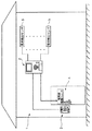
図1は、セキュリティシステム1の構成を示す図である。
【0027】
図1に示すように、セキュリティシステム1は、インターホン親機(以下、「親機」と略記する。)2と、親機2に接続されるドアホン子機(以下、「子機」と略記する。)3と、例えば玄関の扉を施錠/解錠する電気錠4と、複数の異常検出センサ5とを備えてなる。親機2は、例えば住宅におけるリビングに設置され、子機3は、表門に設置される。なお、図1では、子機3が1個の場合を示しているが、これに限定されず、子機3は、親機2の接続端子数に応じて複数個配設可能である。
【0028】
電気錠4は、詳細に図示しないが、例えば扉の適所に設けられ、突出位置と退避位置との間で移動可能とされ、家屋の壁の適所に形成された凹部とでロック機構を構成するロック部材と、ロック部材を突出位置と退避位置との間で駆動する後述の電気錠駆動ユニット50と、非接触タグ42(図5参照)に書き込まれたID情報を読み取るID情報読取装置とを備えており、読み取ったID情報が登録されているものであるとき、ロック部材を凹部に係合させて扉の開閉を規制(施錠)したり、ロック部材を凹部との係合を解除(解錠)させて扉を開閉可能としたりするように構成されている。
【0029】
なお、本実施形態では、ID情報読取装置は後述のID情報読取部38として子機3と一体化されている。
【0030】
異常検出センサ5は、例えば窓の開閉を検知する開閉検知センサ、窓ガラスへの衝撃やその破壊を検知する衝撃センサ、人間の存在を感知する人体感知センサ等であり、その機能に応じて住戸の適所に設置される。異常検出センサ5により異常が検出されると、親機2から例えば警備センターにその旨が報知される。
【0031】
図2は、親機2の構成を示すブロック図である。
【0032】
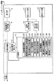
図2に示すように、親機2は、多重分離部6と、映像信号受信部7と、表示部8と、呼出信号検出部9と、音声送受話部10と、音入出力部11と、呼出音発生部12と、操作入力部13と、制御部14とを備えて構成される。
【0033】
多重分離部6は、子機3から送信され多重化されている映像変調信号、呼出信号及び音声信号を分離して、それぞれ映像信号受信部7、呼出信号検出部9及び音声送受話部10に出力すると共に、図略の直流電源及び音声送受話部10からの音声信号を多重化して子機3に送信する。
【0034】
映像信号受信部7は、映像変調信号を映像信号に復調して、表示部8に出力する回路である。
【0035】
表示部8は、主に映像信号受信部7からの映像信号を画像表示する回路である。表示部8は、例えば、CRTディスプレイ、液晶ディスプレイ(LCD)及び有機ELのディスプレイ等である。
【0036】
呼出信号検出部9は、多重分離部6で分離された呼出信号を検出して制御部14に出力する回路である。
【0037】
音声送受話部10は、多重分離部6で分離された子機3からの音声信号を復調し増幅してから音入出力部11に出力すると共に、音入出力部11から入力された音声信号を増幅しFM変調してから多重分離部6に出力する。そして、音声送受話部10は、親機2と子機3とが通話可能の状態で、音入出力部11からの音声信号と多重分離部6からの音声信号(ドアホン子機3からの音声信号)とのレベルを比較し、音入出力部11からの音声信号の方のレベルが大きい場合には入力音声信号を増幅・FM変調して多重分離部6に出力し、多重分離部6からの音声信号の方のレベルが大きい場合にはこの音声信号を復調・増幅して音入出力部11に出力する通話制御を行う。
【0038】
音入出力部11は、音声送受話部10から入力された音声信号を音声に変換して再生出力すると共に、主に居住者の音声を音声信号に変換して音声送受話部10に出力する。音入出力部11は、例えばマイクロホン等の音声を音声信号に変換する音入力部と、例えばスピーカ等の音声信号を音声に変換する音出力部とで構成される。あるいは、例えば、音声の入出力を兼ねたスピーカで構成される。
【0039】
呼出音発生部12は、制御部14からの出力に基づいて呼出音になる電気信号を発生させ、音入出力部11に出力する回路である。
【0040】
操作入力部13は、親機2を操作するための指示等を入力する回路であり、入力された指示は、制御部14に出力される。この操作入力部13を図3に基づいて説明する。
【0041】
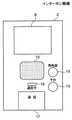
図3は、親機2の外観を示す図である。
【0042】
図3に示すように、親機2は、ケースの一方面の略中央部に音出力窓15が配置され、音出力窓15の上方に表示部8(図2の表示部8に相当する)が配置され、音出力窓15の下方に通話中であることを示すランプ16を介して通話釦17が配置される。音出力窓15は、親機2の内外で音を伝播させるためのものであり、例えばメッシュ状に孔を備えた開口である。
【0043】
図3には図示されていないが、音出力窓15の背面には、前述した音入出力部11の音出力部(例えばスピーカ)が配置される。一方、音入出力部11の音入力部(例えばマイクロホン)は、通話釦17の下部に配置される。
【0044】
通話釦17は、親機2と子機3との間で通話の開始及び終了をオン・オフするスイッチであり、通話釦17を操作することによって親機2が子機3と通話可能となり、通話釦17を再び操作することによって子機3との通話が終了される。
【0045】
音出力窓15、ランプ16及び通話釦17の側方には、施解錠ボタン18と予約ボタン19とが上下に配置されている。
【0046】
施解錠ボタン18は、電気錠4の施錠及び解錠を指示する入力を行うものであり、押圧操作されるたびに、電気錠4による施錠動作及び解錠動作が交互に行われる。
【0047】
ここで、セキュリティシステム1は、各異常検出センサ5を作動状態とし、侵入しようとする者の存在を検知するセキュリティモードを備えるが、従来では、室内に配置された所定の装置(例えば本実施形態の親機2に対応する装置)に対して所定の操作を行うと、直ちにこのセキュリティモードに設定されていた。
【0048】
しかし、この場合、居住者が住戸外に出て施錠するまでに、異常検出センサ5はすでに作動状態となっているから、それまでの居住者の行動によって異常検出センサ5が反応し、例えば警備センターに報知されることとなる。
【0049】
そこで、前述した所定の装置に対し所定の操作が行われた場合には、一定時間待機したのちにセキュリティモードに設定するように構成したものがある。
【0050】
しかし、この場合、その待機動作が終了するまでに居住者による施錠動作が完了すると、居住者は、セキュリティモードに設定されたか否かを確認するためには、待機しなければならない。
【0051】
このような不具合を解消するため、本実施形態のセキュリティシステム1においては、居住者が電気錠4を施錠するときにセキュリティモードに設定するように構成している。
【0052】
予約ボタン19は、セキュリティモードの設定を待機する待機モードに設定するためのボタンである。後述するように、この予約ボタン19が操作された場合であって、電気錠4が施錠されると、その施錠時にセキュリティモードに設定される。
【0053】
以上のように、操作入力部13は、通話釦17、施解錠ボタン18及び予約ボタン19で構成される。
【0054】
制御部14は、例えば制御プログラムを記憶するROMや一時的にデータを記憶するRAMからなる記憶部が内蔵されたマイクロコンピュータからなり、上述した親機2内の多重分離部6、呼出信号検出部9、呼出音発生部12及び操作入力部13の駆動を制御するものである。
【0055】
また、制御部14は、機能的に、施解錠制御部20と、施解錠実施信号受信部21と、照合結果信号受信部22と、モード設定部23と、設定信号送信部24と、解除信号送信部25と、表示制御部26と、報知音出力制御部27と、画像データ記憶部28と、報知音データ記憶部29とを有する。
【0056】
施解錠制御部20は、施解錠ボタン18が操作されたとき、待機モードに設定された状態で子機3から照合結果信号を受信したとき、及びセキュリティモードが解除されたときに、施錠指示信号又は解錠指示信号を電気錠駆動ユニット50に出力することにより、該電気錠駆動ユニット50によるロック機構の動作(施錠動作又は解錠動作)を制御するものである。
【0057】
施解錠実施信号受信部21は、電気錠駆動ユニット50から送信される施錠を実施した旨の施錠実施信号、及び解錠を実施した旨の解錠実施信号を受信するものである。
【0058】
照合結果信号受信部22は、子機3から送信される照合結果信号(後述するID情報と登録されているID情報とが一致した旨の一致信号)とID情報とを受信するものである。
【0059】
モード設定部23は、予約ボタン19が押圧操作されると、セキュリティモードの設定を待機する待機モードに設定し、電気錠駆動ユニット50から施錠実施信号を受信すると、セキュリティモードに設定し、セキュリティモードが設定されている状態で子機3から照合結果信号等を受信すると、セキュリティモードを解除するものである。
【0060】
設定信号送信部24は、モード設定部23によりセキュリティモードに設定されると、その旨を示す設定信号を子機3に送信するものである。
【0061】
解除信号送信部25は、モード設定部23によりセキュリティモードの設定が解除されると、その旨を示す解除信号を子機3に送信するものである。
【0062】
表示制御部26は、セキュリティモードが設定されていない場合に、照合結果信号受信部22により照合結果信号及びID情報が受信されると、施解錠操作を行った者を住戸内の居住者に知らせるべく、画像データ記憶部28からID情報に対応する画像データを読み出し、その画像データに係る画像を表示部8に表示させるものである。画像は、例えばID情報に対応する居住者の顔の画像や、その居住者の名前を示す画像などである。
【0063】
報知音出力制御部27は、セキュリティモードが設定されていない場合に、照合結果信号受信部22により照合結果信号が受信されると、施解錠操作を行った者を住戸内の居住者に知らせるべく、報知音データ記憶部29からID情報に対応する報知音データを読み出し、その報知音データに係る報知音を音入出力部11から出力させるものである。
【0064】
画像データ記憶部28は、ID情報に対応した画像データを記憶するものである。
【0065】
報知音データ記憶部29は、ID情報に対応した報知音データを記憶するものである。報知音は、例えば一定の周期で出力される電子音や、居住者の名前を知らせる音声、あるいは音楽などである。
【0066】
次に、子機3の構成について説明する。
【0067】
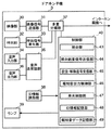
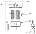
図4は、子機3の構成を示すブロック図、図5は、子機3の外観図である。
【0068】
図4に示すように、子機3は、撮像部30と、映像信号送信部31と、呼出釦32と、呼出信号発生部33と、音声入力部34と、音声送受話部35と、音声出力部36と、多重分離部37と、ID情報読取部38と、ランプ39と、制御部40とを備えて構成される。
【0069】
撮像部30は、被写体光像を光電変換して映像信号を出力する図略の撮像素子と、撮像素子の撮像面に被写体光像を結像させる光学系とを備えて構成される。撮像部30の映像信号は、映像信号送信部31に出力される。撮像素子は、受光した光をその光強度に従った電気信号に変換する複数の受光素子をマトリックス状に配置した光電変換素子であり、例えばCCD(Charge Coupled Device)やCMOS(Complementary Metal−Oxide Semiconductor)の固体撮像素子等である。
【0070】
図5に示すように、子機3は、ケースの一方面の略中央部に音出力窓41が配置され、音出力窓41の上方に撮像部30(図5では光学系の対物レンズのみ図示)が配置され、音出力窓41の下方にセキュリティモードの設定及び解除を行ったことを示すランプ39と呼出釦32とが配置される。音出力窓41は、子機3の内外で音を伝播させるためのものであり、例えば長尺状の孔を複数備えた開口である。
【0071】
図5には図示されていないが、音出力窓41の背面には、前述した音声出力部36(例えばスピーカ)が配置される。一方、音声入力部34(例えばマイクロホン)は、ランプ39の下部に配置される。
【0072】
また、音出力窓41の側方には、ID情報が書き込まれた非接触タグ42(例えばRFID(Radio Frequency Identification)タグ)の該ID情報を読み取るID情報読取部38が配置されている。ID情報読取部38は、非接触タグ42とで周知の電磁誘導式の施解錠システムを構成するものであり、ID情報読取部38は微弱電波を出力しており、このID情報読取部38に非接触タグ42を近づけると、非接触タグ42はID情報読取部38から出力される微弱電波を受信し、その電波により発生する起電力で非接触タグ42の動作電力が確保され、非接触タグ42に書き込まれたID等の情報がID情報読取部38に送信される。
【0073】
図4に戻り、映像信号送信部31は、入力された映像信号を変調して映像変調信号として多重分離部37に出力する回路である。
【0074】
呼出釦32は、親機2の音入出力部11から呼出音を鳴動させるための呼出信号を親機2に送信させるための回路であり、例えば、押釦スイッチ等である。訪問者は、この呼出釦32を操作することによって、住戸内の居住者に訪問者の存在があることを知らせる。
【0075】
呼出信号発生部33は、親機2の音入出力部11から呼出音を鳴動させるための呼出信号を生成し、生成した呼出信号を多重分離部37に出力する回路である。
【0076】
音声入力部34は、音を音声信号として電気信号に変換する回路であり、例えば、マイクロホンである。この音声信号は、音声入力部34から音声送受話部35を介して多重分離部37に出力される。訪問者は、音声を音声入力部34に入力することによって、親機2の居住者と通話する。
【0077】
音声送受話部35は、音声入力部34から入力された音声信号を増幅しFM変調してから多重分離部37に出力すると共に、多重分離部37から入力された親機2からの音声信号を復調し増幅してから音声出力部36に出力する。
【0078】
音声出力部36は、電気信号を音に変換する回路であり、例えば、スピーカである。親機2から送信された音声信号は、この音声出力部36で音声として再生され出力される。
【0079】
多重分離部37は、映像信号送信部31からの映像変調信号、呼出信号発生部33からの呼出信号、及び、音声送受話部35からの音声信号を多重化して親機2に送信する。
【0080】
ID情報読取部38は、図5に示すID情報読取部38に相当するものである。なお、例えば光等を用いて読み取る構成も採用可能である。
【0081】
ランプ39は、図5に示すランプ39に相当するものであり、例えばLED(light emitting diode)である。
【0082】
制御部40は、例えば制御プログラムを記憶するROMや一時的にデータを記憶するRAMからなる記憶部が内蔵されたマイクロコンピュータからなる。
【0083】
また、制御部40は、機能的に、照合部43と、照合結果信号送信部44と、設定/解除信号受信部45と、報知音出力制御部46と、発光制御部47と、ID情報記憶部48と、報知音データ記憶部49とを有する。
【0084】
照合部43は、ID情報読取部38により読み取られたID情報が、ID情報記憶部48に登録されたID情報と一致するか否かを照合するものである。
【0085】
照合結果信号送信部44は、ID情報読取部38により読み取られたID情報が、ID情報記憶部48に登録されたID情報と一致すると照合部43により判定されると、その旨を示す照合結果信号とID情報とを親機2に送信するものである。
【0086】
設定/解除信号受信部45は、親機2から送信されるセキュリティモードの設定を実施した旨の設定信号、及びその設定の解除を実施した旨の解除信号を受信するものである。
【0087】
報知音出力制御部46は、設定/解除信号受信部45により前述の設定信号または解除信号が受信されると、報知音データ記憶部49に記憶されている報知音データを読み出し、この報知音データに係る報知音を音声出力部36から出力させるものである。
【0088】
発光制御部47は、設定/解除信号受信部45により前述の設定信号または解除信号が受信されると、ランプ39の点灯制御を行うものである。発光制御部47は、例えば、設定/解除信号受信部45により前述の設定信号が受信されたとき(セキュリティモードに設定されたとき)にはランプ39を点灯させ、解除信号が受信されたとき(セキュリティモードが解除されたとき)には、ランプ39を消灯させる。
【0089】
報知音データ記憶部49は、セキュリティモードが設定または解除されたときに出力する報知音の報知音データを記憶するものである。報知音は、例えば一定の周期で出力される電子音や、居住者の名前を知らせる音声、あるいは音楽などである。
【0090】
次に、電気錠駆動ユニット50の構成について説明する。
【0091】
図6は、電気錠駆動ユニット50の構成を示すブロック図である。
【0092】
図6に示すように、電気錠駆動ユニット50は、施錠指示信号受信部51と、解錠指示信号受信部52と、駆動部53と、施錠実施信号送信部54と、解錠実施信号送信部55とを備える。
【0093】
施錠指示信号受信部51は、親機2から送信される施錠指示信号を受信するものであり、解錠指示信号受信部52は、親機2から送信される解錠指示信号を受信するものである。
【0094】
駆動部53は、施錠指示信号受信部51により施錠指示信号が受信されると、前述したロック機構にロック動作を行わせて扉の開閉を規制し、解錠指示信号受信部52により解錠指示信号が受信されると、前述したロック機構にロック動作の解除を行わせて扉の開閉規制を解除するものである。
【0095】
施錠実施信号送信部54は、駆動部53により施錠動作が完了すると、その旨を示す施錠実施信号を親機2に送信するものである。
【0096】
解錠実施信号送信部55は、駆動部53により解錠動作が完了すると、その旨を示す解錠実施信号を親機2に送信するものである。
【0097】
次に、セキュリティシステム1のセキュリティモード設定処理を説明する。
【0098】
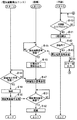
図7は、セキュリティシステム1のセキュリティモード設定処理を示すフローチャートである。
【0099】
図7に示すように、予約ボタン19が押圧操作される(ステップ♯1でYES)と、親機2において、モード設定部23は、当該システム1を待機モードに設定する(ステップ♯2)。
【0100】
その後、子機3において、非接触タグ42がID情報読取部38に近づけられてID情報が入力される(ステップ♯3でYES)と、照合部43は、この読み取ったID情報の照合を行う(ステップ♯4)。その照合の結果、登録されているものであるとき(ステップ♯5でYES)、照合結果信号送信部44は、照合結果信号及びID情報を親機2に送信し(ステップ♯6)、登録されているものでないとき(ステップ♯5でNO)、報知音出力制御部46は、音声出力部36からエラー音を出力させる(ステップ♯7)。
【0101】
親機2において、照合結果信号受信部22が、所定時間経過しても照合結果信号及びID情報を子機3から受信しないとき(ステップ♯8でNO、♯9でYES)、モード設定部23は、セキュリティモードに設定し(ステップ♯15)、所定時間以内に照合結果信号及びID情報を子機3から受信する(ステップ♯8でYES)と、施解錠制御部20は、施錠指示信号を電気錠駆動ユニット50に送信する(ステップ♯10)。なお、所定時間経過しても照合結果信号等を子機3から受信しないとき、セキュリティモードに設定するのは、居住者が施錠するのを忘れていることが考えられ、この場合の防犯性を保持するためである。
【0102】
電気錠駆動ユニット50において、施錠指示信号受信部51は、親機2から施錠指示信号を受信する(ステップ♯11でYES)と、駆動部53は、ロック機構にロック動作を行わせて扉の開閉を規制し(ステップ♯12)、施錠実施信号送信部54は、駆動部53により施錠動作が完了した旨を示す施錠実施信号を親機2に送信する(ステップ♯13)。
【0103】
親機2において、施解錠実施信号受信部21は、電気錠駆動ユニット50から施錠実施信号を受信する(ステップ♯14でYES)と、モード設定部23は、当該システム1をセキュリティモードに設定し(ステップ♯15)、設定信号送信部24は、セキュリティモードを設定した旨の設定信号を子機3に送信する(ステップ♯16)。
【0104】
子機3において、設定/解除信号受信部45は、親機2から設定信号を受信する(ステップ♯17でYES)と、報知音出力制御部46は、音声出力部36から報知音を出力させるとともに、発光制御部47は、ランプ39を点灯させる(ステップ♯18)。これにより、居住者は、セキュリティモードに設定されたことを確認することができる。
【0105】
次に、セキュリティシステム1のセキュリティモード解除処理を説明する。
【0106】
図8は、セキュリティシステム1のセキュリティモード解除処理を示すフローチャートである。
【0107】
図8に示すように、非接触タグ42がID情報読取部38に近づけられてID情報が入力される(ステップ♯20でYES)と、照合部43は、この読み取ったID情報の照合を行う(ステップ♯21)。その照合の結果、登録されているものであるとき(ステップ♯22でYES)、照合結果信号送信部44は、照合結果信号とID情報とを親機2に送信し(ステップ♯23)、登録されているものでないとき(ステップ♯22でNO)、報知音出力制御部46は、音声出力部36からエラー音を出力させる(ステップ♯24)。
【0108】
親機2において、照合結果信号受信部22は、照合結果信号とID情報とを子機3から受信する(ステップ♯25でYES)と、モード設定部23は、セキュリティモードの設定を解除し(ステップ♯26)、解除信号送信部25は、セキュリティモードを解除した旨を示す解除信号を子機3に送信する(ステップ♯27)。
【0109】
子機3において、設定/解除信号受信部45は、親機2から解除信号を受信する(ステップ♯28でYES)と、報知音出力制御部46は、音声出力部36から報知音を出力させるとともに、発光制御部47は、ランプ39を点灯させる(ステップ♯29)。これにより、居住者は、セキュリティモードの設定が解除されたことを確認することができる。
【0110】
また、親機2において、ステップ♯27の処理に続き、施解錠制御部20は、解錠指示信号を電気錠駆動ユニット50に送信する(ステップ♯30)。
【0111】
電気錠駆動ユニット50において、解錠指示信号受信部52は、親機2から送信される解錠指示信号を受信する(ステップ♯31でYES)と、駆動部53は、ロック機構にロック動作の解除を行わせて扉の開閉規制を解除(ステップ♯32)し、解錠実施信号送信部55は、駆動部53による解錠動作が完了した旨を示す解錠実施信号を親機2に送信する(ステップ♯33)。
【0112】
親機2において、施解錠実施信号受信部21は、電気錠駆動ユニット50から解錠実施信号を受信する(ステップ♯34でYES)と、施解錠制御部20は、電気錠4が解錠状態であることを認識して終了する(ステップ♯35)。
【0113】
次に、セキュリティモードが設定されていない場合の施解錠処理を説明する。
【0114】
図9は、セキュリティモードが設定されていない場合の解錠処理を示すフローチャートである。
【0115】
図9に示すように、非接触タグ42がID情報読取部38に近づけられてID情報が入力される(ステップ♯40でYES)と、照合部43は、この読み取ったID情報の照合を行う(ステップ♯41)。その照合の結果、登録されているものであるとき(ステップ♯42でYES)、照合結果信号送信部44は、照合結果信号とID情報とを親機2に送信し(ステップ♯43)、登録されているものでないとき(ステップ♯42でNO)、報知音出力制御部46は、音声出力部36からエラー音を出力させる(ステップ♯44)。
【0116】
親機2において、照合結果信号受信部22は、照合結果信号とID情報とを子機3から受信する(ステップ♯45でYES)と、表示制御部26は、そのID情報に対応する画像データに係る画像を表示部8に表示させるとともに、報知音出力制御部27は、上記ID情報に対応する報知音データに係る報知音を音入出力部11から出力させる(ステップ♯46)。
【0117】
そして、施解錠制御部20は、解錠指示信号を電気錠駆動ユニット50に送信する(ステップ♯47)。
【0118】
電気錠駆動ユニット50において、解錠指示信号受信部52は、親機2から送信される解錠指示信号を受信する(ステップ♯48でYES)と、駆動部53は、ロック機構によるロック動作の解除を行わせて扉の開閉規制を解除(ステップ♯49)し、解錠実施信号送信部55は、駆動部53による解錠動作が完了した旨を示す解錠実施信号を親機2に送信する(ステップ♯50)。
【0119】
親機2において、施解錠実施信号受信部21は、電気錠駆動ユニット50から解錠実施信号を受信する(ステップ♯51でYES)と、施解錠制御部20は、電気錠4が解錠状態であることを認識して終了する(ステップ♯52)。
【0120】
なお、セキュリティモードが設定されていない場合の施錠処理は、図9に示すステップ♯47〜♯51の処理において、解錠に関わる信号の授受及び解錠動作が、施錠に関わる信号の授受及び施錠動作に変わるのみで、それ以外の処理については図9に示す処理と同様である。
【0121】
このように、予約ボタン19が操作されると、セキュリティモードの設定を待機し、居住者が電気錠4を施錠するときにセキュリティモードに設定するように構成したので、従来の構成において生じていた待機時間や誤報知を防止することができるとともに、この予約ボタン19の操作によって居住者が必要と考えるときにのみセキュリティモードに設定することができる。
【0122】
また、居住者により解錠操作が行われると、電気錠4の解錠とセキュリティモードの解除とが行われるようにしたので、電気錠4の解錠とセキュリティモードの解除とが異なる操作で実行される構成に比して、操作の手間を省くことができる。
【0123】
また、セキュリティモードの設定時及びその設定解除時に、子機3において、報知音を出力したり、ランプ39を点灯させたりしたので、セキュリティモードの設定動作及びその設定解除動作が行われたことを確認することができる。
【0124】
また、セキュリティモードが設定されていない場合において、電気錠4に対する施解錠操作が行われると、読み取ったID情報に対応する画像を表示部8に表示したり、報知音を出力したりするようにしたので、施解錠操作を行っている者を、室内にいる者に知らせることができる。
【0125】
なお、本発明は、上記実施形態に限らず、次の変形形態(1)〜(3)が採用可能である。
【0126】
(1)上記実施形態では、セキュリティモードに設定されたときにはランプ39を点灯させ、セキュリティモードが解除されたときには、ランプ39を消灯させるようにしたが、セキュリティモードの設定及びその解除が行われたときに、ランプ39を点滅させるようにしてもよいし、ランプ39が複数備えられている場合には、セキュリティモードに設定されているときと、セキュリティモードの設定が解除されているときとで、発光させるランプ39の数を変えたり、発光色を変えたりするなどして、発光形態を異ならせるようにしてもよい。
【0127】
(2)上記実施形態では、ID情報の照合機能を子機3に搭載したが、親機2に搭載するようにしてもよい。
【0128】
この場合、親機2に、予めID情報を記憶するID情報記憶部を備え、ID情報読取部38で読み取られたID情報を子機3から親機2に送信し、親機2において、この送信されたID情報が上記のID情報記憶部に登録されているか否かを照合する。そして、照合の結果、ID情報がこのID情報記憶部に登録されている場合には、図7のステップ♯11や図8のステップ♯26等の処理を行うようにすればよい。
【0129】
(3)電気錠における照合対象の情報を読み取る装置として、前述したものに限らず、例えば、子機3に、もしくは子機3の近傍に、番号キーを含む複数の操作キーを備えた入力装置を備え、この入力装置により暗証番号等を居住者により入力する装置でもよく、要は、照合対象の情報が取得できるものであれば何でもよい。
【0130】
【発明の効果】
以上のように、インターホン親機の操作部が操作されると、ロック機構が駆動部によりロック状態に駆動されるまでセキュリティモードの設定動作を待機し、ロック機構が駆動部によりロック状態に駆動されるとセキュリティモードに設定するようにしたので、従来のような待機時間の発生や誤報知を防止し、且つ居住者が必要と考えて操作部が操作されたときにのみ防犯用の異常検知を行うモードに設定できるセキュリティシステムを構築することができる。
【図面の簡単な説明】
【図1】セキュリティシステムの構成を示す図である。
【図2】親機の構成を示すブロック図である。
【図3】親機の外観を示す図である。
【図4】子機の構成を示すブロック図、
【図5】子機の外観図である。
【図6】電気錠駆動ユニットの構成を示すブロック図である。
【図7】セキュリティシステムのセキュリティモード設定処理を示すフローチャートである。
【図8】セキュリティシステムのセキュリティモード解除処理を示すフローチャートである。
【図9】セキュリティモードが設定されていない場合の解錠処理を示すフローチャートである。
【符号の説明】
1 セキュリティシステム
2 インターホン親機
3 ドアホン子機
4 電気錠
5 異常検出センサ
14 制御部
19 予約ボタン
20 施解錠制御部
21 施解錠実施信号受信部
22 照合結果信号受信部
23 モード設定部
24 設定信号送信部
25 解除信号送信部
26 表示制御部
27 報知音出力制御部
28 画像データ記憶部
29 報知音データ記憶部
38 ID情報読取部
39 ランプ
43 照合部
44 照合結果信号送信部
45 設定/解除信号受信部
46 報知音出力制御部
47 発光制御部
48 ID情報記憶部
49 報知音データ記憶部
50 電気錠駆動ユニット
51 施錠指示信号受信部
52 解錠指示信号受信部
53 駆動部
54 施錠実施信号送信部
55 解錠実施信号送信部[0001]
TECHNICAL FIELD OF THE INVENTION
The present invention belongs to the technical field of a security system constructed in a house or a building, and particularly relates to a system provided with an electric lock that automatically locks and unlocks a door and the like according to a command by an electric signal.
[0002]
[Prior art]
As a security system built in a house or a building, for example, there is one described in
[0003]
This
[0004]
[Patent Document 1]
JP-A-5-321523
[0005]
[Problems to be solved by the invention]
However, in
[0006]
On the other hand, if an operation device for performing an input for setting the alert mode is provided in the room and the operation device is operated so that the alert mode is set immediately, the resident goes out of the dwelling unit. By the time the lock is locked, the security sensor has already been activated, and the occupant's action up to that time will cause the security sensor to react and be notified to the security center that an abnormality has occurred, for example.
[0007]
In addition, when an operation device for performing an input for setting the alert mode is provided in the room, and after operating this operation device, the device is configured to wait for a predetermined time and then set the alert mode, the above-described operation is performed. Such false alarms are reduced, but if the locking operation by the occupant is completed before the standby operation is completed, the occupant must wait in order to check whether or not the alert mode has been set. .
[0008]
The present invention has been made in view of such circumstances, and prevents the occurrence of the above-described waiting time and erroneous notification, and detects anomaly for crime prevention only when the resident considers it necessary. It is an object of the present invention to provide a security system that can be set to the following.
[0009]
[Means for Solving the Problems]
According to the first aspect of the present invention, there is provided a security mode which is communicably connected to an electric lock which locks and unlocks a door, and causes one or a plurality of abnormality detection sensors for detecting abnormality for crime prevention to perform the abnormality detection. Setting, and a mode setting unit for canceling the security mode; an operation unit for inputting an instruction to wait for the setting of the security mode to the mode setting unit; and a locking operation or an unlocking operation for the electric lock. When the operation unit is operated, the mode setting unit controls the operation of the electric lock, and when the operation unit is operated, the mode setting unit controls the security mode until the locking operation by the electric lock is performed. The intercom master unit waits for a setting operation and sets the security mode when the locking operation by the electric lock is performed.
[0010]
According to the present invention, when the operation unit is operated, the mode setting unit waits for the setting operation of the security mode until the locking operation by the electric lock is performed, and sets the security mode when the locking operation by the electric lock is performed. Therefore, it is necessary to set the mode to prevent the occurrence of the standby time and erroneous notification as in the past, and detect the abnormality for crime prevention only when the operation unit is operated by the occupants as necessary. Can be.
[0011]
According to a second aspect of the present invention, in the intercom master unit according to the first aspect, the mode setting unit releases the security mode when an unlocking operation by the electric lock is performed. It is.
[0012]
According to the present invention, when the unlocking operation by the electric lock is performed, the security mode is released, so that the unlocking of the electric lock and the release of the security mode are performed by different operations. , Operation can be saved.
[0013]
According to a third aspect of the present invention, in the intercom master unit according to the first or second aspect, when the security mode is set and / or canceled by the mode setting unit, the intercom master unit has a notifying unit for notifying the user. It is characterized by the following.
[0014]
According to the present invention, when the security mode is set and / or canceled, the notifying unit that notifies the user of the setting is provided, so that the resident can confirm that the security mode has been set or canceled. be able to.
[0015]
According to a fourth aspect of the present invention, in the intercom master unit according to the third aspect, the notification unit is a sound output unit that outputs a sound.
[0016]
According to the present invention, the notification unit is a sound output unit that outputs a sound, so that the occupant can audibly confirm that the security mode has been set or canceled.
[0017]
According to a fifth aspect of the present invention, in the interphone master unit according to the third aspect, the notification unit is a light emitting unit that outputs light.
[0018]
According to the present invention, since the notification unit is a light emitting unit that outputs light, the resident can visually confirm that the security mode has been set or canceled.
[0019]
According to a sixth aspect of the present invention, in the intercom master unit according to any one of the first to fifth aspects, the electric lock takes in information relating to a collation target and performs a locking operation or an unlocking operation according to the collation result. In the case, when a storage unit that stores information related to a collation target and an image in advance in association with each other, and when the information related to the collation target captured by the electric lock is stored in the storage unit, the storage unit corresponds to the collation target. And an image display unit for displaying an image to be displayed.
[0020]
According to the present invention, when the information relating to the collation target taken into the electric lock is stored in the storage unit, an image corresponding to the collation target is displayed on the image display unit. The person performing the unlocking operation can be visually notified to the person in the room.
[0021]
According to a seventh aspect of the present invention, in the intercom master unit according to any one of the first to sixth aspects, the electric lock takes in information relating to a collation target and performs a locking operation or an unlocking operation according to the collation result. A storage unit that stores information relating to the collation target and the notification sound data in association with each other in advance, and when the information relating to the collation target taken into the electric lock is stored in the storage unit, And a notification sound output unit that outputs a notification sound based on the notification sound data corresponding to.
[0022]
According to the present invention, when the information relating to the verification target captured in the electric lock is stored in the storage unit, the notification sound based on the notification sound data corresponding to the verification target is output by the notification sound output unit. Therefore, the person who is performing the locking operation or the unlocking operation can be visually notified to the person in the room.
[0023]
The invention according to
[0024]
According to the present invention, when the operation unit of the intercom master unit is operated, the operation of setting the security mode is waited until the locking operation by the electric lock is performed, and the security mode is set when the locking operation by the electric lock is performed. As a result, a security system that can prevent the occurrence of a standby time and erroneous notification as in the related art, and can be set to a mode in which an abnormality detection for crime prevention is detected only when the operation unit is operated by the occupant as necessary. Can be constructed.
[0025]
BEST MODE FOR CARRYING OUT THE INVENTION
Hereinafter, embodiments according to the present invention will be described with reference to the drawings.
[0026]
FIG. 1 is a diagram illustrating a configuration of the
[0027]
As shown in FIG. 1, the
[0028]
Although not shown in detail, the
[0029]
In the present embodiment, the ID information reading device is integrated with the
[0030]
The
[0031]
FIG. 2 is a block diagram showing a configuration of the
[0032]
As shown in FIG. 2,
[0033]
The
[0034]
The video
[0035]
The
[0036]
The paging
[0037]
The voice transmission /
[0038]
The sound input /
[0039]
The ringing
[0040]
The
[0041]
FIG. 3 is a diagram illustrating an appearance of the
[0042]
As shown in FIG. 3,
[0043]
Although not shown in FIG. 3, a sound output unit (for example, a speaker) of the above-described sound input /
[0044]
The
[0045]
A lock /
[0046]
The locking / unlocking
[0047]
Here, the
[0048]
However, in this case, the
[0049]
Therefore, there is a configuration in which when a predetermined operation is performed on the above-described predetermined device, the security mode is set after waiting for a predetermined time.
[0050]
However, in this case, if the locking operation by the occupant is completed before the standby operation is completed, the occupant must wait in order to check whether or not the security mode has been set.
[0051]
In order to solve such a problem, the
[0052]
The
[0053]
As described above, the
[0054]
The
[0055]
Further, the
[0056]
The locking / unlocking
[0057]
The lock execution
[0058]
The matching result
[0059]
When the
[0060]
When the security mode is set by the
[0061]
When the setting of the security mode is released by the
[0062]
When the collation result signal and the ID information are received by the collation result
[0063]
When the security mode is not set and the matching result signal is received by the matching result
[0064]
The image
[0065]
The notification sound
[0066]
Next, the configuration of the
[0067]
FIG. 4 is a block diagram showing the configuration of the
[0068]
As shown in FIG. 4, the
[0069]
The
[0070]
As shown in FIG. 5, the
[0071]
Although not shown in FIG. 5, the above-described sound output unit 36 (for example, a speaker) is disposed on the back of the
[0072]
An ID
[0073]
Returning to FIG. 4, the video
[0074]
The
[0075]
The ringing
[0076]
The
[0077]
The voice transmitting / receiving
[0078]
The
[0079]
The
[0080]
The ID
[0081]
The
[0082]
The
[0083]
The
[0084]
The collating
[0085]
If the
[0086]
The setting / cancellation
[0087]
When the setting signal or the release signal is received by the setting / release
[0088]
The light
[0089]
The notification sound
[0090]
Next, the configuration of the electric
[0091]
FIG. 6 is a block diagram showing a configuration of the electric
[0092]
As shown in FIG. 6, the electric
[0093]
The locking instruction
[0094]
When the locking instruction signal is received by the locking instruction
[0095]
When the locking operation is completed by the
[0096]
When the unlocking operation is completed by the
[0097]
Next, a security mode setting process of the
[0098]
FIG. 7 is a flowchart showing a security mode setting process of the
[0099]
As shown in FIG. 7, when the
[0100]
Thereafter, in the
[0101]
In the
[0102]
In the electric
[0103]
In
[0104]
In
[0105]
Next, the security mode release processing of the
[0106]
FIG. 8 is a flowchart showing the security mode release processing of the
[0107]
As shown in FIG. 8, when the
[0108]
In
[0109]
In
[0110]
Further, in
[0111]
In electric
[0112]
In
[0113]
Next, the locking / unlocking process when the security mode is not set will be described.
[0114]
FIG. 9 is a flowchart showing the unlocking process when the security mode is not set.
[0115]
As shown in FIG. 9, when the
[0116]
In
[0117]
Then, locking / unlocking
[0118]
In electric
[0119]
In
[0120]
Note that the locking process in the case where the security mode is not set is performed in the processes of steps # 47 to # 51 shown in FIG. Only the operation is changed, and the other processing is the same as the processing shown in FIG.
[0121]
Thus, when the
[0122]
Further, when the occupant performs the unlocking operation, the
[0123]
Further, at the time of setting the security mode and at the time of canceling the setting, the
[0124]
In addition, when the security mode is not set, when the locking / unlocking operation on the
[0125]
The present invention is not limited to the above embodiment, and the following modifications (1) to (3) can be adopted.
[0126]
(1) In the above embodiment, the
[0127]
(2) In the above embodiment, the collation function of the ID information is mounted on the
[0128]
In this case, the
[0129]
(3) The device for reading the information to be verified in the electric lock is not limited to the device described above. For example, an input device provided with a plurality of operation keys including a number key in or near the
[0130]
【The invention's effect】
As described above, when the operation unit of the main unit of the intercom is operated, the operation of setting the security mode is waited until the lock mechanism is driven to the locked state by the drive unit, and the lock mechanism is driven to the locked state by the drive unit. In this case, the security mode is set, preventing the occurrence of a standby time and false notification as in the past, and detecting anomalies for crime prevention only when the operation unit is operated by the occupant as necessary. It is possible to build a security system that can be set to the mode in which it is performed.
[Brief description of the drawings]
FIG. 1 is a diagram showing a configuration of a security system.
FIG. 2 is a block diagram illustrating a configuration of a master unit.
FIG. 3 is a diagram showing an appearance of a master unit.
FIG. 4 is a block diagram showing a configuration of a slave unit.
FIG. 5 is an external view of a slave unit.
FIG. 6 is a block diagram illustrating a configuration of an electric lock driving unit.
FIG. 7 is a flowchart showing a security mode setting process of the security system.
FIG. 8 is a flowchart showing security mode release processing of the security system.
FIG. 9 is a flowchart showing an unlocking process when the security mode is not set.
[Explanation of symbols]
1 Security system
2 Intercom master unit
3 door phone cordless handset
4 Electric lock
5 Abnormality detection sensor
14 Control unit
19 Reservation button
20 Locking / unlocking control section
21 Locking / unlocking signal receiving section
22 Matching result signal receiving section
23 Mode setting section
24 setting signal transmission section
25 Release signal transmitter
26 Display control unit
27 Notification sound output control unit
28 Image data storage
29 Notification sound data storage
38 ID information reading unit
39 lamp
43 Collation unit
44 verification result signal transmission section
45 Setting / cancellation signal receiving section
46 Notification sound output control unit
47 Emission control unit
48 ID information storage unit
49 Notification sound data storage unit
50 Electric lock drive unit
51 Locking instruction signal receiving unit
52 Unlocking instruction signal receiving unit
53 drive unit
54 Locking signal transmission unit
55 Unlock execution signal transmission unit
Claims (8)
防犯用の異常検出を行う1または複数の異常検出センサに該異常検出を行わせるセキュリティモードの設定と、該セキュリティモードの解除とを行うモード設定部と、
前記モード設定部に前記セキュリティモードの設定を待機させる指示を入力するための操作部と、
前記電気錠に対する施錠操作または解錠操作が行われると、前記電気錠の動作を制御する施解錠制御部とを備え、
前記モード設定部は、前記操作部が操作されると、前記電気錠による施錠動作が行われるまで前記セキュリティモードの設定動作を待機し、前記電気錠による施錠動作が行われると前記セキュリティモードに設定することを特徴とするインターホン親機。It is communicably connected to an electric lock that locks and unlocks the door,
A mode setting unit for setting a security mode for causing one or more abnormality detection sensors for performing abnormality detection for crime prevention to perform the abnormality detection, and for canceling the security mode;
An operation unit for inputting an instruction to wait for the setting of the security mode in the mode setting unit,
When a locking operation or an unlocking operation is performed on the electric lock, the lock operation includes an unlocking control unit that controls the operation of the electric lock,
When the operation unit is operated, the mode setting unit waits for the setting operation of the security mode until the locking operation by the electric lock is performed, and sets the security mode when the locking operation by the electric lock is performed. Intercom master unit characterized by doing.
前記インターホン親機は、請求項1ないし7のいずれかに記載のインターホン親機であり、
前記ドアホン子機は、施錠操作または解錠操作により入力される照合対象の情報を取得する情報取得部を備え、
前記電気錠は、照合対象に係る情報を取り込みその照合結果に応じて施錠動作または解錠動作を行うものである
を備えることを特徴とするセキュリティシステム。In a security system configured to be able to communicate with one or more abnormality detection sensors for performing security abnormality detection, an intercom master unit, a door phone slave unit, and an electric lock,
The intercom master unit is the intercom master unit according to any one of claims 1 to 7,
The doorphone slave unit includes an information acquisition unit that acquires information to be collated by a locking operation or an unlocking operation,
The security system according to claim 1, wherein the electric lock is configured to take in information related to a collation target and perform a locking operation or an unlocking operation according to a result of the collation.
Priority Applications (1)
| Application Number | Priority Date | Filing Date | Title |
|---|---|---|---|
| JP2003149857A JP3994919B2 (en) | 2003-05-27 | 2003-05-27 | Security system |
Applications Claiming Priority (1)
| Application Number | Priority Date | Filing Date | Title |
|---|---|---|---|
| JP2003149857A JP3994919B2 (en) | 2003-05-27 | 2003-05-27 | Security system |
Publications (2)
| Publication Number | Publication Date |
|---|---|
| JP2004355152A true JP2004355152A (en) | 2004-12-16 |
| JP3994919B2 JP3994919B2 (en) | 2007-10-24 |
Family
ID=34045841
Family Applications (1)
| Application Number | Title | Priority Date | Filing Date |
|---|---|---|---|
| JP2003149857A Expired - Fee Related JP3994919B2 (en) | 2003-05-27 | 2003-05-27 | Security system |
Country Status (1)
| Country | Link |
|---|---|
| JP (1) | JP3994919B2 (en) |
Cited By (11)
| Publication number | Priority date | Publication date | Assignee | Title |
|---|---|---|---|---|
| JP2007162308A (en) * | 2005-12-13 | 2007-06-28 | Miwa Lock Co Ltd | Electric lock system |
| JP2007162222A (en) * | 2005-12-09 | 2007-06-28 | Alpha Corp | Door lock control device |
| JP2008077161A (en) * | 2006-09-19 | 2008-04-03 | Aiphone Co Ltd | Security intercom equipment |
| JP2009193537A (en) * | 2008-02-18 | 2009-08-27 | Panasonic Electric Works Co Ltd | Security intercom system |
| JP2010035128A (en) * | 2008-06-25 | 2010-02-12 | Panasonic Electric Works Co Ltd | Intercom system |
| JP2010108461A (en) * | 2008-10-28 | 2010-05-13 | Yoshimasa Taguchi | Crime prevention entrance slave unit with warning light |
| JP2010226347A (en) * | 2009-03-23 | 2010-10-07 | Panasonic Electric Works Co Ltd | Intercom system |
| JP2013065329A (en) * | 2012-11-13 | 2013-04-11 | Toyota Home Kk | Crime prevention device for building and building including the same |
| JP2019079408A (en) * | 2017-10-26 | 2019-05-23 | 富士ゼロックス株式会社 | Device, management system, and program |
| WO2020129580A1 (en) * | 2018-12-21 | 2020-06-25 | パナソニックIpマネジメント株式会社 | Intercom vestibule device, intercom system, information terminal, reporting method, and program |
| JP2021061552A (en) * | 2019-10-08 | 2021-04-15 | パナソニックIpマネジメント株式会社 | Intercom system |
-
2003
- 2003-05-27 JP JP2003149857A patent/JP3994919B2/en not_active Expired - Fee Related
Cited By (12)
| Publication number | Priority date | Publication date | Assignee | Title |
|---|---|---|---|---|
| JP2007162222A (en) * | 2005-12-09 | 2007-06-28 | Alpha Corp | Door lock control device |
| JP2007162308A (en) * | 2005-12-13 | 2007-06-28 | Miwa Lock Co Ltd | Electric lock system |
| JP2008077161A (en) * | 2006-09-19 | 2008-04-03 | Aiphone Co Ltd | Security intercom equipment |
| JP2009193537A (en) * | 2008-02-18 | 2009-08-27 | Panasonic Electric Works Co Ltd | Security intercom system |
| JP2010035128A (en) * | 2008-06-25 | 2010-02-12 | Panasonic Electric Works Co Ltd | Intercom system |
| JP2010108461A (en) * | 2008-10-28 | 2010-05-13 | Yoshimasa Taguchi | Crime prevention entrance slave unit with warning light |
| JP2010226347A (en) * | 2009-03-23 | 2010-10-07 | Panasonic Electric Works Co Ltd | Intercom system |
| JP2013065329A (en) * | 2012-11-13 | 2013-04-11 | Toyota Home Kk | Crime prevention device for building and building including the same |
| JP2019079408A (en) * | 2017-10-26 | 2019-05-23 | 富士ゼロックス株式会社 | Device, management system, and program |
| JP7155508B2 (en) | 2017-10-26 | 2022-10-19 | 富士フイルムビジネスイノベーション株式会社 | Equipment, management system and program |
| WO2020129580A1 (en) * | 2018-12-21 | 2020-06-25 | パナソニックIpマネジメント株式会社 | Intercom vestibule device, intercom system, information terminal, reporting method, and program |
| JP2021061552A (en) * | 2019-10-08 | 2021-04-15 | パナソニックIpマネジメント株式会社 | Intercom system |
Also Published As
| Publication number | Publication date |
|---|---|
| JP3994919B2 (en) | 2007-10-24 |
Similar Documents
| Publication | Publication Date | Title |
|---|---|---|
| JP3994919B2 (en) | Security system | |
| KR100900027B1 (en) | Emergency call monitoring system and contingency monitoring method in multi-family housing complex | |
| JP5054566B2 (en) | Residential security system | |
| JP5074857B2 (en) | Electric lock system | |
| JP2011155416A (en) | Interphone system | |
| JP2008059327A (en) | Security intercom system | |
| JP5107866B2 (en) | Nurse call system | |
| JP4599987B2 (en) | Nameplate display device | |
| JP2005056261A (en) | Home security system | |
| JP2003303379A (en) | Security device and security system | |
| JP3856017B2 (en) | Integrated call and monitoring system for apartment houses | |
| JP2010282571A (en) | Security system | |
| JP2006033558A (en) | Intercom system | |
| JP5066230B2 (en) | Nameplate display device | |
| JP2008211501A (en) | Interphone system | |
| KR100350347B1 (en) | Wireless remote double locking method of electronic door lock | |
| JP2006238096A (en) | Intercom system | |
| JP2011035538A (en) | Intercom system | |
| KR20110055766A (en) | Emergency call monitoring system in multi-family housing complex and emergency call monitoring method | |
| JP2005094621A (en) | Interphone system | |
| JP5261241B2 (en) | Intercom system | |
| KR200318523Y1 (en) | Digital Door Lock with Wireless Video Communication | |
| JP2005204142A (en) | Wireless door phone device | |
| KR19990068792A (en) | Device for being united a video door-phone and door-lock | |
| JP2000054702A (en) | Door-electric lock linkage type interphone equipment |
Legal Events
| Date | Code | Title | Description |
|---|---|---|---|
| A621 | Written request for application examination |
Free format text: JAPANESE INTERMEDIATE CODE: A621 Effective date: 20050308 |
|
| A977 | Report on retrieval |
Free format text: JAPANESE INTERMEDIATE CODE: A971007 Effective date: 20060821 |
|
| A131 | Notification of reasons for refusal |
Free format text: JAPANESE INTERMEDIATE CODE: A131 Effective date: 20060912 |
|
| A131 | Notification of reasons for refusal |
Free format text: JAPANESE INTERMEDIATE CODE: A131 Effective date: 20070213 |
|
| A521 | Written amendment |
Free format text: JAPANESE INTERMEDIATE CODE: A523 Effective date: 20070416 |
|
| TRDD | Decision of grant or rejection written | ||
| A01 | Written decision to grant a patent or to grant a registration (utility model) |
Free format text: JAPANESE INTERMEDIATE CODE: A01 Effective date: 20070710 |
|
| A61 | First payment of annual fees (during grant procedure) |
Free format text: JAPANESE INTERMEDIATE CODE: A61 Effective date: 20070723 |
|
| FPAY | Renewal fee payment (prs date is renewal date of database) |
Free format text: PAYMENT UNTIL: 20100810 Year of fee payment: 3 |
|
| R150 | Certificate of patent (=grant) or registration of utility model |
Free format text: JAPANESE INTERMEDIATE CODE: R150 |
|
| FPAY | Renewal fee payment (prs date is renewal date of database) |
Free format text: PAYMENT UNTIL: 20100810 Year of fee payment: 3 |
|
| S533 | Written request for registration of change of name |
Free format text: JAPANESE INTERMEDIATE CODE: R313533 |
|
| FPAY | Renewal fee payment (prs date is renewal date of database) |
Free format text: PAYMENT UNTIL: 20100810 Year of fee payment: 3 |
|
| R350 | Written notification of registration of transfer |
Free format text: JAPANESE INTERMEDIATE CODE: R350 |
|
| FPAY | Renewal fee payment (prs date is renewal date of database) |
Free format text: PAYMENT UNTIL: 20110810 Year of fee payment: 4 |
|
| FPAY | Renewal fee payment (prs date is renewal date of database) |
Free format text: PAYMENT UNTIL: 20120810 Year of fee payment: 5 |
|
| FPAY | Renewal fee payment (prs date is renewal date of database) |
Free format text: PAYMENT UNTIL: 20130810 Year of fee payment: 6 |
|
| LAPS | Cancellation because of no payment of annual fees |