JP2004355341A - Moving object notification device - Google Patents
Moving object notification device Download PDFInfo
- Publication number
- JP2004355341A JP2004355341A JP2003152453A JP2003152453A JP2004355341A JP 2004355341 A JP2004355341 A JP 2004355341A JP 2003152453 A JP2003152453 A JP 2003152453A JP 2003152453 A JP2003152453 A JP 2003152453A JP 2004355341 A JP2004355341 A JP 2004355341A
- Authority
- JP
- Japan
- Prior art keywords
- moving object
- vehicle
- marker
- irradiation
- notification device
- Prior art date
- Legal status (The legal status is an assumption and is not a legal conclusion. Google has not performed a legal analysis and makes no representation as to the accuracy of the status listed.)
- Granted
Links
Images


Landscapes
- Traffic Control Systems (AREA)
- Emergency Alarm Devices (AREA)
Abstract
【課題】車両前方に存在する歩行者等の移動物体を検出すると共に、検出後の運転者が採るべき行動を的確に指示することのできる移動物体報知装置を提供する。
【解決手段】車両前方に電磁波ビームを照射するレーザダイオード1と、照射された電磁波ビームを走査する二次元スキャナ8と、マーキングの対象となる歩行者24を検出する赤外線カメラ3と、該赤外線カメラ3の撮影結果に基づいて、歩行者24の位置を検出する位置検出手段6と、位置検出手段6により検出された歩行者24の位置に応じて、レーザダイオード1による照射パターンを変化させる制御回路2とを有し、制御回路2は、二次元スキャナ8の走査位置に応じて、レーザダイオード1より照射する電磁波ビームを調整して、所定の領域内に任意のマーカを生成することを特徴とする。
【選択図】 図1Provided is a moving object notification device that can detect a moving object such as a pedestrian existing in front of a vehicle and can appropriately instruct an action to be taken by a driver after the detection.
A laser diode for irradiating an electromagnetic wave beam in front of a vehicle, a two-dimensional scanner for scanning the irradiated electromagnetic wave beam, an infrared camera for detecting a pedestrian to be marked, and the infrared camera 3, a position detecting means 6 for detecting the position of the pedestrian 24 based on the photographing result, and a control circuit for changing the irradiation pattern by the laser diode 1 according to the position of the pedestrian 24 detected by the position detecting means 6. The control circuit 2 adjusts the electromagnetic wave beam emitted from the laser diode 1 in accordance with the scanning position of the two-dimensional scanner 8, and generates an arbitrary marker in a predetermined area. I do.
[Selection diagram] Fig. 1
Description
【0001】
【発明の属する技術分野】
本発明は、夜間、夕暮れ時、トンネル内等の周囲が暗いときに、自車両前方に存在する歩行者等の移動物体を検出して、その存在を車両の乗員に報知する移動物体報知装置に関する。
【0002】
【従来の技術】
従来より、移動物体に追従する技術として、例えば特開2002−83383号公報(特許文献1)に開示された移動体追従スポットライト制御装置及びその移動体検出方法ならびに制御方法が知られている。この特許文献1に開示された発明は、不特定の移動物体の位置にスポットライトの照射位置を追従させ、防犯用途に好適な自律型監視車両を具現化する技術を提供している。
【0003】
【特許文献1】
特開2002−83383号公報
【0004】
【発明が解決しようとする課題】
しかしながら、上述した特許文献1に記載されたように、スポットライトを人体等の移動物体に追従させて照射を行う方法は、車両に適用した場合には、以下の(イ)〜(ハ)に示す如くの問題が生じる。
【0005】
(イ)運転者は前方道路状況の監視はもちろんのこと、後方、側方、車内等種々の確認行動を常時行う必要があるため、単に人体等の移動物体にスポットライトを照射しただけでは、運転者が気付かない場合がある。
(ロ)車両運転中は、幾多の確認、操作を同時に行うため、単に移動物体を運転者に報知しても、直ちにどのような回避動作を行うかを思考するには時間を要する。即ち、移動物体を確認した後に、この移動物体の周囲に、自車の回避スペースがあるか、ある場合は減速すべきか、またはハンドル操作のみで回避できるか否か、また移動物体の周囲に自車の回避スペースがない場合には停止するか、または減速して直近を通過するか、といった判断が必要となる。
【0006】
(ハ)対向車両の近傍に人体等の移動物体が存在した場合、人体のみならず、対向車両へもスポットライトを照射することになり、対向車両の運転者の幻惑を招く恐れがある。
【0007】
本発明はこのような従来の課題を解決するためになされたものであり、その目的とするところは、車両前方に存在する移動物体を検出すると共に、検出後の運転者が採るべき行動を的確に指示することのできる移動物体報知装置を提供することにある。
【0008】
【課題を解決するための手段】
上記目的を達成するため、本発明は、車両前方に存在する移動物体を検出し、この存在を車両の乗員に報知する移動物体報知装置において、車両前方にマーカを照射するマーカ照射手段と、マーキングの対象となる前記移動物体を検出する移動物体検出手段と、前記移動物体検出手段の検出結果に基づいて、前記移動物体の位置を検出する位置検出手段と、前記位置検出手段により検出された前記移動物体の位置に応じて、前記マーカ照射手段による照射パターンを変化させる照射状態可変手段と、を有し、前記マーカ照射手段は、電磁波ビームを照射する電磁波ビーム照射手段、及び電磁波ビームを車両前方の所定の領域内にて走査するビーム走査手段を備え、前記照射状態可変手段は、前記ビーム走査手段の走査位置に応じて、前記電磁波ビーム照射手段より照射する電磁波ビームを調整して、前記所定の領域内に任意のマーカを生成することを特徴とする。
【0009】
【発明の効果】
本発明によれば、車両前方に移動物体が存在する場合には、この移動物体との接近を回避するための情報がマーカとして車両前方の所定領域に表示されるので、運転者は、自分が採るべき行動を直ちに認識することができ、緊急時における適切な行動判断を支援することができる。
【0010】
【発明の実施の形態】
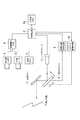
以下、本発明の実施形態を図面に基づいて説明する。図1は、本発明の一実施形態に係る移動物体報知装置の構成を示すブロック図である。同図に示すように、この移動物体報知装置は、車両前方に存在する検出対象7を撮影する赤外線カメラ3、及び可視カメラ4と、ミリ波を出射して検出対象7(例えば、歩行者)までの距離を測定するミリ波レーダ(距離計測手段)5を有し、更に、これらの出力に基づいて、検出対象7の位置を検出する位置検出手段6を備えている。
【0011】
また、この移動物体報知装置は、検出対象7に向けてレーザを発するレーザダイオード(電磁波ビーム照射手段)1と、このレーザダイオード1の出力側に配設され、出射されたレーザを水平方向、及び垂直方向に走査する二次元スキャナ(ビーム走査手段)8と、該二次元スキャナ8の走査方向を制御するスキャナ駆動手段10と、を備えている。
【0012】
更に、二次元スキャナ8の水平、及び垂直方向の走査位置を検出してデジタル信号に変換する走査位置検出手段9と、二次元スキャナ8にて走査されたレーザの照射方向が検出対象7の方向に向くようにレーザを反射させる反射ミラー11と、制御回路(照射状態可変手段)2を備えている。
【0013】
制御回路2は、位置検出手段6にて検出された検出対象7の位置情報に基づいて、レーザダイオード1によるレーザの出射を制御すると共に、後述する手順により、二次元スキャナ8による水平、垂直方向の走査指令信号をスキャナ駆動手段10に出力する。また、後述する警報パターンを記憶するための二次元メモリ2aを備えている。
【0014】
次に、上記のように構成された本実施形態に係る移動物体報知装置の作用を、図2に示すフローチャート、及び図3〜図7に示す説明図を参照しながら説明する。
【0015】
図3は、自車前方の映像を模式的に示す説明図であり、自車が走行中の自車線20の右側には、センターライン23を挟んで反対車線22が存在し、左側には路肩21が存在する。そして、歩行者(移動物体)24が自車前方約50mの距離で、路肩21から、自車線20に図中左側から右側に向けて侵入している。
【0016】
図2に示すフローチャートにおいて、位置検出手段6及び制御回路2では、以下に説明するロジックが作用する。
【0017】
まず、ステップS10において、運転者がシステムスイッチ(図示省略)をONすることにより、本システムが作動する。
【0018】
ステップS20において、赤外線カメラ3で撮影された画像を1フレーム取り込む。図4はこのときの状態を説明する図であり、歩行者24のみが、体温に感度を有することにより、強調して撮像されている。
【0019】
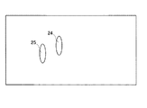
次いで、ステップS30において、ミリ波レーダ5で検出された画像を1フレーム取り込む。図5は、このときの状態を説明する図であり、物標としての歩行者24、及び街路樹25がミリ波を反射し、これら物標までの距離が計算される。本図において、歩行者24までの距離は50m、街路樹25までの距離は30mと計算されている。
【0020】
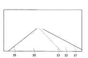
ステップS40において、可視カメラ4で撮影された画像を1フレーム取り込む。図6は、このときの状態を説明する図であり、色階調値の差によって白または黄色の線(路上の仕切線)のみが抽出され、図中左より、第1の路側線26、センターライン23、第2の路側線27が抽出される。
【0021】
更に、ステップS40においては、自車線20を特定するため、第1の路側線26、センターライン23、第2の路側線27の色階調の変化量(エッジ)を抽出し、自車線20中央の位置から左右方向に向かって近い順にエッジの座標を抽出する。すると、第1の路側線26の左右方向内側のエッジ、センターライン23の左右方向内側のエッジが抽出される。これらエッジの線分としての連続性及び直線らしさを既知のハフ変換等の数値処理を行って、連続した線分としてグルーピングを行う。上述の説明により抽出された、線分で囲まれる領域が自車線20であるものと識別する。図7に、上記の処理で識別された自車線20の領域を示す。
【0022】
ステップS50において、ステップS20の赤外線カメラ3により抽出された領域と、ステップS30の処理により抽出された領域との論理和をとり、赤外線感度があり、且つ距離情報を有するものが、歩行者24であるものと認識する。ここで、街路樹25は赤外線に感度を有さないので除外される。
【0023】
ステップS60において、歩行者24の横位置、及び距離を算出する。横位置は、ステップS20により取り込まれた赤外線カメラ3の画像の横画素値を計算し、距離はステップS30により取り込まれたミリ波レーダ5の出力情報を用いて算出する。
【0024】
ステップS70では、ステップS60にて抽出された歩行者24が、ステップS40で抽出された自車線内に存在するか否かを判別する。存在しない場合は、ステップS20に戻り、存在する場合はステップS80に進む。自車線は必要に応じて、膨張等の画像処理手段により、多少図中左右方向に拡大してもよい。
【0025】
これは歩行者24が高さ方向に領域を有しているため、厳密に、自車線を規定したとき、歩行者24の存在を示す警報出力と自車線の規定とが運転者に違和感を与える場合に有効である。ただし、膨張量を大きくしすぎると、本来問題とならない路肩21を歩行する歩行者に対しても警報を与えることになり、誤警報の原因となるため、適切な値を設定することが必要である。
【0026】
ステップS80において、歩行者24までの距離が100mより大きいか否かが判断される。100mより大きいと判断された場合には、後述の第1警報を作動し、ステップS110に進む。他方、100m以下であると判断された場合には、ステップS90の処理に進む。
【0027】
ステップS90にて、歩行者24までの距離が50m〜100mの範囲に存在するか否かが判断される。この範囲内に存在する場合には、後述する第2警報を作動してステップS110に進む。また、この範囲内に存在しない場合には、ステップS100に進む。
【0028】
ステップS100において、歩行者24までの距離が50m以下に存在するか否かが判断される。50m以下である場合には、後述する第3警報を作動して、ステップS110に進む。それ以外の場合には、エラーとしてステップS110に進む。
【0029】
ステップS110にて、システムがON、即ち作動状態にあるか否かを判断し、システムがONである場合には、ステップS20に戻り、OFFである場合には、処理を終了する。
【0030】
図8〜図10は、上述した第1警報〜第3警報を発生する際の、作用を示す説明図である。
【0031】
図2のステップS80において、歩行者が100mを超える位置に存在すると判定された場合には、第1警報の作動の分岐に入り、二次元メモリ2aに格納されている図8に示す如くのメモリパターンが選択される。
【0032】
水平方向に200個、垂直方向に100個の配列を有する二次元メモリ2aには、メモリパターンとして、予め警報の表示パターンを入力してある。図8は、第1警報に用いるメモリパターンであり、図示のように、例えば折れ曲がった矢印の点線を描いたメモリパターンとすることができる。水平方向のメモリ番地をx、垂直方向のメモリ番地をyで表記し、各メモリの番地を(x,y)で表すことにする。
【0033】
図中(80,5)から(85,45)を経由して折れ曲がり(100,60)までの破線、及び矢印の描画データが各メモリに1ビットのデータとして記録されている。
【0034】
このメモリの構造を、図11を参照して、より詳しく説明する。図11は、図8に示したメモリ配列のうち、(78,5)から(83,10)までのメモリ配列に限定して記載した図であり、丁度図8における破線の開始領域に相当する。図11は、横軸にx番地、縦軸にy番地を表しており、(x、y)の形式で記載すると、(80,5)、(80,6)、(80,8)、(81,9)、(81,10)のメモリ番地のデータが「1」でありその他の番地のデータは「0」である。
【0035】
以上のように図8においても水平方向に200個、垂直方向に100個の、合計20000個のメモリの各番地に「0」、または「1」のデータを記憶させておくことにより、任意の画像データを二次元メモリ2aに格納することが可能となっている。
【0036】
同様に、図2のステップS90において、歩行者が100m以下で、且つ50mを超える位置に存在する場合には、第2警報の作動の分岐に入り、この場合には、図9に示す如くのメモリパターンが選択される。
【0037】
図9において、メモリ番地(80,5)から(81,30)を経由して折れ曲がり、(110,50)までの破線および矢印の描画データが各メモリに1ビットのデータとして記録されている。
【0038】
同様に、ステップS100において、歩行者が50m以下の位置に存在する場合には、第3警報の作動の分岐に入り、図10のメモリパターンが選択される。
【0039】
図10は、第3警報に用いるメモリ記憶パターンであり、図中(80,5)から(82,20)を経由して折れ曲がり、(110,40)までの破線及び矢印の描画データが各メモリに1ビットのデータとして記録されている。
【0040】
走査位置検出回路9の出力信号により、現在のレーザ照射方向が水平方向200個、垂直方向100個の各メモリ番地のいずれの位置に存在するかを、常時二次元の位置データとして検出しており、逐次対応する番地のメモリ値を読み出す。
【0041】
もし、メモリ値が「1」の場合、制御回路2はレーザダイオード1に発光指令を出力する。また、メモリ値が「0」の場合は逆に発光指令を送出しない。
【0042】
以上の操作を、メモリ番地における水平方向200個、垂直方向100個のデータに対応する前方へのレーザレーダのビーム照射を断続させることにより、メモリパターンに等しいパターンのレーザビームがマーカとして自車前方に照射され、その結果、運転者は自車前方の路面にメモリパターンと等しいマーカを認知することが可能となる。従って、記号情報による強調された報知により、運転者は移動物体の存在を直ちに認識することができる。
【0043】
図12は、第2警報が報知された状態の前方風景を示しており、歩行者24を回避するようにマーカ28が路面に照射されている。また、本実施例の変形例としてステップS60において、歩行者24が自車走行車線の左、または右のいづれに位置するかに応じて、警報のメモリパターンを変更してもよい。
【0044】
例えば、図8〜図10に示した、警報のメモリパターンは、自車線の左側に歩行者24が位置する状況に適切なメモリーパターンを用いて説明している。歩行者24は主として自車線左側に位置するときがリスク度が高いため、効果的な報知方法であるが、まれに、自車線の右に歩行者24が位置する場合もある。
【0045】
この場合、ステップS60で歩行者の横位置情報に従い、歩行者が自車線の右に位置する場合は図13に示すように、自車の進行を左側に迂回するようレーザダイオードにより路面にマーカ28を描画してもよいし、停止記号を描画してもよい。
【0046】
なお、本実施形態においては、第1警報から第3警報までの3段階に警報の緊急度を可変とする構成に基づいて説明しているが、必要に応じて、任意の警報の段階に定めてもよい。
【0047】
また、本実施形態においては、1つのレーザダイオード1によりレーザビームを照射する構成において説明しているが、請求項2に記載したマーカの照射パターンを変化させる一例として、RGB3色のレーザダイオードを用いて、各ダイオードの発光出力を制御することにより、マーカ28の色を可変にすることや、レーザダイオード1の照射間隔を可変にすることにより、マーカ28を点滅させるようにすることも可能である。このような構成によれば、運転者による情報認知を容易とすることができる。
【0048】
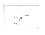
また、請求項3に記載したように、位置検出手段6の信号に基づき、歩行者24までの距離が既知であることを利用して、図14に示すように、歩行者24までの距離より5m手前側の位置に注意マーカ29を呈示することも可能である。このような構成によれば、電磁波ビームの人体への照射を防止することが可能となり、その結果、人が急に光を照射されることにより驚き、その場に立ち止まってしまうという状況が発生することを防止することができる。
【0049】
また、マーカが、自車両を迂回誘導する走路情報として表示されるので、運転者が直ちにどのように回避動作を行えばよいかを直感的に判断することができ、その結果、回避動作を素速く行うことができる。
【0050】
また、請求項1に記載したように、距離情報に依存せずに、自車前方視野角の垂直方向に関して、上は遠方、下は近距離であるという、擬似的な距離検出論理に基づいて、本実施形態にて説明した作用を具現化することも、コスト低減の観点から効果的である。
【0051】
更に、請求項5に記載したように、反対車線22に車両が存在する場合、即ち、赤外線カメラ3により検出された対向車のヘッドライトの間隔と、ミリ波レーダ5にて検出された、対向車までの距離に応じて演算される、車両か否かの判定により、対向車線22に存在する物体が対向車であると制御回路2により認識された場合には、図15に示すように、照射制限領域30を、対向車を検出した領域の略同一部位に設定し、本照射制限領域30で歩行者24を検出した場合は、請求項3に記載したように、歩行者24の前方5mの位置に、マーカ28を照射するようにすれば、対向車に与える幻惑を防止できる。
【0052】
以上、各実施形態は、更に、自車の走行速度に応じて、マーカ28の描画を制御することも可能である。例えば、車速が高いときは、照射領域を遠方に設定する、照射光量を増大する、照射の色をよりリスク度が高いことを示す色、例えば黄色や赤スペクトル成分を増大する、照射間隔を短めに設定する等の制御である。
【0053】
同様に、周囲の光量が低い、例えば、夜間の場合、夕暮れ時、及び昼間と制御量を可変にする、また、雨、霧、雪等の場合もこれら各種制御量を可変にするといった制御を付加してもよい。
【0054】
また、上記各実施形態は、検出対象7を人間として説明しているが、自転車、バイク、車両に適用してもよい。
【0055】
更に、上記各実施形態は、熱物体を検出する赤外線カメラ3、距離を検出するミリ波レーダ5、白線等の道路仕切線を検出する可視カメラ4を用いた構成に基づき説明したが、自車線を特定せずに、自車前方の熱物体を検出し、警報を行うならば、可視カメラ4は不要である。
【0056】
また、熱物体(人体)までの距離を正確に測定する必要がない場合は、赤外線カメラ3の上下方向の画素値から算出される、距離対応情報により、簡易的に熱物体までの距離を測定しても良い。また、熱に特化せずに、人体等の障害物を検出するには、赤外線カメラ3に限定されるものではなく、近赤外領域に感度を有する、可視カメラ4、レーザレーダ、超音波、電磁波による障害物検出手段で代用してもよい。
【図面の簡単な説明】
【図1】本発明の一実施形態に係る移動物体報知装置の構成を示すブロック図である。
【図2】本発明の一実施形態に係る移動物体報知装置の処理手順を示すフローチャートである。
【図3】自車前方の映像を示す説明図である。
【図4】自車両前方に存在する熱物体(歩行者)の映像を示す説明図である。
【図5】ミリ波レーダにより検出される自車前方障害物の映像を示す説明図である。
【図6】自車前方に存在する自車線、及び対向車線の映像を示す説明図である。
【図7】自車前方に存在する自車線の映像を示す説明図である。
【図8】二次元メモリに記憶される第1警報の表示パターンを示す説明図である。
【図9】二次元メモリに記憶される第2警報の表示パターンを示す説明図である。
【図10】二次元メモリに記憶される第3警報の表示パターンを示す説明図である。
【図11】メモリに記憶されるビットパターンを示す説明図である。
【図12】第1警報の表示パターンを、レーザダイオードを用いて自車前方に表示するマーカの例を示す説明図であり、歩行者が左側から自車線内に進入した場合の表示例である。
【図13】第1警報の表示パターンを、レーザダイオードを用いて自車前方に表示するマーカの例を示す説明図であり、歩行者が右側から自車線内に進入した場合の表示例である。
【図14】マーキングの対象となる歩行者の手前に注意マーカを照射した場合の例を示す説明図である。
【図15】対向車が存在する場合に設定される照射制限領域を示す説明図である。
【符号の説明】
1 レーザダイオード
2 制御回路
3 赤外線カメラ
4 可視カメラ
5 ミリ波レーダ
6 位置検出手段
7 検出対象
8 二次元スキャナ
9 走査位置検出回路
10 スキャナ駆動手段
11 反射ミラー
20 自車線
21 路肩
22 反対車線
23 センターライン
24 歩行者
25 街路樹
26 第1の路側線
27 第2の路側線
28 マーカ
29 注意マーカ
30 照射制限領域[0001]
TECHNICAL FIELD OF THE INVENTION
The present invention relates to a moving object notifying device that detects a moving object such as a pedestrian existing in front of a host vehicle at night, at dusk, or when the surroundings are dark, such as a pedestrian, and notifies the occupant of the vehicle of the detection. .
[0002]
[Prior art]
2. Description of the Related Art Conventionally, as a technique for following a moving object, for example, a moving body following spotlight control device disclosed in Japanese Patent Application Laid-Open No. 2002-83383 (Patent Document 1) and a method for detecting and controlling the moving body have been known. The invention disclosed in
[0003]
[Patent Document 1]
JP-A-2002-83383
[Problems to be solved by the invention]
However, as described in
[0005]
(B) Since the driver needs to constantly perform various confirmation actions such as rearward, lateral and in-vehicle, as well as monitoring the condition of the road ahead, simply irradiating a spotlight on a moving object such as a human body, The driver may not notice.
(B) Since many checks and operations are performed at the same time while the vehicle is driving, it takes time to think about what kind of evasion operation to perform immediately even if the moving object is simply informed to the driver. That is, after confirming the moving object, whether there is a space for avoiding the own vehicle around this moving object, whether there is a deceleration, or whether or not it can be avoided only by operating the steering wheel, If there is no space to avoid the car, it is necessary to determine whether to stop or to decelerate and pass immediately.
[0006]
(C) When a moving object such as a human body exists near the oncoming vehicle, the spotlight is irradiated not only on the human body but also on the oncoming vehicle, which may cause dazzling for the driver of the oncoming vehicle.
[0007]
The present invention has been made to solve such a conventional problem, and an object of the present invention is to detect a moving object existing in front of a vehicle and accurately determine an action to be taken by a driver after the detection. The object of the present invention is to provide a moving object notification device capable of giving an instruction to a moving object.
[0008]
[Means for Solving the Problems]
In order to achieve the above object, the present invention relates to a moving object notification device that detects a moving object existing in front of a vehicle and notifies the occupant of the vehicle of the moving object. Moving object detecting means for detecting the moving object to be a target, position detecting means for detecting the position of the moving object based on the detection result of the moving object detecting means, and detecting the position of the moving object by the position detecting means. An irradiation state changing unit that changes an irradiation pattern by the marker irradiation unit in accordance with a position of a moving object, wherein the marker irradiation unit emits an electromagnetic wave beam and emits an electromagnetic wave beam in front of the vehicle. A beam scanning unit that scans within a predetermined area of the electronic device, wherein the irradiation state changing unit is configured to control the electromagnetic irradiation according to a scanning position of the beam scanning unit. Adjust the electromagnetic beam emitted from the beam irradiation unit, and generating an arbitrary marker in the predetermined area.
[0009]
【The invention's effect】
According to the present invention, when a moving object is present in front of the vehicle, information for avoiding approach to the moving object is displayed as a marker in a predetermined area in front of the vehicle, so that the driver himself It is possible to immediately recognize the action to be taken and to support appropriate action determination in an emergency.
[0010]
BEST MODE FOR CARRYING OUT THE INVENTION
Hereinafter, embodiments of the present invention will be described with reference to the drawings. FIG. 1 is a block diagram illustrating a configuration of a moving object notification device according to an embodiment of the present invention. As shown in the figure, the moving object notification device includes an infrared camera 3 and a
[0011]
The moving object notification device also includes a laser diode (electromagnetic wave beam irradiation means) 1 for emitting a laser beam toward a
[0012]
Further, scanning position detecting means 9 for detecting the horizontal and vertical scanning positions of the two-dimensional scanner 8 and converting them into digital signals, and the irradiation direction of the laser scanned by the two-dimensional scanner 8 is the direction of the
[0013]
The
[0014]
Next, the operation of the moving object notification device according to the present embodiment configured as described above will be described with reference to the flowchart shown in FIG. 2 and the explanatory diagrams shown in FIGS.
[0015]
FIG. 3 is an explanatory diagram schematically showing an image in front of the own vehicle. An
[0016]
In the flowchart shown in FIG. 2, the logic described below operates in the position detecting means 6 and the
[0017]
First, in step S10, when the driver turns on a system switch (not shown), the present system operates.
[0018]
In step S20, an image captured by the infrared camera 3 is captured in one frame. FIG. 4 is a diagram for explaining the state at this time, and only the
[0019]
Next, in step S30, one frame of the image detected by the millimeter wave radar 5 is captured. FIG. 5 is a diagram for explaining the state at this time. The
[0020]
In step S40, an image captured by the
[0021]
Further, in step S40, in order to identify the
[0022]
In step S50, a logical sum of the area extracted by the infrared camera 3 in step S20 and the area extracted by the processing in step S30 is taken, and the one having infrared sensitivity and having the distance information is the
[0023]
In step S60, the lateral position and the distance of the
[0024]
In step S70, it is determined whether the
[0025]
This is because the
[0026]
In step S80, it is determined whether the distance to the
[0027]
In step S90, it is determined whether the distance to
[0028]
In step S100, it is determined whether the distance to the
[0029]
In step S110, it is determined whether or not the system is ON, that is, in an operating state. If the system is ON, the process returns to step S20, and if it is OFF, the process ends.
[0030]
FIG. 8 to FIG. 10 are explanatory diagrams showing the operation when the above-described first to third alarms are generated.
[0031]
When it is determined in step S80 in FIG. 2 that the pedestrian is present at a position exceeding 100 m, the operation of the first alarm is started, and the memory stored in the two-
[0032]
In the two-
[0033]
In the figure, drawing data of a broken line and an arrow from (80, 5) to bend (100, 60) via (85, 45) are recorded as 1-bit data in each memory.
[0034]
The structure of this memory will be described in more detail with reference to FIG. FIG. 11 is a diagram showing only the memory arrays (78, 5) to (83, 10) in the memory array shown in FIG. 8, and corresponds to the start area indicated by the broken line in FIG. . FIG. 11 shows the address x on the horizontal axis and the address y on the vertical axis. When described in the form of (x, y), (80, 5), (80, 6), (80, 8), (80) The data at the memory addresses 81, 9) and (81, 10) is "1", and the data at the other addresses are "0".
[0035]
As described above, in FIG. 8 as well, by storing data of “0” or “1” at each address of a total of 20,000 memories, 200 in the horizontal direction and 100 in the vertical direction, Image data can be stored in the two-
[0036]
Similarly, in step S90 of FIG. 2, when the pedestrian is at a position of 100 m or less and more than 50 m, the operation enters the branch of the operation of the second alarm, and in this case, as shown in FIG. The memory pattern is selected.
[0037]
In FIG. 9, the data is bent from the memory address (80, 5) via (81, 30), and the drawing data of the broken line and the arrow from (110, 50) is recorded as 1-bit data in each memory.
[0038]
Similarly, in step S100, if the pedestrian is present at a position of 50 m or less, the process enters the third alarm operation branch, and the memory pattern in FIG. 10 is selected.
[0039]
FIG. 10 shows a memory storage pattern used for the third alarm. In FIG. 10, the drawing data is bent from (80, 5) to (82, 20), and the drawing data of a broken line and an arrow from (110, 40) is stored in each memory. Is recorded as 1-bit data.
[0040]
The output signal of the scanning
[0041]
If the memory value is “1”, the
[0042]
By performing the above operation by intermittently irradiating the laser beam forward of the laser radar corresponding to 200 horizontal and 100 vertical data at the memory address, a laser beam having a pattern equal to the memory pattern is used as a marker in front of the own vehicle. As a result, the driver can recognize a marker equal to the memory pattern on the road surface ahead of the own vehicle. Therefore, the driver can immediately recognize the presence of the moving object by the emphasized notification by the symbol information.
[0043]
FIG. 12 shows a scene in front of the vehicle in a state where the second alarm is notified, and the
[0044]
For example, the alarm memory patterns shown in FIGS. 8 to 10 are described using a memory pattern appropriate for a situation where the
[0045]
In this case, according to the lateral position information of the pedestrian in step S60, when the pedestrian is located on the right side of the own lane, as shown in FIG. May be drawn, or a stop symbol may be drawn.
[0046]
Although the present embodiment has been described based on a configuration in which the degree of urgency of an alarm is variable in three stages from a first alarm to a third alarm, an arbitrary alarm stage may be set as necessary. You may.
[0047]
Further, in the present embodiment, a configuration in which a laser beam is irradiated by one
[0048]
Further, as described in claim 3, by utilizing the fact that the distance to the
[0049]
In addition, since the marker is displayed as information on the traveling route that guides the vehicle around the host vehicle, it is possible to intuitively determine how the driver should immediately perform the avoidance operation. Can be done fast.
[0050]
In addition, as described in
[0051]
Further, as described in claim 5, when a vehicle is present in the
[0052]
As described above, in each embodiment, it is also possible to control the drawing of the
[0053]
Similarly, when the amount of light in the surroundings is low, for example, in the case of night, at dusk, and in the daytime, the control amount is made variable, and in the case of rain, fog, snow, and the like, these various control amounts are made variable. It may be added.
[0054]
In the above embodiments, the
[0055]
Furthermore, each of the above embodiments has been described based on the configuration using the infrared camera 3 for detecting a thermal object, the millimeter wave radar 5 for detecting a distance, and the
[0056]
When it is not necessary to accurately measure the distance to the thermal object (human body), the distance to the thermal object is simply measured by distance correspondence information calculated from the pixel values of the infrared camera 3 in the vertical direction. You may. Further, the detection of an obstacle such as a human body without specializing in heat is not limited to the infrared camera 3, but a
[Brief description of the drawings]
FIG. 1 is a block diagram illustrating a configuration of a moving object notification device according to an embodiment of the present invention.
FIG. 2 is a flowchart illustrating a processing procedure of the moving object notification device according to the embodiment of the present invention.
FIG. 3 is an explanatory diagram showing an image in front of a host vehicle.
FIG. 4 is an explanatory diagram showing an image of a thermal object (pedestrian) existing in front of the host vehicle.
FIG. 5 is an explanatory diagram showing an image of an obstacle ahead of the vehicle detected by the millimeter wave radar.
FIG. 6 is an explanatory diagram showing images of an own lane and an oncoming lane existing in front of the own vehicle.
FIG. 7 is an explanatory diagram showing an image of an own lane existing ahead of the own vehicle.
FIG. 8 is an explanatory diagram showing a display pattern of a first alarm stored in a two-dimensional memory.
FIG. 9 is an explanatory diagram showing a display pattern of a second alarm stored in a two-dimensional memory.
FIG. 10 is an explanatory diagram showing a display pattern of a third alarm stored in a two-dimensional memory.
FIG. 11 is an explanatory diagram showing bit patterns stored in a memory.
FIG. 12 is an explanatory diagram illustrating an example of a marker that displays a display pattern of a first warning in front of the own vehicle using a laser diode, and is a display example when a pedestrian enters the own lane from the left side. .
FIG. 13 is an explanatory diagram showing an example of a marker for displaying a display pattern of a first warning in front of the own vehicle using a laser diode, and is a display example when a pedestrian enters the own lane from the right side. .
FIG. 14 is an explanatory diagram illustrating an example of a case where a caution marker is irradiated in front of a pedestrian to be marked;
FIG. 15 is an explanatory diagram showing an irradiation restriction area set when an oncoming vehicle is present.
[Explanation of symbols]
DESCRIPTION OF
Claims (5)
車両前方にマーカを照射するマーカ照射手段と、
マーキングの対象となる前記移動物体を検出する移動物体検出手段と、
前記移動物体検出手段の検出結果に基づいて、前記移動物体の位置を検出する位置検出手段と、
前記位置検出手段により検出された前記移動物体の位置に応じて、前記マーカ照射手段による照射パターンを変化させる照射状態可変手段と、を有し、
前記マーカ照射手段は、電磁波ビームを照射する電磁波ビーム照射手段、及び電磁波ビームを車両前方の所定の領域内にて走査するビーム走査手段を備え、
前記照射状態可変手段は、前記ビーム走査手段の走査位置に応じて、前記電磁波ビーム照射手段より照射する電磁波ビームを調整して、前記所定の領域内に任意のマーカを生成することを特徴とする移動物体報知装置。In a moving object notification device that detects a moving object existing in front of the vehicle and notifies the occupant of the vehicle of this detection,
Marker irradiating means for irradiating the marker in front of the vehicle,
Moving object detecting means for detecting the moving object to be marked,
Position detection means for detecting the position of the moving object based on the detection result of the moving object detection means,
An irradiation state changing unit that changes an irradiation pattern by the marker irradiation unit according to the position of the moving object detected by the position detection unit,
The marker irradiating unit includes an electromagnetic wave beam irradiating unit that irradiates an electromagnetic wave beam, and a beam scanning unit that scans the electromagnetic wave beam in a predetermined area in front of the vehicle,
The irradiation state changing unit adjusts an electromagnetic wave beam irradiated from the electromagnetic wave beam irradiation unit according to a scanning position of the beam scanning unit, and generates an arbitrary marker in the predetermined area. Moving object notification device.
前記照射状態可変手段は、前記距離計測手段の計測結果に基づいて、マーカの照射パターンを変化させることを特徴とする請求項1に記載の移動物体報知装置。Providing distance measuring means for measuring the distance from the vehicle to the moving object, the position detecting means, based on the distance to the moving object measured by the distance measuring means, detects the position of the moving object,
The moving object notification device according to claim 1, wherein the irradiation state changing unit changes an irradiation pattern of the marker based on a measurement result of the distance measurement unit.
Priority Applications (1)
| Application Number | Priority Date | Filing Date | Title |
|---|---|---|---|
| JP2003152453A JP3823944B2 (en) | 2003-05-29 | 2003-05-29 | Moving object notification device |
Applications Claiming Priority (1)
| Application Number | Priority Date | Filing Date | Title |
|---|---|---|---|
| JP2003152453A JP3823944B2 (en) | 2003-05-29 | 2003-05-29 | Moving object notification device |
Publications (2)
| Publication Number | Publication Date |
|---|---|
| JP2004355341A true JP2004355341A (en) | 2004-12-16 |
| JP3823944B2 JP3823944B2 (en) | 2006-09-20 |
Family
ID=34047670
Family Applications (1)
| Application Number | Title | Priority Date | Filing Date |
|---|---|---|---|
| JP2003152453A Expired - Fee Related JP3823944B2 (en) | 2003-05-29 | 2003-05-29 | Moving object notification device |
Country Status (1)
| Country | Link |
|---|---|
| JP (1) | JP3823944B2 (en) |
Cited By (4)
| Publication number | Priority date | Publication date | Assignee | Title |
|---|---|---|---|---|
| JP2006252264A (en) * | 2005-03-11 | 2006-09-21 | Omron Corp | Obstacle informing device |
| JP2008143510A (en) * | 2006-11-17 | 2008-06-26 | Toyota Central R&D Labs Inc | Warning irradiation device |
| CN114639230A (en) * | 2020-12-15 | 2022-06-17 | 丰田自动车株式会社 | Walking assistance system |
| WO2024024577A1 (en) * | 2022-07-25 | 2024-02-01 | スタンレー電気株式会社 | Vehicle light distribution system and vehicle light distribution method |
Citations (4)
| Publication number | Priority date | Publication date | Assignee | Title |
|---|---|---|---|---|
| JPH05238307A (en) * | 1992-02-26 | 1993-09-17 | Yukitaka Nakazato | Front view device for vehicle |
| JPH1096776A (en) * | 1996-09-24 | 1998-04-14 | Honda Access Corp | Display device for inter vehicle distance |
| WO2002038416A1 (en) * | 2000-11-09 | 2002-05-16 | Astron Group Technologies S.A. | Visual signalling device adaptable to a vehicle |
| JP2003231450A (en) * | 2002-02-07 | 2003-08-19 | Toyota Motor Corp | Mobile device safety device |
-
2003
- 2003-05-29 JP JP2003152453A patent/JP3823944B2/en not_active Expired - Fee Related
Patent Citations (4)
| Publication number | Priority date | Publication date | Assignee | Title |
|---|---|---|---|---|
| JPH05238307A (en) * | 1992-02-26 | 1993-09-17 | Yukitaka Nakazato | Front view device for vehicle |
| JPH1096776A (en) * | 1996-09-24 | 1998-04-14 | Honda Access Corp | Display device for inter vehicle distance |
| WO2002038416A1 (en) * | 2000-11-09 | 2002-05-16 | Astron Group Technologies S.A. | Visual signalling device adaptable to a vehicle |
| JP2003231450A (en) * | 2002-02-07 | 2003-08-19 | Toyota Motor Corp | Mobile device safety device |
Cited By (5)
| Publication number | Priority date | Publication date | Assignee | Title |
|---|---|---|---|---|
| JP2006252264A (en) * | 2005-03-11 | 2006-09-21 | Omron Corp | Obstacle informing device |
| JP2008143510A (en) * | 2006-11-17 | 2008-06-26 | Toyota Central R&D Labs Inc | Warning irradiation device |
| CN114639230A (en) * | 2020-12-15 | 2022-06-17 | 丰田自动车株式会社 | Walking assistance system |
| CN114639230B (en) * | 2020-12-15 | 2024-01-30 | 丰田自动车株式会社 | Walking assistance system |
| WO2024024577A1 (en) * | 2022-07-25 | 2024-02-01 | スタンレー電気株式会社 | Vehicle light distribution system and vehicle light distribution method |
Also Published As
| Publication number | Publication date |
|---|---|
| JP3823944B2 (en) | 2006-09-20 |
Similar Documents
| Publication | Publication Date | Title |
|---|---|---|
| US6727807B2 (en) | Driver's aid using image processing | |
| CN102779430B (en) | Collision-warning system, controller and method of operating thereof after the night of view-based access control model | |
| JP6075331B2 (en) | Vehicle lighting device | |
| JP6471528B2 (en) | Object recognition apparatus and object recognition method | |
| JP5680573B2 (en) | Vehicle driving environment recognition device | |
| JP5761002B2 (en) | Lighting control device | |
| JP6557843B1 (en) | VEHICLE CONTROL DEVICE, CONTROL SYSTEM, AND CONTROL PROGRAM | |
| US20060151223A1 (en) | Device and method for improving visibility in a motor vehicle | |
| RU2724935C1 (en) | METHOD AND SYSTEM OF NOTIFICATION OF A LOAD CAR DRIVER | |
| JP3123303B2 (en) | Vehicle image processing device | |
| US9784839B2 (en) | Automotive lighting device and a vehicle having the same | |
| CN108859959A (en) | Vehicle environmental imaging system and method | |
| JP2000339589A (en) | Vehicle traffic safety assistance system and recording medium | |
| JP2017159699A (en) | Vehicle lighting device | |
| JP4415856B2 (en) | Method for detecting the forward perimeter of a road vehicle by a perimeter sensing system | |
| JP2004514384A (en) | Method and apparatus for monitoring the surroundings of a vehicle | |
| JP4063142B2 (en) | Obstacle notification device at night | |
| US20190322210A1 (en) | Apparatus and method for notifying expected motion of vehicle | |
| JP2004185105A (en) | Obstacle notification device | |
| JP2006185410A (en) | Night moving object notification device and night moving object notification method | |
| JP2008098976A (en) | Solid-state image sensor | |
| JP2006176020A (en) | Pedestrian notification device and method | |
| KR101104833B1 (en) | Safe operation information providing device and safe operation information providing method | |
| JP3822417B2 (en) | Vehicle periphery monitoring device | |
| JP2018163530A (en) | Object detection device, object detection method, and object detection program |
Legal Events
| Date | Code | Title | Description |
|---|---|---|---|
| A131 | Notification of reasons for refusal |
Free format text: JAPANESE INTERMEDIATE CODE: A131 Effective date: 20060314 |
|
| A521 | Written amendment |
Free format text: JAPANESE INTERMEDIATE CODE: A523 Effective date: 20060421 |
|
| TRDD | Decision of grant or rejection written | ||
| A01 | Written decision to grant a patent or to grant a registration (utility model) |
Free format text: JAPANESE INTERMEDIATE CODE: A01 Effective date: 20060606 |
|
| A61 | First payment of annual fees (during grant procedure) |
Free format text: JAPANESE INTERMEDIATE CODE: A61 Effective date: 20060619 |
|
| R150 | Certificate of patent or registration of utility model |
Free format text: JAPANESE INTERMEDIATE CODE: R150 |
|
| LAPS | Cancellation because of no payment of annual fees |