JP2004361401A - Optoelectronic rotation angle sensor - Google Patents
Optoelectronic rotation angle sensor Download PDFInfo
- Publication number
- JP2004361401A JP2004361401A JP2004162719A JP2004162719A JP2004361401A JP 2004361401 A JP2004361401 A JP 2004361401A JP 2004162719 A JP2004162719 A JP 2004162719A JP 2004162719 A JP2004162719 A JP 2004162719A JP 2004361401 A JP2004361401 A JP 2004361401A
- Authority
- JP
- Japan
- Prior art keywords
- rotation angle
- angle sensor
- light
- optoelectronic
- code disk
- Prior art date
- Legal status (The legal status is an assumption and is not a legal conclusion. Google has not performed a legal analysis and makes no representation as to the accuracy of the status listed.)
- Pending
Links
- 230000005693 optoelectronics Effects 0.000 title claims abstract description 27
- 230000008878 coupling Effects 0.000 claims abstract description 15
- 238000010168 coupling process Methods 0.000 claims abstract description 15
- 238000005859 coupling reaction Methods 0.000 claims abstract description 15
- 230000003287 optical effect Effects 0.000 claims abstract description 9
- 230000002093 peripheral effect Effects 0.000 claims description 2
- 230000004907 flux Effects 0.000 description 2
- 239000000463 material Substances 0.000 description 2
- VVQNEPGJFQJSBK-UHFFFAOYSA-N Methyl methacrylate Chemical compound COC(=O)C(C)=C VVQNEPGJFQJSBK-UHFFFAOYSA-N 0.000 description 1
- 229920005372 Plexiglas® Polymers 0.000 description 1
- 230000001419 dependent effect Effects 0.000 description 1
- 230000000694 effects Effects 0.000 description 1
- 238000000034 method Methods 0.000 description 1
- 238000007645 offset printing Methods 0.000 description 1
- 239000003973 paint Substances 0.000 description 1
- 230000005855 radiation Effects 0.000 description 1
- 230000035945 sensitivity Effects 0.000 description 1
Images
Classifications
-
- G—PHYSICS
- G01—MEASURING; TESTING
- G01D—MEASURING NOT SPECIALLY ADAPTED FOR A SPECIFIC VARIABLE; ARRANGEMENTS FOR MEASURING TWO OR MORE VARIABLES NOT COVERED IN A SINGLE OTHER SUBCLASS; TARIFF METERING APPARATUS; MEASURING OR TESTING NOT OTHERWISE PROVIDED FOR
- G01D5/00—Mechanical means for transferring the output of a sensing member; Means for converting the output of a sensing member to another variable where the form or nature of the sensing member does not constrain the means for converting; Transducers not specially adapted for a specific variable
- G01D5/26—Mechanical means for transferring the output of a sensing member; Means for converting the output of a sensing member to another variable where the form or nature of the sensing member does not constrain the means for converting; Transducers not specially adapted for a specific variable characterised by optical transfer means, i.e. using infrared, visible, or ultraviolet light
- G01D5/32—Mechanical means for transferring the output of a sensing member; Means for converting the output of a sensing member to another variable where the form or nature of the sensing member does not constrain the means for converting; Transducers not specially adapted for a specific variable characterised by optical transfer means, i.e. using infrared, visible, or ultraviolet light with attenuation or whole or partial obturation of beams of light
- G01D5/34—Mechanical means for transferring the output of a sensing member; Means for converting the output of a sensing member to another variable where the form or nature of the sensing member does not constrain the means for converting; Transducers not specially adapted for a specific variable characterised by optical transfer means, i.e. using infrared, visible, or ultraviolet light with attenuation or whole or partial obturation of beams of light the beams of light being detected by photocells
- G01D5/347—Mechanical means for transferring the output of a sensing member; Means for converting the output of a sensing member to another variable where the form or nature of the sensing member does not constrain the means for converting; Transducers not specially adapted for a specific variable characterised by optical transfer means, i.e. using infrared, visible, or ultraviolet light with attenuation or whole or partial obturation of beams of light the beams of light being detected by photocells using displacement encoding scales
- G01D5/34707—Scales; Discs, e.g. fixation, fabrication, compensation
- G01D5/34715—Scale reading or illumination devices
- G01D5/34723—Scale reading or illumination devices involving light-guides
Landscapes
- Physics & Mathematics (AREA)
- General Physics & Mathematics (AREA)
- Optical Transform (AREA)
- Length Measuring Devices By Optical Means (AREA)
- Steering Controls (AREA)
Abstract
Description
本発明は、特に車輛のステアリングシステムの舵角を検出するためのオプトエレクトロニック回転角センサであって、光源、感光受信器、及び回転角を検出しなければならない構成要素に連結できるコードディスクを含む、オプトエレクトロニック回転角センサに関する。コードディスクは、光源の光に対して少なくとも部分的に透明であり、オプティカルコードが設けられている。 The invention particularly relates to an optoelectronic rotational angle sensor for detecting the steering angle of a vehicle steering system, comprising a light source, a photosensitive receiver and a code disk which can be connected to the components whose rotational angle has to be detected. , An optoelectronic rotation angle sensor. The code disk is at least partially transparent to the light of the light source and is provided with an optical code.
回転角センサは、例えば、車輛、特に自動車のハンドルの角度位置決めを決定するために使用される。従って、このようなセンサは、舵角センサとも呼ばれる。駆動−動力学制御システムを備えた車輛は、ブレーキや車輛エンジン等の特定の車輛構成要素に作用するアクチュエータを制御するための他のパラメータの他に舵角を必要とする。 Rotation angle sensors are used, for example, to determine the angular positioning of the steering wheel of a vehicle, especially a motor vehicle. Therefore, such a sensor is also called a steering angle sensor. Vehicles with a drive-dynamic control system require a steering angle in addition to other parameters for controlling actuators acting on specific vehicle components such as brakes and vehicle engines.
車輛のハンドルの回転移動と関連したコードディスクを備えたオプトエレクトロニック回転角センサが周知である。例えば、このセンサでは、コードディスクにはオプティカルコードが設けられ、光源が設けられ、この光源の光線は、コードを照射するため、光を通す本体(light−conducting body)内で偏向され、コードディスクに向けられる。コードディスクの材料は、使用された波長と対応する光源の放射線に対して少なくとも部分的に透明である。コードディスク及びコードを通る光線を受け取るため、感光受信器を使用する。好ましくは、光源、受信器、及び光を通す本体は、共通の担体上に配置される。このようなオプトエレクトロニック回転角センサは、下記特許文献1即ちドイツ国特許公開第100 36 769 A1号に記載されている。
Opto-electronic angle-of-rotation sensors with a code disk associated with the rotational movement of a vehicle steering wheel are well known. For example, in this sensor, the code disk is provided with an optical code and a light source is provided, and the light beam of this light source is deflected in a light-conducting body to illuminate the code, Turned to The material of the code disk is at least partially transparent to the radiation of the light source corresponding to the wavelength used. A photosensitive receiver is used to receive the light passing through the code disk and the code. Preferably, the light source, the receiver and the light-transmitting body are arranged on a common carrier. Such an optoelectronic rotation angle sensor is described in
光線をコード及び感光受信器に偏向するために光を通す本体を使用することにより、センサ全体の寸法が、コードディスク、光源、及び受信器で実際に必要な空間に加え、少なくとも高さに関して望ましからぬものとなる。これは、光線がコードディスクを軸線方向に横切るためである。従って、光を通す本体用の対応する空間を、コードディスクの受信器が設けられた側部とは逆の側部に設けなければならない。
本発明の目的は、空間についての必要条件が小さく、センサ構成要素の組み立てが簡単なオプトエレクトロニック回転角センサを開発することである。 It is an object of the present invention to develop an optoelectronic rotation angle sensor with small space requirements and simple assembly of the sensor components.
本発明によれば、この目的は、コードディスクが、カップリング面を含む光ガイドを構成し、光源の光がカップリング面を通ってコードディスクに進入し、感光受信器へ光を偏向する少なくとも一つの偏向面を有する、ことにより解決される。回転角センサのこの構造により、別体の構成要素である光を通す本体を省略でき、コードディスクの周面をカップリング面として使用できるため、高さに関するセンサの寸法を減少する。 According to the invention, the object is that at least the code disk constitutes a light guide comprising a coupling surface, wherein at least light from a light source enters the code disk through the coupling surface and deflects the light to a photosensitive receiver. The problem is solved by having one deflection surface. With this structure of the rotation angle sensor, it is possible to omit the light transmitting body which is a separate component, and to use the peripheral surface of the code disk as a coupling surface, thereby reducing the size of the height sensor.
光源として、例えばLEDが使用される。この光源の光線は横方向にコードディスクにカップリング面を通って半径方向に進入する。カップリング面は、本発明の一実施例では、末広がりの光線を整合して実質的に平行にするレンズを構成する。これは、コードディスク内を更に通過することを考えてのことである。このような光束がコードディスクの偏向面に当たったとき、光束の少なくとも部分が軸線方向に偏向され、コードディスクを出る。これにより、この箇所に存在するコード部分を照光する。次いで、プリント回路基板に取り付けられた少なくとも一つの感光受信器に当たる。 As the light source, for example, an LED is used. The light rays of this light source enter the code disk radially laterally through the coupling surface. The coupling surface, in one embodiment of the invention, constitutes a lens that aligns the divergent rays and makes them substantially parallel. This is in consideration of further passage through the code disk. When such a light beam strikes the deflection surface of the code disk, at least a portion of the light beam is deflected axially and exits the code disk. This illuminates the code portion present at this location. Then, it hits at least one photosensitive receiver attached to the printed circuit board.
本発明の好ましい実施例では、様々な寸法を持つフォトトランジスタが受信器として使用される。小型のフォトトランジスタは、コードディスクに面する側部に取り付けることができ、大型のフォトトランジスタは、コードディスクに向いた側部とは反対側の側部に取り付けられる。この領域では、プリント回路基板に開口部が設けられており、この開口部を通して、偏向された光の部分が、コードディスクに向いた側部とは反対側のプリント回路基板の側部に取り付けられたフォトトランジスタに当たる。開口部は、光線をこの開口部に通過させるためのダイアフラム(絞り作用板)として作用する。この効果は、開口部の大きさの影響を受ける。コード化された情報を評価するため、全ての受信器の信号を使用する。このようにして、センサの精度を向上させることができる。更に、プリント回路基板は、光源用の担体としても役立つ。 In a preferred embodiment of the invention, phototransistors of various dimensions are used as receivers. Small phototransistors can be mounted on the side facing the code disk, and large phototransistors can be mounted on the side opposite the side facing the code disk. In this area, the printed circuit board is provided with an opening through which the deflected light portion is attached to the side of the printed circuit board opposite the side facing the code disk. Photo transistor. The aperture acts as a diaphragm (aperture plate) for passing light rays through the aperture. This effect is affected by the size of the opening. Use the signals of all the receivers to evaluate the coded information. In this way, the accuracy of the sensor can be improved. Furthermore, the printed circuit board also serves as a carrier for the light source.
本発明の好ましい実施例では、様々な受信器に対して最適に適合しているように調節でき且つ交換できる追加のダイアフラムがコードディスクとプリント回路基板との間に設けられる。 In a preferred embodiment of the present invention, an additional diaphragm is provided between the code disk and the printed circuit board that can be adjusted and replaced to optimally fit various receivers.
コードの外側の領域でコードディスクに設けられた別の感光受信器を使用することによって、零入力電流を較正し減少するための基準信号を得ることができる。コードディスクの周囲に亘って分配された複数の光源によって、センサの感度を更に向上させることができる。 By using a separate photosensitive receiver provided on the code disk in the area outside the code, a reference signal for calibrating and reducing the quiescent current can be obtained. Multiple light sources distributed around the perimeter of the code disk can further increase the sensitivity of the sensor.
本発明の有利な実施例は、従属項に記載してある。
本発明を、添付図面に示す実施例を参照して以下に詳細に説明する。
Advantageous embodiments of the invention are described in the dependent claims.
The present invention will be described in detail below with reference to embodiments shown in the accompanying drawings.
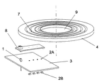
図1は、本発明によるオプトエレクトロニック回転角センサの好ましい実施例の重要な構成要素を非組み立て状態で示す。光源1、好ましくは赤外線LEDがプリント回路基板3に配置されている。光源1の光線が横方向に、使用された波長に対して透明な材料、好ましくはプレキシグラスで形成されたコードディスク4上に半径方向に照射される。ディスク4の中央には開口部9が設けられ、ここに、例えば車輛のステアリングスピンドルが、回転を許容しないように係合する。コードディスク4の内側に同心に配置された偏向面7は、半径方向光路に関して所定角度で配置された鏡面によって形成される。この鏡面で光線の偏向が全反射で生じる。
FIG. 1 shows the essential components of a preferred embodiment of the optoelectronic rotation angle sensor according to the invention in an unassembled state. A
コードディスク4の下面にはオプティカルコードが付けてある。これは、例えば、透明領域及び不透明領域の組み合わせによって形成される。コードは、オフセット印刷、レーザー法、又は特殊塗料によって付けることができる。コードを含むコードディスク4の部分は、プリント回路基板3の近くに配置される。この領域では、コードディスク4で偏向された光線を受信するため、感光受信器2A、2Bが光源1から半径方向に進む方向内にに配置されている。本発明の一実施例では、感光受信器2A、2Bはプリント回路基板3のコードディスク4に向いた側部に取り付けられ、別の実施例では、プリント回路基板3のコードディスク4に向いた側部とは反対側の側部に取り付けられる。プリント回路基板3には、感光受信器2Bの場所に開口部が設けられており、コードディスク4で偏向された光束がこの開口部を通ってフォトトランジスタ2Bに当たる。この開口部は、更に、光束を調節するためのダイアフラムとしても役立つ。追加の調節自在のダイアフラム8がコードディスク4とプリント回路基板3との間に配置されている。別の態様では、ダイアフラム8をプリント回路基板3に直接取り付けることができる。
The lower surface of the
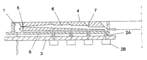
図2は、図1に示す本発明によるオプトエレクトロニック回転角センサのコードディスク4の光束6の通過を示す。光源1が発生した光束6がカップリング面5を介してコードディスクに進入する。カップリング面5は、本発明の好ましい実施例ではレンズとして作用し、光源1の末広がりの光ビームを実質的に平行に整合する。しかしながら、カップリング面5は平らであってもよい。これは、迷光損はほとんど無視できるためである。コードディスク4の内側で、光束6が半径方向内方に進む。コードディスク4は、特定の箇所に偏向面7を備えている。この偏向面は、光束6の部分を軸線方向に偏向し、そのため、光束6のこの部分がコードディスク4から出て、コードディスク4に付けてあるオプティカルコードを照らし、ダイアフラム8を通過し、感光受信器2A、2Bに当たる。
FIG. 2 shows the passage of the light beam 6 on the
光束6の偏向された部分は、各々、偏向面7の構成、及び光束6によって照射された夫々の偏向面7の鏡領域の、光束6の全断面に対する比によって得られる。偏向面7の具体的設計によって、光束6の強さを、かくして、コードディスク4の様々な領域の照光されるべきコードに亘って分割できる。偏向された光は、オプティカルコード及び光ビームの調節及び整合に使用されたダイアフラム8を通過した後、本発明の一実施例による感光受信器2Aに当たる。別の実施例では、偏向された光ビームは、プリント回路基板の開口部を通過し、感光受信器2Bに当たる。
The deflected portions of the light beam 6 are each obtained by the configuration of the deflecting
1 光源
2A、2B 感光受信器
3 プリント回路基板
4 コードディスク
5 カップリング面
6 光束
7 偏向面
8 ダイアフラム
9 開口部
DESCRIPTION OF
Claims (9)
Applications Claiming Priority (1)
| Application Number | Priority Date | Filing Date | Title |
|---|---|---|---|
| DE10325108A DE10325108A1 (en) | 2003-06-03 | 2003-06-03 | Optoelectronic rotation angle sensor |
Publications (1)
| Publication Number | Publication Date |
|---|---|
| JP2004361401A true JP2004361401A (en) | 2004-12-24 |
Family
ID=33154531
Family Applications (1)
| Application Number | Title | Priority Date | Filing Date |
|---|---|---|---|
| JP2004162719A Pending JP2004361401A (en) | 2003-06-03 | 2004-06-01 | Optoelectronic rotation angle sensor |
Country Status (5)
| Country | Link |
|---|---|
| US (1) | US20040217269A1 (en) |
| EP (1) | EP1484582A1 (en) |
| JP (1) | JP2004361401A (en) |
| CN (1) | CN1296677C (en) |
| DE (1) | DE10325108A1 (en) |
Families Citing this family (11)
| Publication number | Priority date | Publication date | Assignee | Title |
|---|---|---|---|---|
| EP1890113A1 (en) * | 2006-08-18 | 2008-02-20 | Leica Geosystems AG | Optoelectronic angle sensor and method for determining a rotation angle around an axis |
| EP2210058A4 (en) * | 2007-10-23 | 2012-05-23 | Kelsey Hayes Co | SENSOR AND METHOD FOR DETERMINING AN ANGULAR POSITION OF A ROTOR |
| DE102007052978A1 (en) * | 2007-11-07 | 2009-05-14 | Valeo Schalter Und Sensoren Gmbh | Sensor arrangement for e.g. transmission device of motor vehicle, has rotating diaphragm directing physical signal e.g. magnetic signal, of fixed optical transmitter as magnetic transducer in area in which optical receivers are arranged |
| EP2213987A1 (en) * | 2009-02-03 | 2010-08-04 | Leica Geosystems AG | Opto-electronic position measurement apparatus and opto-electronic position measurement method |
| CN102241273A (en) * | 2010-05-10 | 2011-11-16 | 上海宏曲电子科技有限公司 | Laser type digital rudder angle indication system |
| CN103407489B (en) * | 2013-08-12 | 2016-07-06 | 长沙中联重科环卫机械有限公司 | Vehicle steering device and vehicle |
| CN104567745A (en) * | 2015-01-08 | 2015-04-29 | 佛山轻子精密测控技术有限公司 | Rotary encoder based on light sensation principle and measuring method thereof |
| DE102016122585B4 (en) * | 2016-11-23 | 2018-07-12 | Preh Gmbh | Turntable with improved, optical rotary position detection |
| CN107727004B (en) * | 2017-11-13 | 2023-11-03 | 深圳中天云隼科技有限公司 | Angle sensor |
| DE102019109469A1 (en) * | 2019-04-10 | 2020-10-15 | Vishay Semiconductor Gmbh | Optical encoder |
| USD1067072S1 (en) * | 2023-11-08 | 2025-03-18 | Sick Ag | Optoelectronic sensor |
Family Cites Families (14)
| Publication number | Priority date | Publication date | Assignee | Title |
|---|---|---|---|---|
| US3731107A (en) * | 1971-12-15 | 1973-05-01 | United Aircraft Corp | Optical shaft encoder |
| SE422999B (en) * | 1980-09-03 | 1982-04-05 | Asea Ab | FIBEROPTIC SENSOR |
| JPS60155920A (en) * | 1984-01-25 | 1985-08-16 | Toyo Denso Co Ltd | Apparatus for detecting rotary position |
| US4908510A (en) * | 1988-09-02 | 1990-03-13 | The Boeing Company | Optical fiber coupled resolver having a reference signal |
| JPH1038557A (en) * | 1996-07-26 | 1998-02-13 | Alps Electric Co Ltd | Rotation angle detector for multi-rotor |
| DE19835972C1 (en) * | 1998-08-08 | 2000-01-20 | Kostal Leopold Gmbh & Co Kg | Opto-electronic position detector for industrial robot or motor vehicle |
| US6240562B1 (en) * | 1998-10-06 | 2001-06-05 | Joan Martin | Shawl type garment |
| JP2000337929A (en) * | 1999-05-25 | 2000-12-08 | Yamaha Motor Co Ltd | Meter pointer reset method and device |
| DE10006675C2 (en) * | 2000-02-15 | 2002-05-16 | Kostal Leopold Gmbh & Co Kg | Code disc for an optoelectronic displacement or angle measuring device |
| DE10036769A1 (en) * | 2000-07-28 | 2002-02-14 | Kostal Leopold Gmbh & Co Kg | Sender disk for an optoelectronic angle sensor, in particular, a steering angle sensor consists of plastic material, and is provided with optical encoding in its interior or on its surface |
| JP4862108B2 (en) * | 2001-02-02 | 2012-01-25 | 株式会社森精機製作所 | Light emitting / receiving composite unit and displacement detection device using the same |
| CN2474991Y (en) * | 2001-03-19 | 2002-01-30 | 中国科学院长春光学精密机械与物理研究所 | Photoelectric axial angle coder with intercalation structure |
| JP3624285B2 (en) * | 2001-05-14 | 2005-03-02 | 日産自動車株式会社 | Rudder angle sensor failure diagnosis device |
| US6752526B2 (en) * | 2001-11-19 | 2004-06-22 | Control Devices | Combined optical light pipe and protective enclosure |
-
2003
- 2003-06-03 DE DE10325108A patent/DE10325108A1/en not_active Ceased
-
2004
- 2004-05-06 EP EP04010817A patent/EP1484582A1/en not_active Withdrawn
- 2004-06-01 JP JP2004162719A patent/JP2004361401A/en active Pending
- 2004-06-02 US US10/858,949 patent/US20040217269A1/en not_active Abandoned
- 2004-06-02 CN CNB200410047336XA patent/CN1296677C/en not_active Expired - Fee Related
Also Published As
| Publication number | Publication date |
|---|---|
| CN1296677C (en) | 2007-01-24 |
| EP1484582A1 (en) | 2004-12-08 |
| CN1573282A (en) | 2005-02-02 |
| US20040217269A1 (en) | 2004-11-04 |
| DE10325108A1 (en) | 2005-01-05 |
Similar Documents
| Publication | Publication Date | Title |
|---|---|---|
| US6653619B2 (en) | Optical motion encoder with a reflective member allowing the light source and sensor to be on the same side | |
| US7182258B2 (en) | Enhanced reflective optical encoder | |
| JP2004361401A (en) | Optoelectronic rotation angle sensor | |
| GB2432209A (en) | Reflective optical encoders | |
| JP2006038572A (en) | Reflective encoder and electronic apparatus using the reflective encoder | |
| AU2003208299A1 (en) | Optical displacement sensor | |
| US7089672B2 (en) | Optical angle and torque sensor | |
| CN211263757U (en) | Sensor system | |
| ATE403109T1 (en) | LIGHTING SYSTEM WITH ERROR DETECTION | |
| CN100381790C (en) | Device for optoelectronic detection of switching positions of switching devices | |
| JP4524287B2 (en) | Embedded rotary encoder | |
| GB2428788A (en) | Optical encoder system, device and method of operating an optical encoding device | |
| JP3978445B2 (en) | Reflective encoder and electronic device using the same | |
| JP2588667Y2 (en) | Reflective photo sensor | |
| JP2001183174A (en) | Optical angle and/or distance measuring module and optical measured value transmitter | |
| JP3377976B2 (en) | Parallel light emitting device | |
| US6735007B2 (en) | Optoelectronic device | |
| JP2002267498A (en) | Photodetector | |
| JPS6239469Y2 (en) | ||
| EP1170737A3 (en) | Compatible optical pickup device adopting single light source | |
| JP2024111725A (en) | Detection Device | |
| JP3080630B2 (en) | Semiconductor vibration sensor | |
| JPH0142229Y2 (en) | ||
| JPH07167677A (en) | Encoder | |
| KR200265277Y1 (en) | Lens module of bar code pen scanner |
Legal Events
| Date | Code | Title | Description |
|---|---|---|---|
| A131 | Notification of reasons for refusal |
Free format text: JAPANESE INTERMEDIATE CODE: A131 Effective date: 20060810 |
|
| A02 | Decision of refusal |
Free format text: JAPANESE INTERMEDIATE CODE: A02 Effective date: 20070119 |