JP2004363073A - Fuel cell stack structure - Google Patents
Fuel cell stack structure Download PDFInfo
- Publication number
- JP2004363073A JP2004363073A JP2003280685A JP2003280685A JP2004363073A JP 2004363073 A JP2004363073 A JP 2004363073A JP 2003280685 A JP2003280685 A JP 2003280685A JP 2003280685 A JP2003280685 A JP 2003280685A JP 2004363073 A JP2004363073 A JP 2004363073A
- Authority
- JP
- Japan
- Prior art keywords
- separator
- protrusion
- fuel cell
- adhesive
- cell
- Prior art date
- Legal status (The legal status is an assumption and is not a legal conclusion. Google has not performed a legal analysis and makes no representation as to the accuracy of the status listed.)
- Granted
Links
Images










Classifications
-
- Y—GENERAL TAGGING OF NEW TECHNOLOGICAL DEVELOPMENTS; GENERAL TAGGING OF CROSS-SECTIONAL TECHNOLOGIES SPANNING OVER SEVERAL SECTIONS OF THE IPC; TECHNICAL SUBJECTS COVERED BY FORMER USPC CROSS-REFERENCE ART COLLECTIONS [XRACs] AND DIGESTS
- Y02—TECHNOLOGIES OR APPLICATIONS FOR MITIGATION OR ADAPTATION AGAINST CLIMATE CHANGE
- Y02E—REDUCTION OF GREENHOUSE GAS [GHG] EMISSIONS, RELATED TO ENERGY GENERATION, TRANSMISSION OR DISTRIBUTION
- Y02E60/00—Enabling technologies; Technologies with a potential or indirect contribution to GHG emissions mitigation
- Y02E60/30—Hydrogen technology
- Y02E60/50—Fuel cells
Landscapes
- Fuel Cell (AREA)
Abstract
【課題】 (1)はみ出した接着剤による、セル積層位置決め精度の低下を防止すること。(2)セパレータを組立治具の基準部に当てた時の、セパレータの変形による短絡を防止すること。
【解決手段】 (1)燃料電池のセパレータの縁部に、該縁部からセル面内方向に突出し燃料電池組立時に組立治具の基準部34に当てられる先端部を有する突起33を形成した燃料電池積層構造。(2)アノード側のセパレータとカソード側のセパレータとで、前記突起の位置を積層方向に見た際に重ならないようにずらした。(3)突起33がセパレータの矩形の角部近傍に形成されている。(4)隣接セパレータの周長を異ならせて接着剤溜まり41を形成した。(5)端面に曲面42またはチャンファをつけた。(6)接着剤溜まり41を突起33または突起近傍に設けた。(7)接着剤溜まり41を凹部45または凹状段部46から形成した。
【選択図】 図3PROBLEM TO BE SOLVED: (1) To prevent a decrease in cell stacking positioning accuracy due to an overflowing adhesive. (2) To prevent a short circuit due to deformation of the separator when the separator is brought into contact with the reference portion of the assembly jig.
SOLUTION: (1) A fuel in which a protrusion 33 is formed at an edge of a separator of a fuel cell, the protrusion 33 projecting inward from the edge and having a tip portion to be applied to a reference portion 34 of an assembly jig at the time of assembling the fuel cell. Battery stack structure. (2) The positions of the protrusions are shifted so that they do not overlap when viewed in the stacking direction between the anode side separator and the cathode side separator. (3) The protrusion 33 is formed near the rectangular corner of the separator. (4) The adhesive pool 41 was formed by changing the peripheral length of the adjacent separator. (5) A curved surface 42 or chamfer was provided on the end face. (6) The adhesive reservoir 41 is provided in the projection 33 or in the vicinity of the projection. (7) The adhesive reservoir 41 was formed from the concave portion 45 or the concave step portion 46.
[Selection diagram] FIG.
Description
本発明は燃料電池積層構造に関する。 The present invention relates to a fuel cell stack structure.
固体高分子電解質型燃料電池は、膜−電極アッセンブリ(MEA:Membrane-Electrode Assembly )とセパレータとの積層体からなる。膜−電極アッセンブリは、イオン交換膜からなる電解質膜とこの電解質膜の一面に配置された触媒層からなる電極(アノード、燃料極)および電解質膜の他面に配置された触媒層からなる電極(カソード、空気極)とからなる。膜−電極アッセンブリとセパレータとの間には、アノード側、カソード側にそれぞれ拡散層が設けられる。セパレータには、アノードに燃料ガス(水素)を供給するための燃料ガス流路が形成され、カソードに酸化ガス(酸素、通常は空気)を供給するための酸化ガス流路が形成されている。また、セパレータには冷媒(通常、冷却水)を流すための冷媒流路も形成されている。膜−電極アッセンブリとセパレータを重ねてセルを構成し、少なくとも1つのセルからモジュールを構成し、モジュールを積層してセル積層体とし、セル積層体のセル積層方向両端に、ターミナル、インシュレータ、エンドプレートを配置し、セル積層体をセル積層方向に締め付け、セル積層体の外側でセル積層方向に延びる締結部材(たとえば、テンションプレート)、ボルト・ナットにて固定して、スタックを構成する。 2. Description of the Related Art A solid polymer electrolyte fuel cell includes a laminate of a membrane-electrode assembly (MEA) and a separator. The membrane-electrode assembly is composed of an electrolyte membrane composed of an ion exchange membrane and an electrode (anode, fuel electrode) composed of a catalyst layer disposed on one side of the electrolyte membrane, and an electrode composed of a catalyst layer disposed on the other side of the electrolyte membrane (anode). Cathode, air electrode). A diffusion layer is provided between the membrane-electrode assembly and the separator on the anode side and the cathode side, respectively. The separator has a fuel gas flow path for supplying fuel gas (hydrogen) to the anode, and an oxidizing gas flow path for supplying oxidizing gas (oxygen, usually air) to the cathode. Further, a coolant channel for flowing a coolant (normally, cooling water) is also formed in the separator. A cell is formed by stacking a membrane-electrode assembly and a separator, a module is formed from at least one cell, the modules are stacked to form a cell stack, and terminals, insulators, and end plates are provided at both ends of the cell stack in the cell stacking direction. Are arranged, and the cell stack is fastened in the cell stacking direction, and is fixed with a fastening member (for example, a tension plate) extending in the cell stacking direction outside the cell stack with a bolt and a nut to form a stack.
各セルの、アノード側では、水素を水素イオン(プロトン)と電子にする反応が行われ、水素イオンは電解質膜中をカソード側に移動し、カソード側では酸素と水素イオンおよび電子(隣りのMEAのアノードで生成した電子がセパレータを通してくる、またはセル積層方向一端のセルのアノードで生成した電子が外部回路を通して他端のセルのカソードにくる)から水を生成するつぎの反応が行われる。 On the anode side of each cell, a reaction is performed to convert hydrogen into hydrogen ions (protons) and electrons. The hydrogen ions move through the electrolyte membrane to the cathode side, and oxygen and hydrogen ions and electrons (next MEA) on the cathode side. The following reaction is performed to generate water from the electrons generated at the anode of the cell through the separator, or the electrons generated at the anode of the cell at one end in the cell stacking direction arrive at the cathode of the other cell through an external circuit.
アノード側:H2 →2H+ +2e-
カソード側:2H+ +2e- +(1/2)O2 →H2 O
電解質膜を挟んで対峙するセパレータ同士間には、およびセパレータと電解質膜間には、接着剤が設けられて、接着・シールされ、セル化される。また、セルは位置決めされ積層されてスタック化される。特開2000−48849は、セルを積層する時に積層ずれが起こらないように、セパレータの縁に切欠部を設けておいて、該切欠部を組立治具の基準部であるガイドポストに当てる位置決め・組立方法を開示している。
Cathode: 2H + + 2e - + ( 1/2)
An adhesive is provided between separators facing each other across the electrolyte membrane and between the separator and the electrolyte membrane, and is bonded and sealed to form a cell. The cells are positioned, stacked, and stacked. Japanese Patent Application Laid-Open No. 2000-48849 discloses a positioning and positioning method in which a notch is provided at an edge of a separator so that stacking misalignment does not occur when stacking cells, and the notch is applied to a guide post as a reference portion of an assembly jig. An assembling method is disclosed.
しかし、従来の燃料電池スタックの組立方法には、つぎの課題がある。
1.セル化時に接着剤がセパレータ間から切欠部にはみ出し、このはみ出した接着剤が、セル化時およびスタック化時に、組立治具の基準部またはセルの組立治具に当てる基準面に付着し、位置決め精度が低下する。
2.セパレータを組立治具の基準部に当てた時に押し当て荷重でセパレータが変形し、電解質膜を挟んだアノード側セパレータとカソード側セパレータとが接触して電気的短絡を起こすおそれがある。
However, the conventional method of assembling a fuel cell stack has the following problems.
1. When the cell is formed, the adhesive protrudes from the gap between the separators into the notch, and when the cell is formed and the stack is formed, the adhesive adheres to the reference portion of the assembly jig or the reference surface applied to the cell assembly jig, and is positioned. Accuracy decreases.
2. When the separator is pressed against the reference portion of the assembly jig, the separator is deformed by the pressing load, and the anode-side separator and the cathode-side separator sandwiching the electrolyte membrane may come into contact with each other to cause an electric short circuit.
本発明の目的は、はみ出した接着剤の、組立治具の基準部への付着による、セル積層位置決め精度の低下を防止できる燃料電池積層構造を提供することにある。 SUMMARY OF THE INVENTION An object of the present invention is to provide a fuel cell stack structure capable of preventing a decrease in cell stacking positioning accuracy due to adhesion of a protruding adhesive to a reference portion of an assembly jig.
本発明のもう一つの目的は、セパレータを組立治具の基準部に当てた時の、セパレータの変形による短絡を防止できる燃料電池積層構造を提供することにある。 Another object of the present invention is to provide a fuel cell laminated structure capable of preventing a short circuit due to deformation of a separator when the separator is applied to a reference portion of an assembly jig.
上記目的を達成する本発明はつぎの通りである。
(1) 燃料電池のセパレータの縁部に、該縁部からセル面内方向に突出し燃料電池組立時に組立治具の基準部に当てられる先端部を有する突起を形成した燃料電池積層構造。
(2) 前記突起は、MEAとセパレータを組み合わせ単セルを構成する時に、セパレータ間またはセパレータとMEAとの間のシール材である接着剤が前記突起の先端部からはみ出さないだけの突出高さを有する(1)記載の燃料電池積層構造。
(3) 燃料電池のセパレータの縁部に該縁部からセル面内方向に突出する突起を形成し、隣接するセパレータ同士で、前記突起の位置を積層方向に見た際に重ならないようにずらした燃料電池積層構造。
(4) 前記セパレータが矩形状であり、前記突起がセパレータの矩形の角部近傍に形成されている(1)または(2)または(3)記載の燃料電池積層構造。
(5) 隣接する前記セパレータの周囲長さが異なる(1)または(3)記載の燃料電池積層構造。
(6) 前記セパレータの端面に曲面またはチャンファが形成されている(5)記載の燃料電池積層構造。
(7) 前記突起または前記セパレータの少なくとも前記突起近傍に接着剤溜まりを形成した(1)または(3)記載の燃料電池積層構造。
(8) 前記接着剤溜まりがセパレータ表面に形成された凹部または凹状段部からなる(7)記載の燃料電池積層構造。
The present invention that achieves the above object is as follows.
(1) A fuel cell laminated structure in which a protrusion is formed at an edge of a separator of a fuel cell in a cell surface direction from the edge and has a tip portion which is applied to a reference portion of an assembling jig when assembling the fuel cell.
(2) The height of the protrusion is such that the adhesive as a sealing material between the separators or between the separator and the MEA does not protrude from the tip of the protrusion when the MEA and the separator are combined to form a single cell. The fuel cell stack according to (1), comprising:
(3) A protrusion is formed at the edge of the separator of the fuel cell so as to protrude in the cell surface direction from the edge, and the adjacent separators are shifted so that the position of the protrusion does not overlap when viewed in the stacking direction. Fuel cell stack structure.
(4) The fuel cell laminate structure according to (1), (2) or (3), wherein the separator is rectangular, and the protrusion is formed near a corner of the rectangular shape of the separator.
(5) The fuel cell laminated structure according to (1) or (3), wherein adjacent separators have different peripheral lengths.
(6) The fuel cell laminated structure according to (5), wherein a curved surface or chamfer is formed on an end surface of the separator.
(7) The fuel cell laminate structure according to (1) or (3), wherein an adhesive reservoir is formed at least in the vicinity of the protrusion or the protrusion of the separator.
(8) The fuel cell laminated structure according to (7), wherein the adhesive reservoir is formed of a concave portion or a concave step formed on the surface of the separator.
上記(1)、(2)、(4)の燃料電池積層構造によれば、突起を設けてその先端部を組立治具の基準部に当てるようにしたので、突起先端部からの接着剤のはみ出しが無く、はみ出した接着剤の、組立治具の基準部への付着による、セル積層位置決め精度の低下を防止できる。
上記(3)、(4)の燃料電池積層構造によれば、隣接するセパレータ同士で(たとえば隣接するセパレータがアノード側のセパレータとカソード側のセパレータである場合、アノード側のセパレータとカソード側のセパレータとで)、積層方向に見た際の突起の位置をずらしたので、突起が変形しても突起同士が接触することがなく、セパレータを組立治具の基準部に当てた時の、セパレータの変形による短絡を防止できる。
上記(5)の燃料電池積層構造によれば、外周長が短い方のセパレータの外周面部位に接着剤を溜めることができる接着剤溜まりが形成され、セルを積層した時に接着剤がスタック外部へはみ出して組立治具の基準に付着したりセル基準面に付着するのを防止することができる。
上記(6)の燃料電池積層構造によれば、曲面またはチャンファによって接着剤溜まりを大きく形成でき、上記(5)の作用、効果が効果的に得られる。
According to the fuel cell laminate structure of (1), (2), or (4), the protrusion is provided and the front end thereof is brought into contact with the reference portion of the assembling jig. There is no protrusion, and it is possible to prevent a decrease in cell stacking positioning accuracy due to adhesion of the protruding adhesive to the reference portion of the assembly jig.
According to the fuel cell laminate structure of (3) or (4), the adjacent separators (for example, when the adjacent separator is an anode separator and a cathode separator, the anode separator and the cathode separator ), The positions of the projections are shifted when viewed in the stacking direction, so that the projections do not come into contact with each other even when the projections are deformed. Short circuit due to deformation can be prevented.
According to the fuel cell stack structure of the above (5), an adhesive pool that can store the adhesive is formed on the outer peripheral surface portion of the separator having the shorter outer peripheral length, and the adhesive flows out of the stack when the cells are stacked. It can be prevented from sticking out to the reference of the assembly jig or to the cell reference surface.
According to the fuel cell laminate structure of the above (6), the adhesive pool can be formed large by the curved surface or the chamfer, and the operation and effect of the above (5) can be effectively obtained.
上記(7)、(8)の燃料電池積層構造では、突起またはセパレータの少なくとも突起近傍部分に接着剤溜まりを設けたので、接着剤が接着剤溜まりに溜まってそれより突起先端側にはみ出るのが抑制され、組立治具の基準部への接着剤の付着が効果的に防止される。
突起先端へのはみ出しを抑制するために突起高さを大きくすると、セパレータの外形が大きくなってしまうが、本発明では接着剤溜まりで接着剤のはみ出しを抑制できるので、セパレータの外形が大きくなるのを抑制できる。
また、突起先端へのはみ出しを抑制するために接着剤塗布量を少なくするとセパレータがガスケット反力を受けた時にセパレータの変形、リークが生じるおそれがあるが、本発明のように接着剤溜まりを設けた場合は、突起先端へのはみ出しを恐れて接着剤塗布量を少なくする必要がないので、ガスケット反力を受けた時のセパレータの変形、リークの恐れもなくなる。
In the fuel cell stack structure of (7) and (8), the adhesive pool is provided at least in the vicinity of the projection or the separator, so that the adhesive is accumulated in the adhesive pool and protrudes from the protrusion tip side. It is suppressed, and the adhesion of the adhesive to the reference portion of the assembly jig is effectively prevented.
If the height of the protrusion is increased to suppress the protrusion to the protrusion tip, the outer shape of the separator increases, but in the present invention, since the protrusion of the adhesive can be suppressed by the adhesive pool, the outer shape of the separator increases. Can be suppressed.
Also, if the amount of adhesive applied is reduced to suppress the protrusion to the protrusion tip, the separator may be deformed or leaked when the separator receives a gasket reaction force, but the adhesive pool is provided as in the present invention. In this case, there is no need to reduce the amount of the adhesive to be applied to the tip of the projection because of fear of protruding to the tip of the protrusion. Therefore, there is no possibility that the separator is deformed or leaked when receiving a gasket reaction force.
以下に、本発明の燃料電池積層構造を図1〜図19(図16は比較例で、本発明に含まない)を参照して説明する。 Hereinafter, the fuel cell stack structure of the present invention will be described with reference to FIGS. 1 to 19 (FIG. 16 is a comparative example and is not included in the present invention).
本発明の燃料電池は、固体高分子電解質型燃料電池10である。該燃料電池10は、たとえば燃料電池自動車に搭載される。ただし、自動車以外に用いられてもよい。
The fuel cell of the present invention is a solid polymer
固体高分子電解質型燃料電池10は、図18、図19に示すように、膜−電極アッセンブリ(MEA:Membrane-Electrode Assembly )とセパレータ18との積層体からなる。積層体の積層方向(セル積層方向)は上下方向であってもよいし、水平方向であってもよいし、あるいは上下方向または水平方向から傾いていてもよい。膜−電極アッセンブリは、イオン交換膜からなる電解質膜11と、この電解質膜の一面に配置された触媒層12を有する電極(アノード、燃料極)14および電解質膜11の他面に配置された触媒層15を有する電極(カソード、空気極)17とからなる。触媒層12、15とセパレータ18との間には、アノード側、カソード側にそれぞれ拡散層13、16が設けられる。
As shown in FIGS. 18 and 19, the solid polymer
セパレータ18は、カーボン、または金属、または金属と樹脂(メタルセパレータと樹脂フレーム)、または導電性を付与された樹脂、の何れか、またはその組み合わせ、からなる。図示例はカーボンセパレータ(カーボンと樹脂バインダーとの混合物の成形品)の場合を示す。ただし、セパレータ18はカーボンセパレータに限るものではない。
The
セパレータ18には、アノード対向面に、アノード14に燃料ガス(水素)を供給するための燃料ガス流路27が形成され、カソード対向面に、カソード17に酸化ガス(酸素、通常は空気)を供給するための酸化ガス流路28が形成されている。また、セパレータ18には、ガス流路27、28が形成されている面と反対側の面に、冷媒(通常、冷却水)を流すための冷媒流路26も形成されている。流路26、27、28は、入口から出口まで1以上折り返して延びるサーペンタイン流路であってもよいし、あるいは入口から出口までストレートに延びるストレート流路であってもよい。
In the
セパレータ18には、セル積層方向に延びる、冷媒マニホールド29、燃料ガスマニホールド30、酸化ガスマニホールド31が形成されている。冷媒マニホールド29は冷媒流路26に連通しており、燃料ガスマニホールド30は燃料ガス流路27に連通しており、酸化ガスマニホールド31は酸化ガス流路28に連通している。望ましくは、マニホールド29、30、31は矩形状セパレータ18の対向端部に形成されており、セル面内の流路26、27、28はマニホールド形成領域を除くセパレータの中央領域に形成されている。ガス流路領域27、28でかつ電解質膜11の存在する領域は、セルの発電領域である。
On the
図18に示すように、膜−電極アッセンブリとセパレータ18を重ねてセル(単セル)19を構成し、少なくとも1つのセルからモジュール(図19は2セルで1モジュールの場合を示しているが、1セルで1モジュールを構成してもよいし、あるいは3以上のセルで1モジュールを構成してもよい)を構成し、モジュールを積層してセル積層体とし、セル積層体のセル積層方向両端に、ターミナル20、インシュレータ21、エンドプレート22を配置し、セル積層体をセル積層方向に締め付け、セル積層体の外側でセル積層方向に延びる締結部材(たとえば、テンションプレート24)、ボルト・ナット25にて固定して、燃料電池スタック23を構成する。
As shown in FIG. 18, the membrane (electrode assembly) and the
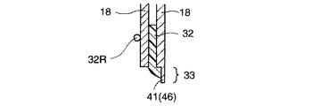
図19に示すように、流路26、27、28およびマニホールド29、30、31を外部(大気部)および異種の流体の流路および異種の流体のマニホールドから遮断するために、流路26、27、28のある発電領域まわりとマニホールド29、30、31まわりに、燃料電池10の構成部品(少なくともセパレータ18および電解質膜11を含む構成部品)間には接着剤32が配置されており、接着剤32はセルまたはモジュールの構成部品を接着するとともに、構成部品間をシールしている。接着剤32はシール剤を兼ねる。接着剤32を間に介層した2つの構成部品は、セパレータ18とセパレータ18であってもよいし、もしくはセパレータ18と電解質膜11であってもよい。
また、セル19間またはモジュール間のシールはゴムガスケット32Rに置換されてもよい。
As shown in FIG. 19, in order to shut off the
Further, the seal between the
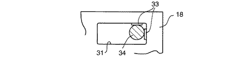
燃料電池10のセパレータ18の縁部に、縁部からセル面内方向に発電領域から離れる方向に突出し燃料電池組立時に組立治具の基準部34に当てられる先端部を有する突起33が形成される。
セパレータ18の「縁部」とは、図1〜図3(基準部34がセパレータ外部に位置する場合)に示すようにセパレータ18の外部(大気部)に面する縁部であってもよいし、あるいは図7(基準部34がマニホールド内に位置する場合)に示すように流体のマニホールド29、30、31に面する縁部であってもよい。
セパレータ18に接着剤32を塗布する場合、望ましくは、突起33の表面(セル面と平行な表面)には接着剤32を塗布しない。
また、組立治具は、セル構成部品をセル化(セル構成部品を組み合わせ、セル単体とすることをセル化という)またはモジュール化する時に構成部品の位置決めに用いる組立治具であってもよいし、セルまたはモジュールを積層してスタック化する時に積層されるセルまたはモジュールを位置決めするために用いる組立治具であってもよい。
At the edge of the
The “edge” of the
When applying the adhesive 32 to the
The assembling jig may be an assembling jig used for positioning the components when the cell components are formed into cells (combining the cell components and forming a single cell is referred to as a cell) or as a module. An assembly jig used for positioning the cells or modules to be stacked when the cells or modules are stacked and stacked.
突起33は、セル化時に、セパレータ18間に存在する接着剤32がセパレータ18の表面で押圧されて潰され拡がった時に突起33の先端部からはみ出さないだけの突出高さを有する。突起高さは、突起が無い所のセパレータの縁部に対する、セパレータ面と平行な方向の、突起33の突出高さである。突起33の突起高さは、約0.5mmであり、少なくとも0.2mm以上は必要であり、望ましくは0.3mm以上である。
図4に示すように、組立治具の基準部34が、セル積層方向に見て、突起33に対して凸の湾曲面、たとえば断面円形、である場合、突起33の形状は、セル積層方向に見て、セル積層方向と直交方向に直線状に延びる先端部をもつ。また、図5に示すように、組立治具の基準部34が、セル積層方向に見て、セパレータ縁部に対して平行な平面である場合、突起33の形状は、、セル積層方向に見て、基準部34に対して凸の湾曲面であることが望ましい。
The
As shown in FIG. 4, when the
図1〜図3に示すように、燃料電池10のセパレータ18の縁部に該縁部からセル面内方向(セル面と平行な方向)において突出する突起33を形成する場合に、アノード側のセパレータ18とカソード側のセパレータ18とで、セル積層方向に見た際に突起33の位置が重ならないように、突起33の位置をセル積層方向と直交方向に互いにずらしてある。
図1はカソード側セパレータ18に形成された突起33bの位置を示し、図2はアノード側セパレータ18に形成された突起33aの位置を示し、図3はガス流路をMEA側に向けてアノード側セパレータ18とカソード側セパレータ18でMEAを挟んでセルを構成した時の、アノード側セパレータ18の突起33aとカソード側セパレータ18の突起33bとの位置関係を示す。図3からわかるように、突起33aと突起33bとは、セル積層方向(セパレータ積層方向と同じ)に直交する方向にずれており、セル積層方向に互いに重なり合わない。
As shown in FIGS. 1 to 3, when a
FIG. 1 shows the position of a
セパレータ18は平面視で矩形状(ほぼ矩形状を含む)である場合に、突起33はセパレータ18の矩形の角部近傍に形成されることが望ましい。
When the
また、セパレータ18の、マニホールド29、30、31のうちの何れかのマニホールドの長手方向辺に対応する部分に、その長手方向辺が延びる方向と直交する方向に突出させて、突起33が形成される場合は、そのマニホールドの長手方向辺(第1の長手方向辺35)と、該第1の長手方向辺と対向し第1の長手方向辺と平行に延びる第2の長手方向辺36との間に掛け渡されて梁37が形成されており、この梁37を設けることによって、第1の長手方向辺とセパレータ縁部との間の細長いセパレータ部分38のセパレータ面内方向の剛性を高めてある。そして、突起33が組立治具の基準部34に当てられたときに細長いセパレータ部分38が撓まないように、突起33のうちマニホールドの長手方向辺の途中部位の近傍に設けられる突起33b(図2)は、梁37の近傍に設けられることが望ましい。
A
図8、図9は、本発明のとり得るもう一つの形態を示している。
図8、図9の構造においては、隣接するセパレータ18の周囲長さが異なっている。したがって、隣接するセパレータ18の一方のセパレータは他方のセパレータより一回り小さい。隣接するセパレータ18は、一つのセルの電解質膜11を挟んでその両側にある2つのセパレータ18であってもよいし、隣接するセルのアノード側セパレータとカソード側セパレータであってもよい。「周囲長さ」は、図8の例では、セパレータ外縁部の周囲長さである。ここで、セパレータ18の「周囲長さ」とは、突起33部分では、突起33の両側の突起33のない部分のセパレータ縁部をつないだ線で図った周囲長さとする。
8 and 9 show another form of the present invention.
8 and 9, the peripheral lengths of the
セル積層方向に見た場合、周囲長さが長い方のセパレータ18Aの外縁部が、周囲長さが短い方のセパレータ18Bの外縁部よりも、セパレータ面内方向(セル面と平行な方向)において、周囲長さが短い方のセパレータの外縁部と直交する方向に、外側に突出している。この突出量を図8で符号dで示してある。周囲長さが長い方のセパレータ18Aの外縁部は、周囲長さが短い方のセパレータ18Bの外縁部に対して、突起33の部位を除くセパレータ外縁部の全長にわたって突出している。これによって、図9に示すように、周囲長さが短い方のセパレータ18Bの外縁部の端面39(セル積層方向に延びる面)と、周囲長さが長い方のセパレータ18Aの外縁部のセパレータ面40(セル積層方向と直交する面)とによって、周囲長さが短い方のセパレータ18Bの外縁部の端面39の外側に、接着剤溜まり41が形成される。
When viewed in the cell stacking direction, the outer edge of the
周囲長さが長い方のセパレータ18Aに形成された突起33のセパレータ面内方向の先端位置と、周囲長さが短い方のセパレータ18Bに形成された突起33のセパレータ面内方向の先端位置とは、突起高さ方向に同じ高さ位置にあり、かつ、周囲長さが長い方のセパレータ18Aの外縁部端面より外側にあるので、周囲長さが短い方のセパレータ18Bに形成された突起33の高さD2 の方が、周囲長さが長い方のセパレータ18Aに形成された突起33の高さD1 より高く、D2 =d+D1 の関係にある。
The leading end position of the
図8は、「周囲長さ」がセパレータの外縁部の周囲長さの場合であるが、「周囲長さ」は、図10に示すように、マニホールド(冷媒マニホールド29、燃料ガスマニホールド30、酸化ガスマニホールド31)の周囲長さであってもよい。その場合は、マニホールド周囲長さが短い方のセパレータ端縁43が、マニホールド周囲長さの長い方のセパレータ端縁44よりも、マニホールド内に向かって突出して、端縁43のセパレータ面と端縁44の端面とで、接着剤溜まり41を形成する。図9は、図10の例にも同様に適用されるが、接着剤溜まり41はマニホールド周囲に形成されることになる。
FIG. 8 shows the case where the “perimeter” is the circumference of the outer edge of the separator. As shown in FIG. 10, the “perimeter” indicates the manifold (the
図8、図10の例では、図9に示すように、セパレータ18の外縁部の端面(セル積層方向に延びる面)には、外側に凸の曲面42またはチャンファが形成されてもよい。曲面42またはチャンファが形成された場合は、接着剤溜まり41の断面の大きさが、曲面またはチャンファが形成されていない場合に比べて、大きくなる。
In the examples of FIGS. 8 and 10, as shown in FIG. 9, a
また、図11〜図17に示すように、突起33またはセパレータ18の少なくとも突起33近傍に接着剤溜まり41が形成されている。
接着剤溜まり41は突起31を含むセパレータ18の表面に形成された凹部45または凹状段部46からなる。
Further, as shown in FIGS. 11 to 17, an
The
接着剤溜まり41が突起31に形成される場合は、突起31の表面のうち、セパレータの接着剤が塗布される側の面に接続する面に形成される。接着剤溜まり41が突起31に形成される場合は、図11〜図13に示すように、接着剤溜まり41は突起31の全幅(突起31の突出方向と直交する方向の全長)にわたって形成されることが望ましい。
When the
接着剤溜まり41がセパレータ18の少なくとも突起31近傍部分に形成される場合は、セパレータの接着剤が塗布される側の面に接続する面に形成される。また、接着剤溜まり41は、相対向するセパレータ18のうち両方のセパレータに形成されてもよいし(図14)、相対向するセパレータ18のうち一方のセパレータのみに形成されてもよい(図15)。また、セパレータ18の「少なくとも」突起31近傍部分とは、接着剤溜まり41が、セパレータ18の縁の全長にわたって形成されてもよいし、あるいは突起31近傍部分のみに形成されてもよい、という意味である。また、「突起31近傍部分」とは、接着剤溜まり41が、突起31に幅方向に突起31とほぼ平行に、突起31の全幅とほぼ同じ長さにわたって連続的に、かつ、マニホールドや発電領域と干渉しない位置に、形成されている、という意味である。
When the
接着剤32のセパレータ縁部からのはみ出しを防止するために接着剤32の塗布量を少なくすると、図16の比較例(本発明に含まず)に示すように、ガスケット32Rの背面に接着剤32が存在しない部分が生じてセパレータにガスケット32Rからの反力がかかった時にセパレータ18に割れが生じるおそれがあるが、図11〜図17に示すように接着剤溜まり41が形成される場合は、接着剤溜まり41によって接着剤32のセパレータ縁部からのはみ出しが防止されるので、接着剤32の塗布量を少なくする必要がなく、図16のような接着剤塗布量不足の問題は生じない。
When the amount of the adhesive 32 applied is reduced in order to prevent the adhesive 32 from protruding from the edge of the separator, as shown in a comparative example (not included in the present invention) of FIG. When the reaction force from the
つぎに、本発明の作用、効果を説明する。
セル化時およびモジュール化時、またはスタック化時、セパレータ18は組立治具の基準部34に当てられるが、突起33で基準部34に当てられる。突起先端部からの接着剤32のはみ出しはない。そのため、従来のようにセパレータ縁部からはみ出した接着剤が、組立治具の基準部に付着し、それによって、セル積層位置決め精度の低下が生じることが、起こらない。
Next, the operation and effect of the present invention will be described.
At the time of cell formation, modularization, or stacking, the
また、MEAを挟んだ、アノード側のセパレータ18の突起33aとカソード側のセパレータ18の突起33bとで、セル積層方向(セパレータ積層方向と同じ)に見た際の突起の位置を積層方向と直交する方向にずらしたので、突起33を基準部34に押し当てた反力を受けて突起33がセル積層方向に変形しても突起33aと突起33bが接触することがなく、セパレータ18を組立治具の基準部34に当てた時の、セパレータ18の変形による電気的短絡を防止できる。
In addition, the
また、マニホールド26、27、28のうち突起33の近傍に位置するマニホールドに梁37を設けた場合は、そのマニホールドと突起33が形成された縁部との間のセパレータ部分38を補強でき、突起33を基準部34に押し当てた反力を受けてもセパレータ部分38が変形することを防止できる。その結果、高精度の位置決めが可能である。また、突起33を基準部34に強く押し当てても、マニホールドと突起33が形成された縁部との間のセパレータ部分38が損傷することがなく、セパレータの強度上の信頼性も上がる。
When the
図8、図9、図10に示すように、隣接するセパレータ18の周囲長さを変えて隣接するセパレータ18のサイズを変えた場合は、サイズが小の方のセパレータ18Bの端面39(セル積層方向に延びる面、マニホールドの場合は端縁44の端面)と、サイズが大の方のセパレータ18Aのセパレータ面40(セル積層方向と直交する面、マニホールドの場合は端縁43のセパレータ面)とによって、サイズが小の方のセパレータ18Bの端面39の外側(マニホールドの場合は端縁44の端面の内側)に、接着剤溜まり41が形成されるので、隣接するセパレータ18間の接着剤32が隣接するセパレータ18で押圧されてはみ出しても、接着剤溜まり41にはみ出すだけでそれより外側にあるサイズが大の方のセパレータ18Aより外側(マニホールドの場合は端縁43の端面の内側)にはみ出すことが抑制される。したがって、接着剤32が突起33の先端部まではみ出すことはない。そのため、従来のように接着剤がセパレータ縁部からはみ出したり、あるいはセパレータ縁部からはみ出した接着剤が、組立治具の基準部に付着したりして、セル積層位置決め精度の低下が生じることは、起こらない。
As shown in FIG. 8, FIG. 9, and FIG. 10, when the size of the
また、図9に示すように、セパレータ18の外縁部またはマニホールドの端面に、曲面42またはチャンファが形成された場合は、接着剤溜まり41の断面の大きさが大きくなるので、接着剤溜まり41の、セパレータ間からはみ出した接着剤を吸収する能力が大きくなり、上記のセル積層位置決め精度の低下防止効果がより一層確実に得られる。
Further, as shown in FIG. 9, when the
また、図11〜図16、図17に示すように、突起33またはセパレータ18の少なくとも突起33近傍に接着剤溜まり41が形成されている場合は、セパレータ間からはみ出さそうとする接着剤32が接着剤溜まり41がによって吸収され、突起33の先端からはみ出すことが抑制され、突起33先端からはみ出した接着剤が、組立治具の基準部に付着したりして、セル積層位置決め精度の低下が生じることは、起こらない。
また、接着剤溜まり41が突起33またはセパレータ18の少なくとも突起33近傍に形成されているので、接着剤32の突起先端からのはみ出しが効果的に抑制される。
In addition, as shown in FIGS. 11 to 16 and 17, when the
Further, since the
また、図11〜図16、図17に示すように、接着剤溜まり41が突起31を含むセパレータ18の表面に形成された凹部45または凹状段部46から構成される場合は、接着剤溜まり41の断面の大きさが大きくなるので、接着剤溜まり41の、セパレータ間からはみ出した接着剤を吸収する能力が大きくなり、上記のセル積層位置決め精度の低下防止効果がより一層確実に得られる。
In addition, as shown in FIGS. 11 to 16 and 17, when the
10 (固体高分子電解質型)燃料電池
11 電解質膜
12、15 触媒層
13、16 拡散層
14 電極(アノード、燃料極)
17 電極(カソード、空気極)
18 セパレータ
18A 周囲長さが長い方のセパレータ
18B 周囲長さが短い方のセパレータ
19 セル
20 ターミナル
21 インシュレータ
22 エンドプレート
23 スタック
24 締結部材(テンションプレート)
25 ボルト
26 冷媒流路(冷却水流路)
27 燃料ガス流路
28 酸化ガス流路
29 冷媒マニホールド
30 燃料ガスマニホールド
31 酸化ガスマニホールド
32 接着剤
32R ガスケット
33 突起
33a アノード側セパレータの突起
33b カソード側セパレータの突起
34 組立治具の基準部
35 マニホールドの第1の長手方向辺
36 マニホールドの第2の長手方向辺
37 梁
38 第1の長手方向辺とセパレータ縁部との間の細長いセパレータ部分
39 周囲長さが短い方のセパレータ18Bの外縁部の端面
40 周囲長さが長い方のセパレータ18Aの外縁部のセパレータ面
41 接着剤溜まり
42 曲面またはチャンファ
43 マニホールド周長長さが短い方のセパレータ端縁
44 マニホールド周長長さが長い方のセパレータ端縁
45 凹部
46 凹状段部
Reference Signs List 10 (Solid polymer electrolyte type)
17 electrodes (cathode, air electrode)
18
25
27
Claims (8)
Priority Applications (1)
| Application Number | Priority Date | Filing Date | Title |
|---|---|---|---|
| JP2003280685A JP4569084B2 (en) | 2002-07-31 | 2003-07-28 | Fuel cell stack structure |
Applications Claiming Priority (3)
| Application Number | Priority Date | Filing Date | Title |
|---|---|---|---|
| JP2002223319 | 2002-07-31 | ||
| JP2003136702 | 2003-05-15 | ||
| JP2003280685A JP4569084B2 (en) | 2002-07-31 | 2003-07-28 | Fuel cell stack structure |
Publications (2)
| Publication Number | Publication Date |
|---|---|
| JP2004363073A true JP2004363073A (en) | 2004-12-24 |
| JP4569084B2 JP4569084B2 (en) | 2010-10-27 |
Family
ID=34068859
Family Applications (1)
| Application Number | Title | Priority Date | Filing Date |
|---|---|---|---|
| JP2003280685A Expired - Fee Related JP4569084B2 (en) | 2002-07-31 | 2003-07-28 | Fuel cell stack structure |
Country Status (1)
| Country | Link |
|---|---|
| JP (1) | JP4569084B2 (en) |
Cited By (8)
| Publication number | Priority date | Publication date | Assignee | Title |
|---|---|---|---|---|
| JP2005209347A (en) * | 2004-01-20 | 2005-08-04 | Honda Motor Co Ltd | Fuel cell stack and manufacturing method thereof |
| JP2007128857A (en) * | 2005-10-05 | 2007-05-24 | Nissan Motor Co Ltd | Fuel cell separator |
| JP2010129477A (en) * | 2008-11-28 | 2010-06-10 | Nissan Motor Co Ltd | Separator, and fuel cell |
| JP2012054118A (en) * | 2010-09-02 | 2012-03-15 | Toyota Motor Corp | Fuel cell |
| JP2014216247A (en) * | 2013-04-26 | 2014-11-17 | トヨタ自動車株式会社 | Fuel cell |
| JP2014220080A (en) * | 2013-05-07 | 2014-11-20 | トヨタ自動車株式会社 | Fuel cell |
| JP2020510282A (en) * | 2017-03-07 | 2020-04-02 | パワーセル スウェーデン アーベー | Fuel cell stack and bipolar plate assembly |
| CN113594592A (en) * | 2021-08-24 | 2021-11-02 | 惠州市思洋科技有限公司 | Novel cylindrical battery buckle cover assembly |
Citations (2)
| Publication number | Priority date | Publication date | Assignee | Title |
|---|---|---|---|---|
| JP2000048849A (en) * | 1998-07-31 | 2000-02-18 | Aisin Seiki Co Ltd | Fuel cell and method of assembling the same |
| JP2003142143A (en) * | 2001-11-01 | 2003-05-16 | Honda Motor Co Ltd | Fuel cell |
-
2003
- 2003-07-28 JP JP2003280685A patent/JP4569084B2/en not_active Expired - Fee Related
Patent Citations (2)
| Publication number | Priority date | Publication date | Assignee | Title |
|---|---|---|---|---|
| JP2000048849A (en) * | 1998-07-31 | 2000-02-18 | Aisin Seiki Co Ltd | Fuel cell and method of assembling the same |
| JP2003142143A (en) * | 2001-11-01 | 2003-05-16 | Honda Motor Co Ltd | Fuel cell |
Cited By (9)
| Publication number | Priority date | Publication date | Assignee | Title |
|---|---|---|---|---|
| JP2005209347A (en) * | 2004-01-20 | 2005-08-04 | Honda Motor Co Ltd | Fuel cell stack and manufacturing method thereof |
| JP2007128857A (en) * | 2005-10-05 | 2007-05-24 | Nissan Motor Co Ltd | Fuel cell separator |
| JP2010129477A (en) * | 2008-11-28 | 2010-06-10 | Nissan Motor Co Ltd | Separator, and fuel cell |
| JP2012054118A (en) * | 2010-09-02 | 2012-03-15 | Toyota Motor Corp | Fuel cell |
| JP2014216247A (en) * | 2013-04-26 | 2014-11-17 | トヨタ自動車株式会社 | Fuel cell |
| JP2014220080A (en) * | 2013-05-07 | 2014-11-20 | トヨタ自動車株式会社 | Fuel cell |
| JP2020510282A (en) * | 2017-03-07 | 2020-04-02 | パワーセル スウェーデン アーベー | Fuel cell stack and bipolar plate assembly |
| US12278405B2 (en) | 2017-03-07 | 2025-04-15 | Powercell Sweden Ab | Fuel cell stack and bipolar plate assembly |
| CN113594592A (en) * | 2021-08-24 | 2021-11-02 | 惠州市思洋科技有限公司 | Novel cylindrical battery buckle cover assembly |
Also Published As
| Publication number | Publication date |
|---|---|
| JP4569084B2 (en) | 2010-10-27 |
Similar Documents
| Publication | Publication Date | Title |
|---|---|---|
| JP4747486B2 (en) | Fuel cell | |
| JP4856006B2 (en) | Seal support diffusion media for improved fuel cell design | |
| CN101356675A (en) | solid polymer electrolyte fuel cell | |
| JP5011627B2 (en) | Fuel cell | |
| CN104577158A (en) | Resin-framed membrane electrode assembly for fuel cell | |
| JP2004207074A (en) | Fuel cell | |
| JP4569084B2 (en) | Fuel cell stack structure | |
| JP4042547B2 (en) | Fuel cell seal structure | |
| JP2007250353A (en) | Fuel cell | |
| JP2006024404A (en) | Fuel cell | |
| US7255944B2 (en) | Sealing structure of fuel cell and manufacturing method of same | |
| JP4539069B2 (en) | Fuel cell | |
| JP4752253B2 (en) | Fuel cell | |
| JP4581702B2 (en) | Fuel cell | |
| CN113299938B (en) | Separator member for fuel cell and fuel cell | |
| JP2005276781A (en) | Fuel cell separator and fuel cell stack including the same | |
| JP3636126B2 (en) | Fuel cell seal structure | |
| JP4127034B2 (en) | Fuel cell | |
| JP4507650B2 (en) | Fuel cell | |
| JP2007194124A (en) | Fuel cell | |
| CN112563527A (en) | Separator member for fuel cell and fuel cell stack | |
| JP4851722B2 (en) | Fuel cell | |
| CA2614657C (en) | Sealing structure of fuel cell and manufacturing method of same | |
| JP4013940B2 (en) | Fuel cell seal structure | |
| JP4013938B2 (en) | Fuel cell |
Legal Events
| Date | Code | Title | Description |
|---|---|---|---|
| A621 | Written request for application examination |
Free format text: JAPANESE INTERMEDIATE CODE: A621 Effective date: 20051202 |
|
| A977 | Report on retrieval |
Free format text: JAPANESE INTERMEDIATE CODE: A971007 Effective date: 20080425 |
|
| A131 | Notification of reasons for refusal |
Free format text: JAPANESE INTERMEDIATE CODE: A131 Effective date: 20080507 |
|
| A521 | Request for written amendment filed |
Free format text: JAPANESE INTERMEDIATE CODE: A523 Effective date: 20080703 |
|
| A131 | Notification of reasons for refusal |
Free format text: JAPANESE INTERMEDIATE CODE: A131 Effective date: 20081104 |
|
| A521 | Request for written amendment filed |
Free format text: JAPANESE INTERMEDIATE CODE: A523 Effective date: 20081222 |
|
| A02 | Decision of refusal |
Free format text: JAPANESE INTERMEDIATE CODE: A02 Effective date: 20091006 |
|
| A521 | Request for written amendment filed |
Free format text: JAPANESE INTERMEDIATE CODE: A523 Effective date: 20091222 |
|
| A911 | Transfer to examiner for re-examination before appeal (zenchi) |
Free format text: JAPANESE INTERMEDIATE CODE: A911 Effective date: 20100122 |
|
| TRDD | Decision of grant or rejection written | ||
| A01 | Written decision to grant a patent or to grant a registration (utility model) |
Free format text: JAPANESE INTERMEDIATE CODE: A01 Effective date: 20100713 |
|
| A01 | Written decision to grant a patent or to grant a registration (utility model) |
Free format text: JAPANESE INTERMEDIATE CODE: A01 |
|
| A61 | First payment of annual fees (during grant procedure) |
Free format text: JAPANESE INTERMEDIATE CODE: A61 Effective date: 20100726 |
|
| FPAY | Renewal fee payment (event date is renewal date of database) |
Free format text: PAYMENT UNTIL: 20130820 Year of fee payment: 3 |
|
| R151 | Written notification of patent or utility model registration |
Ref document number: 4569084 Country of ref document: JP Free format text: JAPANESE INTERMEDIATE CODE: R151 |
|
| FPAY | Renewal fee payment (event date is renewal date of database) |
Free format text: PAYMENT UNTIL: 20130820 Year of fee payment: 3 |
|
| LAPS | Cancellation because of no payment of annual fees |