【0001】
【発明の属する技術分野】
この発明は、壁面を手で打撃することによって音を発生させることが出来るような応援用具に関する。
【0002】
【従来の技術】
スポーツ観戦例えば野球の応援に際し、両手に持った2つのメガホンを互いに打ち付け合って音を出すことが盛んに行なわれている。またメガホンの代わりに合成樹脂製のおもちゃのバットを打ち合って打撃音を出すようなことも行なわれている。これ等の使用法は拍子木に倣ったものであると言うことが出来る。
【0003】
【発明が解決しようとする課題】
しかしながらこれ等の応援方法に於いては、拍子木と同様の使用法並びに構成としているため、メガホンであればメガホンを2つ必要とし、バットのおもちゃであればそれを2つ必要としている。同じようなものがペアに成っていないと、拍子木的な使い方が出来ないのである。
【0004】
そこでこの発明は、ひとつでも同様の作用効果が得られるような新規な構造の応援用具を提供しようとするものである。
【0005】
【課題を解決するための手段及び作用】
上記課題は、打撃可能な物体の壁面にその長手方向へスリットを設けて、壁面を打撃した時に前記スリットの両縁部が打ち合うようにすることにより達成される。なお前記スリットの形成個数に付いて、1以上の任意個数が可能であるために特に限定しないが、製造面や強度面などから見て1つまたは2つ程度が妥当である。
【0006】
打撃可能な物体とは、例えば上述したメガホンや中空なバットのおもちゃのような筒状体のことである。メガホン形状をしてはいてもメガホンとしての役割を担っていないようなものでも、筒状体であればその壁面などが打撃可能である。また打撃可能な物体とは、例えば単なる平板や扇状体や所謂ハリセンなどの板状体のことであって、これ等は扇子で頭をチョンと叩く仕草からも分かるように、主としてその側縁部などからの打撃が可能である。
【0007】
なお前記筒状体では次のような効果を奏する。すなわちスポーツ観戦、例えば野球の応援に際し両手に持った2つのメガホンを互いに打ち付け合って音を出すことが盛んに行なわれている。またメガホンの代わりに合成樹脂製のおもちゃのバットを打ち合って打撃音を出すようなことも行なわれている。これ等の使用法は、拍子木に倣ったものであると言うことが出来る。しかしながらこれ等の応援方法に於いては、拍子木と同様の使用法並びに構成としているため、メガホンであればメガホンを2つ必要とし、バットのおもちゃであればそれを2つ必要としている。従ってこれまでは同じものを2つ1組として購入しなくてはならないために、不必要に出費が大きくなっていたが、この発明は上述したような問題をも解決することが出来るのである。
【0008】
さて前記スリットとは、この壁面に設けられた切れ込みのことである。従って例えば前記筒状体であればそれを片方の手で持ち、もう一方の手で筒状体の壁面を打撃すると、その勢いにより前記スリットの両縁部が互いに打ち合って打撃音を発するのである。また前記板状体であればそれを片方の手で持ち、もう一方の手で板状体の側縁部などを打撃すればよい。なおスリットの幅に付いては、その両縁部が互いに打ち合い得る程度であれば特に限定されない。スリットさえ空いていれば、その両縁部が接しているような状態であっても、打撃の弾みによって音を発生することが分かっている。
【0009】
次に、前記打撃可能な物体がメガホン部を備えているものとしてもよい。前記メガホン部はメガホンとしてのみ使用され、その吹き口部で声を出すことによって拡声の作用を生ずる。従って打撃による応援とメガホンによる声援とをひとつの用具で使い分けることが出来る。
【0010】
次にスリットは前記壁面の縁部にまで達するように設ける場合と、そうでない場合とがある。前者の場合には打撃によってスリットの両縁部が比較的強く打ち合い、比較的大きな音を立てることができる。後者の場合でも打撃によってスリット回りが打ち合うため音を発生する。なお特に後者では携帯時や打撃時に於ける壁面の変形が少なくなると言う効果がある。この壁面の潰れや変形の度合いは前者では打撃可能な物体の形状や素材によって異なることが分かっている。打撃可能な物体が潰れて、スリットの両縁部が重なり合うこともある。しかしながら後者では、変形の作用そのものが生じ難いのであり、発生する音もガチャガチャ音ではなくより軽快な音になるなどの作用効果が見られる。
【0011】
なお後者の応援用具に於いて、前記壁面の、前記スリットの前記縁部側の端部と縁部との間に伸縮部が設けられているものでは、打撃時にスリットの両縁部が打ち合う際にこの伸縮部が縮まることによってこの両縁部の打ち合いがより行なわれやすくなる作用がある。当該伸縮部は、この部位のみ素材を伸縮性のあるものにしたり、蛇腹のような伸縮する構造にすることなどにより実現可能である。あるいは前者の応援用具の場合では、スリットの前記縁部側の端部と縁部との間に伸縮素材を挟み込むことによっても実現可能である。
【0012】
次に前記スリットの両縁部の肉厚が他の壁面部よりも大きいものとすることが出来る。前記スリットの両縁部が他の壁面部と同じ肉厚であるよりも、幾分なりとも厚みがあるほうが打撃がより確実なものとなる。
【0013】
また、前記スリットの両縁部に互いに打ち合うことが可能な鍔部が形成されているものとすることが出来る。前記鍔部同士は、恰かも両手を打ち合う拍手のように打ち合うため、打撃がより確実でより大きな音を立てることが出来る。
【0014】
また、前記スリットは、前記壁面の長手方向へ設けられた凸条部の中心部に、その長手方向へ向けて切り込みが入れられて成るものとすることが出来る。前記スリットをその両縁部間に僅かに隙間が出来るように形成するには、例えば前記壁面の長手方向へ凸条部を設けるように成型し、この凸条部の両側の立ち上げ部をカッターナイフなどでえぐるように切断して凸条部を除去するようにすれば、その跡には目的のスリットが形成されるのである。これはこれで良いのではあるが、前記凸条部の両側に対してカッターナイフなどでえぐると言う作業が要請されるので、さらに工程を簡単なものにするには次のようにすれば良い。すなわち凸条部の中心部にその長手方向へ向けて切り込みを入れて成るものとするのである。
【0015】
なお更に、前記凸条部の中心部が鋭角に形成されているものとすることが出来る。この鋭角に形成されている部分にカッターナイフを刺し入れ、ここに添って切れ込みを入れて行けば、前記鋭角部分がガイドの役目を担って一条のスリットが形成される。従って前記凸条部の両側をぐるりとえぐらずとも、前記凸条部の中心部に一本の切れ込みを入れるだけであるから、作業が極めて楽でありコストにも良い影響を及ぼす。なお前記凸条部の中心部が鋭角に形成されているため、ここがカッターナイフのガイドと成る作用効果がある。
【0016】
また、前記スリットは、前記壁面の長手方向へ設けられた凹条部の中心部に、その長手方向へ向け切り込みが入れられて成るものとすることが出来る。これは前記前記凸条部とは反対側(壁面の内側方向)への凸条部と言うことになるが、カッターナイフなどでえぐる作業を行なった結果は上述した凸条部の場合と同一である。しかしながら、前記凹条部の中心部が鋭角に形成されているものとした場合では、この鋭角に形成されている部分に添って一条の切れ込みを入れて行けばスリットが形成される点は同一であるものの、スリットがある凸条部が壁面の内側へ向き、壁面の外側へは出て来ないため、比較的見た目が良いと言う利点がある。
【0017】
【発明の実施の形態】
以下、本発明の実施形態に付き、図面に基づいて説明するが、本発明はこれらの実施形態にのみ限定されるものではない。なおこれらの実施形態に於ける要部は合成樹脂成型によるものの例である。
【0018】
(第1実施形態)
図1で表わした応援用具は、打撃可能な物体として合成樹脂によって扇状体1に成型して成るものである。この扇状体1の中心部からは外縁部に至るスリット11が設けられている。このスリット14の幅すなわち両縁部間の距離を5ミリメートルほど取っており、スリット11の両縁部には鍔部12,12が形成されている。またこの扇状体1の両側には手で打撃するための側板10が設けられている。なおこの扇状体1には握り部13が設けられている。
【0019】
この扇状体1は弾力性のある合成樹脂製のものであるから、握り部13を片手で握り、もう一方の手で前記側板10を打撃すると、打撃の弾みによりスリット11の両縁部の鍔部12,12が互いに打ち合って打撃音を発生する。また所謂ハリセンのような使い方が可能である。このように数ミリメートルの隙間がある場合もスリットであり、打撃の衝撃でスリットの両縁部が互いに打ち合うことが出来るわけであるが、この実施形態では鍔部12,12が形成されているため、より確実に打ち合うことが可能と成っている。なおこの応援用具は、扇のように扇ぐ仕草での応援にも使用することが出来る。
【0020】
(第2実施形態)
図2及び図3で表わした応援用具は、打撃可能な物体として合成樹脂によって筒状体2に成型して成るものである。この筒状体2は野球のバットをデフォルメした形状と成っており、細い方の側は握り部20として筒形が閉じられており、太い方の側には開口部21が設けられている。この筒状体2の壁面にはその長手方向へ向けて、開口部21にまで達するスリット22を形成した。このスリット22は、筒状体2の壁面をカッターナイフで切り込んで付けたものである。この横断面形状を模式的に表わしたものが図3であるが、前記筒状体2の壁面にその長手方向へ向けて、開口部21にまで達するスリット22を、2回対称の位置に2つ形成すると共に、このスリット22の両縁部に筒状体2の内側に向けて鍔部23,23を形成した。なおこのメガホンは図3の上方向または下方向から打撃するものであるが、打撃する部位の目安とすべく略円形状の打撃部24を設けている。ここには絵柄を入れたりシールを貼ったりすることが出来る。
【0021】
この応援用具は中空状で軽量であるから、片手で握り部20を握り楽々と取り扱うことが可能である。握り部20の端部は閉じられており、強度は十分に確保されている。そこでもう一方の手で前記打撃部24あたりを打撃することによって音を出すことが出来る。この時、スリット22の両縁部に設けられている鍔部23,23同士が恰かも両手を打ち合う拍手のように打ち合うため、打撃がより確実でより大きな音を立てることに成る。
【0022】
(第3実施形態)
図4で表わした応援用具は、打撃可能な物体として合成樹脂によって成型された筒状体3,3を、握柄兼用のマラカス部30の両側に設けて成るものである。即ち、この筒状体3の壁面にその長手方向へ向けて、前記筒状体3の中央部付近から開口部32の約2センチメートル手前まで延びるスリット31を形成した。なおこのスリット31は前記筒状体3,3の壁面をカッターナイフで切り込んで付けたものであり、各々の筒状体3に付いて6回対称の位置に6条のスリットが設けられている。また前記マラカス部30は閉じられており、その内部には合成樹脂ペレットが所要量だけ納められている。
【0023】
この応援用具は握柄がマラカス部30と成っているため、ここを持って振るだけで合成樹脂ペレットが筒状体3に当たってマラカスの音を出すことが出来る。他方マラカス部30を片手で握って、もう一方の手で筒状体3の壁面を打撃すると、その勢いにより前記スリット31の両縁部が互いに打ち合って打撃音を発する。この時の打撃の位置は任意であり、何れかのスリット31の両縁部が互いに打ち合って打撃音を発する。スリット31は筒状体3の壁面を切り込んで付けただけのものであるから、スリット31の両縁部分は互いに付かず離れずのような状態ではあるが、打撃の弾みにより互いに打ち合って音を発生し、これが筒状体3に伝わって響くように聞こえる。
【0024】
またこの際、スリット31は前記開口部32にまで達していないが、打撃時の衝撃でスリット31回りが打ち合うために音を発生するのである。この際に発生する音はガチャガチャ音ではなく軽快な音である。また特にスリット31が開口部32にまで達していないことによって、スリット31の近くの壁面を打撃した場合に、開口部32が潰れてスリット31の両縁部の打ち合いが弱くなり、音が弱くなると言うようなことが起こらず、携帯時や打撃時等に於ける開口部32の壁面の変形が少なくなるという効果がある。
【0025】
(第4実施形態)
図5及び図6で表わした応援用具は、打撃可能な物体として合成樹脂によって成型されたメガホン様の筒状体4に関するものであるが、メガホンとしての機能を備えないため握り部40には吹き口は設けられていない。この実施形態の特徴は筒状体4の壁面に設けられたスリット42の構成にある。すなわちこの筒状体4の壁面にその長手方向へ向けて前記筒状体4の中央部付近から開口部41にまで達する凹部43を形成し、この凹部43の底部にカッターナイフを入れるようにして、開口部41の手前2センチメートルまで切り裂いてスリット42を設けて成る。なお前記凹部43は筒状体4の内側に向けて突出している。この先端部が略V字形状に凹設された凹部43は、カッターナイフを用いてここを切り裂く際のガイド性が良好である。また凹部43はV字形状の先端部へ近付くほど肉薄と成っているため、切り裂きやすいという利点がある(図6)。
【0026】
この実施形態では、前記凹部43は開口部41まで達するように形成されているが、前記スリット42は開口部41の2センチメートル手前までであり、開口部41にまでは達していない点に特徴を有する。すなわちこの2センチメートルの間は略V字形状の凹部43のみ形成された形と成っており、凹部43には打撃の力が加わりやすく、蛇腹のように縮小しやすく、これにより一層効率的に前記スリット42の両縁部を叩き合わせる。なお前記凹部43は筒状体4の外側から見ると凹部であって、筒状体4の内側方向へ突出しているものであり、筒状体4の外側へは出て来ていないため、比較的見た目が良いと言う利点がある。
【0027】
(第5実施形態)
図7及び図8で表わした応援用具は、上述した第4実施形態と同様の筒状体5と握り部50とを備えるが、この握り部50に吹き口は設けられていない。この筒状体5にその長手方向へ向けて前記筒状体5の中央部付近から開口部まで達する凹部53を形成し、この凹部53の底部にカッターナイフを入れるようにして開口部に至るスリット52を設ける。またさらにこの開口部に補強筒51を被せて成る。なお前記凹部53は全体が略U字形状を呈し、筒状体5の内側に向けて突出している(図8)。
【0028】
この応援用具では、スリット52は凹部53と共に筒状体5の開口部に至るまで形成されているが、開口部に補強筒51が被せられていることによって、スリット52は実質的には補強筒51の手前までしか形成されていないことに成る。従って上述した第4実施形態の応援用具と同様の作用効果を奏する。なお補強筒51を取り付ける代わりに、この部位にビニールテープ等のテープを捲き付ける構成も可能である。
【0029】
(第6実施形態)
さて上述した第4及び第5実施形態では凹部43,53を筒状体4,5の内側に向けて突設していた。これに対してこの第6実施形態および次に説明する第7実施形態では凸部61,71としている。すなわちこの第6実施形態は、筒状体壁面6の長手方向へ向け先端部が略V字形状に設けられた凸部61の前記先端部に切り込みが入れられてスリット60が形成されている。なお凸部61は筒状体壁面6の外側に向けて突出している(図9)。
【0030】
凸部61の先端部が略V字形状に突設されており、先端部にカッターナイフを入れて切り裂く際のガイド性が良好であるという利点がある。
【0031】
(第7実施形態)
図10はこの実施形態の一部分である筒状体壁面7を拡大して表わしたものである。筒状体壁面7の長手方向へ設けられた凸部71の中心部に、その長手方向に向けて切り込みが入れられてスリット70が形成されている。なお凸部71はその全体が略U字形状を呈している。
【0032】
なお前記凸部71は筒状体壁面7の外側から見ると凸部であり、筒状体壁面7の外側方向へ突出しているものである。
【0033】
(第8実施形態)
図11はこの実施形態の一部分である筒状体壁面8を拡大して表わしたものであるが、この筒状体壁面8の長手方向へ向けて形成されたスリット80の両縁部の肉厚が他の壁面部よりも大きい肉厚部81と成っている点に特徴を有する。
【0034】
この肉厚部81の存在によって打撃がより確実なものと成り、音がよいと言う効果がある。
【0035】
(第9実施形態)
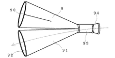
図12で表わした応援用具は、打撃可能な物体として合成樹脂により成型されたメガホン様の、しかしメガホンとしての機能を備えていない筒状体9と、メガホンの拡声部91とを、共有する1つの握り部93によって束ねて成るものであり、前記筒状体9側はこの握り部93とは通気しないが、前記拡声部91と握り部93とは通気するように構成されている。符号94は握り部93に設けられた吹き口部である。前記拡声部91の端部は拡声口とされており、また前記筒状体9の端部は開口部90とされている。而して筒状体9の壁面の、前記筒状体9の中央部付近から開口部90にまで達する部位に、その長手方向へ向けてカッターナイフを入れるようにして切り裂いてスリット90を設けて成る。
【0036】
前記握り部93を片手で握ってもう一方の手で筒状体9の壁面を打撃すると、その勢いにより前記スリット90の両縁部が互いに打ち合って打撃音を発する。このスリット90は筒状体9の壁面を切り込んで付けただけのものであるから、スリット90の両縁部分は互いに付かず離れずのような状態ではあるが、打撃の弾みにより互いに打ち合って音を発生し、これが筒状体9に伝わり主として開口部90から発せられて響くように聞こえる。
【0037】
一方で、前記吹き口部94に口を当てて発生すると、その声は通気のある前記拡声部91の側へ流れ、拡声口92から発せられる。このようにこの実施形態の応援用具は、打撃音を発生するのみならずメガホンとしての利用法がある。このような形態もあり得るのである。
【0038】
(その他)
なおこの他、スリットの両縁部に壁面の他の部位とは異なる材料から成る互いに叩き遭う部材を付けることが出来る。例えば他よりも硬い材料を用いるようにするなどである。前記打撃可能な物体が筒状体である場合に、その形状は円筒形に拘らないから、例えば角丸の方形などが任意に採用可能である。また機能ではなく形状のみ従来のメガホン形状とすることが可能である。またこの素材に関しても任意である。またこの発明の応援用具に紐通しのための孔を設けることなども可能である。
【0039】
またスリットが外側から見えなくなるように、スリットの上にビニール製等のシールを、このシールの中央部分がスリットに接着しないようにしてスリットの周縁部で壁面に接着するなどの工夫が可能である。この構成によってもスリットからは打撃音を発生させることが出来るのである。なお例えば上述した第4実施形態では、凹部43の底部にカッターナイフを入れるようにしてスリット42を刻設しているが、凹部43の周囲を切り取るようにして幅広のスリットを設けることが可能である。
【0040】
【発明の効果】
以上この発明の応援用具は、打撃可能な物体の壁面にスリットを設けただけの簡易構造でありながら、拍子木のように打撃音を発生させることが出来る。
【0041】
この結果、従来品では同じものを2つ揃える必要があったのに対して、この発明では単体でこのような打撃音を発生させることが可能と成っている。
【図面の簡単な説明】
【図1】第1実施形態の斜視図である。
【図2】第2実施形態の縦断面図である。
【図3】同実施形態の横断面模式図である。
【図4】第3実施形態の斜視図である。
【図5】第4実施形態の斜視図である。
【図6】同実施形態の横断面一部模式図である。
【図7】第5実施形態の斜視図である。
【図8】同実施形態の横断面一部模式図である。
【図9】第6実施形態の横断面一部模式図である。
【図10】第7実施形態の横断面一部模式図である。
【図11】第8実施形態の横断面一部模式図である。
【図12】第9実施形態の斜視図である。
【符号の説明】
1 扇状体
10 側板
11 スリット
12 鍔部
13 握り部
2 筒状体
20 握り部
21 開口部
22 スリット
23 鍔部
24 打撃部
3 筒状体
30 マラカス部
31 スリット
32 開口部
4 筒状体
40 握り部
41 開口部
42 スリット
43 凹部
5 筒状体
50 握り部
51 補強筒
52 スリット
53 凹部
6 筒状体壁面
60 スリット
61 凸部
7 筒状体壁面
70 スリット
71 凸部
8 筒状体壁面
80 スリット
81 肉厚部
9 筒状体
90 開口部
91 拡声部
92 拡声口
93 握り部
94 吹き口部[0001]
BACKGROUND OF THE INVENTION
The present invention relates to a support tool that can generate sound by hitting a wall surface with a hand.
[0002]
[Prior art]
When watching sports games such as baseball, the two megaphones held in both hands are often struck together to produce sound. In addition, instead of megaphones, hitting a synthetic resin toy bat and making a hitting sound are also being made. It can be said that these usages are modeled after time trees.
[0003]
[Problems to be solved by the invention]
However, in these support methods, the usage and configuration are the same as those of the time tree, so two megaphones are required for a megaphone and two are required for a bat toy. If the same thing is not paired, it cannot be used like a beat.
[0004]
Therefore, the present invention is intended to provide a support tool having a novel structure that can achieve the same effect even if one is used.
[0005]
[Means and Actions for Solving the Problems]
The above-mentioned subject is achieved by providing a slit in the wall surface of an object that can be struck in the longitudinal direction so that both edges of the slit will strike when the wall surface is struck. The number of slits formed is not particularly limited because an arbitrary number of 1 or more is possible, but about one or two is appropriate from the viewpoint of manufacturing and strength.
[0006]
The hitable object is a cylindrical body such as the above-described megaphone or hollow bat toy. Even if it has a megaphone shape but does not play a role as a megaphone, its wall surface or the like can be hit if it is a cylindrical body. Further, the hitable object is, for example, a flat plate, a fan, or a plate-like body such as a so-called harsen, which is mainly a side edge portion as can be seen from a gesture of hitting the head with a fan. It is possible to hit from.
[0007]
The cylindrical body has the following effects. In other words, when watching sports games, for example, supporting baseball, two megaphones held in both hands are struck against each other to produce sound. In addition, instead of megaphones, hitting a synthetic resin toy bat and making a hitting sound are also being made. It can be said that these usages are modeled after time trees. However, in these support methods, the usage and configuration are the same as those of the time tree, so two megaphones are required for a megaphone and two are required for a bat toy. Therefore, until now, the same items have to be purchased as a set, so the expense has been increased unnecessarily. However, the present invention can also solve the above-described problems.
[0008]
The slit is a notch provided on the wall surface. Therefore, for example, if the cylindrical body is held with one hand and the wall of the cylindrical body is hit with the other hand, both edges of the slit strike each other due to the momentum, and a hitting sound is generated. is there. Moreover, if it is the said plate-shaped body, it should just hold it with one hand and strike a side edge part etc. of a plate-shaped body with the other hand. Note that the width of the slit is not particularly limited as long as both edge portions can strike each other. It has been found that as long as the slits are vacant, even if the edges are in contact with each other, sound is generated by the impact of striking.
[0009]
Next, the hitable object may include a megaphone unit. The megaphone unit is used only as a megaphone, and produces a loud sound effect by producing a voice at its mouth. Therefore, support by striking and cheering by megaphone can be used properly with one tool.
[0010]
Next, the slit may be provided so as to reach the edge of the wall surface or not. In the former case, both edges of the slit strike relatively strongly by striking and a relatively loud sound can be made. Even in the latter case, sound is generated because the area around the slit hits by the impact. In particular, the latter has the effect of reducing deformation of the wall surface when carrying or hitting. It has been found that the degree of crushing and deformation of the wall surface differs depending on the shape and material of the object that can be hit in the former case. The object that can be struck may be crushed and the edges of the slit may overlap. However, in the latter case, it is difficult for the deformation action itself to occur, and an action effect such as a lighter sound is generated instead of a rattling sound.
[0011]
In the latter cheering tool, in the case where an expansion / contraction part is provided between the edge of the wall on the edge side of the slit and the edge, when both edges of the slit hit each other at the time of impact Further, the contraction of the expansion / contraction part has an effect that the both edges are more easily hit. The stretchable part can be realized by making the material stretchable only at this part, or by making the structure stretchable like a bellows. Or in the case of the former support tool, it is realizable also by pinching an expansion-contraction material between the edge part and edge part of the said edge part side of a slit.
[0012]
Next, the wall thickness of the both edge parts of the said slit can be made larger than another wall surface part. The hitting is more reliable when the edges of the slits are somewhat thicker than the other wall surfaces.
[0013]
Moreover, the collar part which can be hit | abutted mutually can be formed in the both edges of the said slit. The buttocks hit each other like applause that strikes both hands, so that the hitting is more reliable and a louder sound can be made.
[0014]
The slit may be formed by cutting a central portion of a ridge portion provided in the longitudinal direction of the wall surface in the longitudinal direction. In order to form the slit so that there is a slight gap between both edges, for example, the slit is formed in the longitudinal direction of the wall surface so as to be provided with a protruding portion, and the rising portions on both sides of the protruding portion are cut by a cutter. If the protrusion is removed by cutting with a knife or the like, the target slit is formed at the trace. This is fine, but since it is required to work with a cutter knife etc. on both sides of the ridge, the following steps can be taken to further simplify the process. . That is, a cut is made in the central portion of the ridge portion in the longitudinal direction.
[0015]
Still further, the central portion of the ridge portion may be formed at an acute angle. If a cutter knife is inserted into the portion formed at the acute angle and a notch is formed along the cutter knife, the acute angle portion serves as a guide to form a single slit. Therefore, since it is only necessary to make a single notch in the central portion of the ridge portion without going through both sides of the ridge portion, the operation is extremely easy and the cost is positively affected. In addition, since the center part of the said protruding item | line part is formed in the acute angle, there exists an effect which becomes here a guide of a cutter knife.
[0016]
In addition, the slit may be formed by cutting in the longitudinal direction at the center of the concave portion provided in the longitudinal direction of the wall surface. This is a ridge on the opposite side (inward direction of the wall surface) of the ridge, but the result of performing the operation with a cutter knife or the like is the same as in the case of the ridge described above. is there. However, in the case where the central portion of the concave portion is formed at an acute angle, the slit is formed if the slit is formed along the portion formed at the acute angle. However, there is an advantage that the ridge portion with the slit faces inward of the wall surface and does not come out of the wall surface, so that it looks relatively good.
[0017]
DETAILED DESCRIPTION OF THE INVENTION
Hereinafter, although it attaches to the embodiment of the present invention and explains based on a drawing, the present invention is not limited only to these embodiments. In addition, the principal part in these embodiment is an example of what is based on synthetic resin molding.
[0018]
(First embodiment)
The support tool shown in FIG. 1 is formed by molding the fan-shaped body 1 with a synthetic resin as a hitable object. A slit 11 is provided from the center of the fan 1 to the outer edge. The width of the slit 14, that is, the distance between both edge portions is set to about 5 millimeters, and flanges 12 and 12 are formed on both edge portions of the slit 11. Further, side plates 10 for hitting by hand are provided on both sides of the fan 1. The fan 1 is provided with a grip 13.
[0019]
Since this fan-shaped body 1 is made of an elastic synthetic resin, if the grip portion 13 is grasped with one hand and the side plate 10 is struck with the other hand, the edges of the slits 11 at the edges of the slit 11 are struck by the impact of the impact. The parts 12 and 12 strike each other to generate a striking sound. In addition, it can be used like a so-called Haricen. In this way, even when there is a gap of several millimeters, it is a slit, and both edges of the slit can hit each other by impact of impact, but in this embodiment, the flanges 12 and 12 are formed. It is possible to meet more reliably. In addition, this support tool can be used also for support with the gesture which flies like a fan.
[0020]
(Second Embodiment)
The cheering tool shown in FIGS. 2 and 3 is formed into a cylindrical body 2 with a synthetic resin as an object that can be struck. The tubular body 2 has a deformed shape of a baseball bat. The tubular side is closed as a grip 20 on the thin side, and an opening 21 is provided on the thick side. A slit 22 reaching the opening 21 was formed in the wall surface of the cylindrical body 2 in the longitudinal direction. The slit 22 is formed by cutting the wall surface of the cylindrical body 2 with a cutter knife. FIG. 3 schematically shows the cross-sectional shape, but the slit 22 reaching the opening 21 toward the longitudinal direction on the wall surface of the cylindrical body 2 is located at a two-fold symmetrical position. In addition, the flanges 23 and 23 were formed on both edges of the slit 22 toward the inside of the cylindrical body 2. The megaphone strikes from above or below in FIG. 3, but a substantially circular hitting portion 24 is provided as a guide for the hitting portion. You can put a picture or stick a sticker here.
[0021]
Since this support tool is hollow and lightweight, it is possible to easily handle the grip portion 20 with one hand. The end portion of the grip portion 20 is closed, and the strength is sufficiently secured. Therefore, a sound can be produced by hitting the hitting portion 24 with the other hand. At this time, since the flanges 23, 23 provided on both edges of the slit 22 strike each other like claps that strike both hands, the hitting is more reliable and makes a louder sound.
[0022]
(Third embodiment)
The support tool shown in FIG. 4 is formed by providing cylindrical bodies 3 and 3 formed of synthetic resin as objects that can be struck on both sides of the maracas portion 30 that also serves as a handle. That is, a slit 31 extending from the vicinity of the center of the cylindrical body 3 to about 2 centimeters before the opening 32 is formed on the wall surface of the cylindrical body 3 in the longitudinal direction. The slits 31 are formed by cutting the wall surfaces of the cylindrical bodies 3 and 3 with a cutter knife, and six slits are provided at positions that are six-fold symmetrical with respect to each cylindrical body 3. . The maraca portion 30 is closed, and a required amount of synthetic resin pellets are accommodated therein.
[0023]
Since this support tool has a handle as the maraca portion 30, the synthetic resin pellets can hit the cylindrical body 3 and make a maraca sound just by holding and shaking it. On the other hand, when the maraca portion 30 is grasped with one hand and the wall surface of the cylindrical body 3 is hit with the other hand, both edges of the slit 31 hit each other by the momentum to generate a hitting sound. The position of the hitting at this time is arbitrary, and both edge portions of any one of the slits 31 hit each other to generate a hitting sound. Since the slits 31 are formed by cutting the wall surface of the cylindrical body 3, both edge portions of the slits 31 are not attached to each other and are not separated from each other. It sounds like it is transmitted to the cylindrical body 3 and resonates.
[0024]
Further, at this time, the slit 31 does not reach the opening 32, but a sound is generated because the periphery of the slit 31 hits by an impact at the time of impact. The sound generated at this time is not a messy sound but a light sound. In particular, when the slit 31 does not reach the opening 32, and the wall near the slit 31 is hit, the opening 32 is crushed and the striking of both edges of the slit 31 becomes weak and the sound becomes weak. This does not happen, and there is an effect that deformation of the wall surface of the opening 32 when carrying or hitting is reduced.
[0025]
(Fourth embodiment)
The support tool shown in FIGS. 5 and 6 relates to a megaphone-like tubular body 4 molded of synthetic resin as an object that can be struck, but since it does not have a function as a megaphone, There is no mouth. The feature of this embodiment is the configuration of the slit 42 provided on the wall surface of the cylindrical body 4. That is, a concave portion 43 is formed on the wall surface of the cylindrical body 4 so as to extend in the longitudinal direction from the vicinity of the central portion of the cylindrical body 4 to the opening 41, and a cutter knife is inserted into the bottom of the concave portion 43. The slit 42 is formed by cutting up to 2 cm before the opening 41. The recess 43 protrudes toward the inside of the cylindrical body 4. The concave portion 43 in which the tip portion is recessed in a substantially V shape has good guide characteristics when the cutter knife is used to cut the concave portion 43. Moreover, since the recessed part 43 is so thin that it approaches the V-shaped front-end | tip part, there exists an advantage that it is easy to tear (FIG. 6).
[0026]
In this embodiment, the recess 43 is formed so as to reach the opening 41, but the slit 42 is up to 2 centimeters before the opening 41 and does not reach the opening 41. Have That is, between the two centimeters, only a substantially V-shaped concave portion 43 is formed, and the concave portion 43 is easily subjected to a striking force and is easily reduced like an accordion, thereby more efficiently. The both edges of the slit 42 are struck together. The concave portion 43 is a concave portion when viewed from the outside of the cylindrical body 4 and protrudes inward of the cylindrical body 4 and does not come out of the cylindrical body 4. There is an advantage that it looks good.
[0027]
(Fifth embodiment)
7 and 8 includes the cylindrical body 5 and the grip part 50 similar to those of the above-described fourth embodiment, but the grip part 50 is not provided with a blowing port. A concave portion 53 is formed in the cylindrical body 5 so as to extend in the longitudinal direction from the vicinity of the central portion of the cylindrical body 5 to the opening, and a slit reaching the opening is formed by inserting a cutter knife into the bottom of the concave portion 53. 52 is provided. Further, the opening is covered with a reinforcing cylinder 51. In addition, the said recessed part 53 is substantially U-shaped, and protrudes toward the inner side of the cylindrical body 5 (FIG. 8).
[0028]
In this cheering tool, the slit 52 is formed to reach the opening of the cylindrical body 5 together with the recess 53, but the slit 52 is substantially a reinforcing cylinder by covering the opening with the reinforcing cylinder 51. It is formed only up to 51. Therefore, there exists an effect similar to the support tool of 4th Embodiment mentioned above. Instead of attaching the reinforcing cylinder 51, a configuration in which a tape such as a vinyl tape is wound around this portion is also possible.
[0029]
(Sixth embodiment)
In the fourth and fifth embodiments described above, the recesses 43 and 53 are provided so as to project toward the inside of the cylindrical bodies 4 and 5. On the other hand, the convex portions 61 and 71 are used in the sixth embodiment and the seventh embodiment described below. That is, in the sixth embodiment, the slit 60 is formed by cutting the tip portion of the convex portion 61 having the tip portion provided in a substantially V shape in the longitudinal direction of the cylindrical wall surface 6. In addition, the convex part 61 protrudes toward the outer side of the cylindrical body wall surface 6 (FIG. 9).
[0030]
The tip portion of the convex portion 61 protrudes in a substantially V shape, and there is an advantage that the guide property when the cutter knife is inserted into the tip portion and cut is good.
[0031]
(Seventh embodiment)
FIG. 10 is an enlarged view of the cylindrical wall surface 7 which is a part of this embodiment. A slit 70 is formed by cutting the central portion of the convex portion 71 provided in the longitudinal direction of the cylindrical wall surface 7 toward the longitudinal direction. In addition, the convex part 71 has the substantially U shape as a whole.
[0032]
The convex portion 71 is a convex portion when viewed from the outside of the cylindrical body wall surface 7, and protrudes toward the outer side of the cylindrical body wall surface 7.
[0033]
(Eighth embodiment)
FIG. 11 is an enlarged view of the cylindrical body wall surface 8 which is a part of this embodiment. The thickness of both edges of the slit 80 formed in the longitudinal direction of the cylindrical body wall surface 8 is shown. Is characterized in that it is formed with a thicker portion 81 than the other wall surface portion.
[0034]
The presence of the thick portion 81 has an effect that the hitting is more reliable and the sound is good.
[0035]
(Ninth embodiment)
The support tool shown in FIG. 12 shares a megaphone-like cylindrical body 9 that is molded of a synthetic resin as a hitable object, but does not have a function as a megaphone, and a megaphone loudspeaker 91. The grip portion 93 is bundled, and the tubular body 9 side does not ventilate the grip portion 93, but the loudspeaker portion 91 and the grip portion 93 are configured to vent. Reference numeral 94 denotes an air outlet provided in the grip portion 93. An end portion of the loudspeaker portion 91 is a loudspeaker, and an end portion of the cylindrical body 9 is an opening 90. Thus, a slit 90 is provided by cutting the wall surface of the cylindrical body 9 so as to insert a cutter knife in the longitudinal direction at a portion reaching from the vicinity of the central portion of the cylindrical body 9 to the opening 90. Become.
[0036]
If the wall of the cylindrical body 9 is hit with one hand while holding the grip 93 with one hand, both edges of the slit 90 strike each other by the momentum to generate a hitting sound. Since the slit 90 is formed by cutting the wall surface of the cylindrical body 9, both edge portions of the slit 90 are not attached to each other and are not separated from each other. A sound is generated, which is transmitted to the cylindrical body 9 and is emitted mainly from the opening 90 to sound.
[0037]
On the other hand, when the sound is generated by hitting the mouth part 94, the voice flows toward the sounding part 91 having ventilation and is emitted from the sounding part 92. As described above, the support tool of this embodiment can be used as a megaphone as well as generating a hitting sound. Such a form is also possible.
[0038]
(Other)
In addition to this, it is possible to attach members hitting each other made of a material different from other portions of the wall surface to both edges of the slit. For example, a material harder than others is used. When the hittable object is a cylindrical body, the shape is not limited to a cylindrical shape, and for example, a rounded square shape can be arbitrarily adopted. Further, only the shape, not the function, can be changed to the conventional megaphone shape. This material is also optional. It is also possible to provide a stringing hole in the support tool of the present invention.
[0039]
In addition, it is possible to devise such that a slit made of vinyl or the like is attached on the slit, and the center portion of the seal is not bonded to the slit, and is bonded to the wall surface at the peripheral edge of the slit so that the slit is not visible from the outside. . Even with this configuration, a striking sound can be generated from the slit. For example, in the above-described fourth embodiment, the slit 42 is engraved so as to insert a cutter knife into the bottom of the recess 43, but it is possible to provide a wide slit so as to cut out the periphery of the recess 43. is there.
[0040]
【The invention's effect】
As described above, the support tool of the present invention can generate a striking sound like a beat tree, while having a simple structure in which a slit is provided on the wall surface of a strikeable object.
[0041]
As a result, it is necessary to prepare the same two in the conventional product, but in the present invention, it is possible to generate such a hitting sound by itself.
[Brief description of the drawings]
FIG. 1 is a perspective view of a first embodiment.
FIG. 2 is a longitudinal sectional view of a second embodiment.
FIG. 3 is a schematic cross-sectional view of the same embodiment.
FIG. 4 is a perspective view of a third embodiment.
FIG. 5 is a perspective view of a fourth embodiment.
FIG. 6 is a partial schematic cross-sectional view of the same embodiment.
FIG. 7 is a perspective view of a fifth embodiment.
FIG. 8 is a partial schematic cross-sectional view of the same embodiment.
FIG. 9 is a partial schematic cross-sectional view of a sixth embodiment.
FIG. 10 is a partial schematic cross-sectional view of a seventh embodiment.
FIG. 11 is a partial schematic cross-sectional view of an eighth embodiment.
FIG. 12 is a perspective view of a ninth embodiment.
[Explanation of symbols]
DESCRIPTION OF SYMBOLS 1 Fan 10 Side plate 11 Slit 12 Grip part 13 Grip part 2 Cylindrical body 20 Grip part 21 Opening part 22 Slit 23 Gripper part 24 Strike part 3 Cylindrical body 30 Maracas part 31 Slit 32 Opening part 4 Cylindrical body 40 Grip part 41 Opening 42 Slit 43 Concave 5 Tubular Body 50 Grasping Part 51 Reinforcing Cylinder 52 Slit 53 Concave 6 Tubular Body Wall Surface 60 Slit 61 Convex Part 7 Tubular Body Wall Surface 70 Slit 71 Convex Part 8 Cylindrical Body Wall Surface 80 Slit 81 Meat Thick part 9 Tubular body 90 Opening part 91 Loudspeaker part 92 Loudspeaker 93 Grip part 94 Air outlet part