JP2005046830A - Exhaust gas treating column - Google Patents
Exhaust gas treating column Download PDFInfo
- Publication number
- JP2005046830A JP2005046830A JP2003356562A JP2003356562A JP2005046830A JP 2005046830 A JP2005046830 A JP 2005046830A JP 2003356562 A JP2003356562 A JP 2003356562A JP 2003356562 A JP2003356562 A JP 2003356562A JP 2005046830 A JP2005046830 A JP 2005046830A
- Authority
- JP
- Japan
- Prior art keywords
- exhaust gas
- liquid
- gas treatment
- tower
- treatment tower
- Prior art date
- Legal status (The legal status is an assumption and is not a legal conclusion. Google has not performed a legal analysis and makes no representation as to the accuracy of the status listed.)
- Granted
Links
- 239000007788 liquid Substances 0.000 claims abstract description 174
- 239000000126 substance Substances 0.000 claims description 46
- 238000007599 discharging Methods 0.000 claims 1
- 239000007921 spray Substances 0.000 abstract description 69
- 230000002708 enhancing effect Effects 0.000 abstract 1
- 239000007789 gas Substances 0.000 description 201
- 238000006477 desulfuration reaction Methods 0.000 description 19
- 230000023556 desulfurization Effects 0.000 description 19
- XTQHKBHJIVJGKJ-UHFFFAOYSA-N sulfur monoxide Chemical class S=O XTQHKBHJIVJGKJ-UHFFFAOYSA-N 0.000 description 18
- TXKMVPPZCYKFAC-UHFFFAOYSA-N disulfur monoxide Inorganic materials O=S=S TXKMVPPZCYKFAC-UHFFFAOYSA-N 0.000 description 16
- 238000012545 processing Methods 0.000 description 9
- 239000002912 waste gas Substances 0.000 description 9
- 230000000694 effects Effects 0.000 description 8
- 238000009434 installation Methods 0.000 description 6
- 238000012360 testing method Methods 0.000 description 6
- VTYYLEPIZMXCLO-UHFFFAOYSA-L Calcium carbonate Chemical compound [Ca+2].[O-]C([O-])=O VTYYLEPIZMXCLO-UHFFFAOYSA-L 0.000 description 4
- 230000004048 modification Effects 0.000 description 3
- 238000012986 modification Methods 0.000 description 3
- 238000010521 absorption reaction Methods 0.000 description 2
- 238000013459 approach Methods 0.000 description 2
- 229910000019 calcium carbonate Inorganic materials 0.000 description 2
- 230000008859 change Effects 0.000 description 2
- 230000007423 decrease Effects 0.000 description 2
- 238000011156 evaluation Methods 0.000 description 2
- 229910052815 sulfur oxide Inorganic materials 0.000 description 2
- 239000012530 fluid Substances 0.000 description 1
- 230000006872 improvement Effects 0.000 description 1
- 238000000034 method Methods 0.000 description 1
- 230000002093 peripheral effect Effects 0.000 description 1
- 230000008569 process Effects 0.000 description 1
- 230000009467 reduction Effects 0.000 description 1
- 238000007634 remodeling Methods 0.000 description 1
- 238000003466 welding Methods 0.000 description 1
Images










Landscapes
- Treating Waste Gases (AREA)
- Gas Separation By Absorption (AREA)
Abstract
Description
本発明は、各種プラントやボイラ等に備えられる排ガス処理塔に関する。 The present invention relates to an exhaust gas treatment tower provided in various plants, boilers, and the like.
各種プラントやボイラの排ガス中に含まれる硫黄酸化物(SO2)を除去するため、気液接触方式の排ガス処理塔が用いられている。
この排ガス処理塔には、硫黄酸化物の吸収液を上方に向けて柱状に吐出する、いわゆる液柱式のものがある(例えば、特許文献1参照。)。図21に示すように、このような液柱式の排ガス処理塔1では、下部側方に形成された導入口2から排ガスを導入し、これが上方の排出口3に向けて流れる間に柱状に吐出された液柱Cに接触することで、排ガス中に含まれる硫黄酸化物が除去されるようになっている。
In order to remove sulfur oxides (SO 2 ) contained in exhaust gases from various plants and boilers, gas-liquid contact type exhaust gas treatment towers are used.
As this exhaust gas treatment tower, there is a so-called liquid column type in which a sulfur oxide absorption liquid is discharged in a column shape upward (see, for example, Patent Document 1). As shown in FIG. 21, in such a liquid column type exhaust
このような液柱式の排ガス処理塔1において、排ガスの処理効率(単位時間あたりの処理量)を向上させるには、装置を大型化するか、排ガスの流速を上げる必要がある。
しかしながら、設備の大型化が望ましくないのは言うまでもない。そこで、排ガスの流速を現状以上に上げることを検討すると、図9に示すように、従来の排ガス処理塔1では、ある一定以上の流速に上げると、液柱Cで硫黄酸化物を除去し切れず、排ガスがそのまま吹き抜けてしまい、処理効率の向上が困難となる、という問題がある。
In such a liquid column type exhaust
However, it goes without saying that increasing the size of the facility is not desirable. Therefore, when considering increasing the flow rate of the exhaust gas beyond the current level, as shown in FIG. 9, in the conventional exhaust
本発明は、このような技術的課題に基づいてなされたもので、従来以上に排ガスの流速を上げることで排ガスの処理効率を高めること等を目的とする。 The present invention has been made on the basis of such a technical problem, and an object thereof is to increase the exhaust gas treatment efficiency by increasing the flow rate of the exhaust gas more than before.
かかる目的のもと、本発明者らが鋭意検討を行ったところ、以下のような考察を得た。
排ガス処理塔1の内部には、液柱Cに噴き上げるノズル4が複数設けられているが、それぞれのノズル4から柱状に噴き上げられた液は、頂点から外方に広がって落下するため、複数のノズル4から噴き上げられる液柱C間には、同一平面内で液の疎密が生じる。下方から上方に向けて流れる排ガスは、この液柱Cおよびその周囲に浮遊する液滴に接触することで硫黄酸化物が除去されるわけであるが、この液柱Cおよび液滴に接触することで、流れに対する抵抗力を受けている。排ガスの流速が高まると、互いに隣接するノズル4、4間の、液の存在状態が疎な部分で液柱Cおよび液滴から受ける抵抗力が不足する結果、排ガスがそのまま吹き抜け、硫黄酸化物が除去し切れないという現象が生じている、と推察するに至ったのである。
Under these objectives, the present inventors conducted extensive studies and obtained the following considerations.
Inside the exhaust
そこでなされた本発明の排ガス処理塔は、下方から導入した排ガスを上方に排出する塔本体と、塔本体内にて、下方から上方に柱状に液を噴出することで液柱を発生させ、排ガスに液柱が接触することで排ガスに含まれる物質を除去する第一の物質除去部と、第一の物質除去部で発生する液柱とは異なる領域に設けられ、排ガスに液を接触させることで排ガスに含まれる物質を除去する第二の物質除去部と、を備えることを特徴とする。
このような排ガス処理塔では、塔本体の下方から導入された排ガスは、第一の物質除去部にて、液柱が接触することで排ガスに含まれる物質が除去され、さらに、第一の物質除去部で発生する液柱とは異なる領域に設けられた第二の物質除去部にて、液に接触することで排ガスに含まれる物質が除去される。
このような排ガス処理塔は、塔本体の側面に、第一の物質除去部および第二の物質除去部より下方に、排ガスの導入口が形成されたタイプに特に好適である。
The exhaust gas treatment tower of the present invention made there is a tower main body for exhausting the exhaust gas introduced from below, and a liquid column is generated by jetting liquid from below to above in the tower main body. The first substance removing unit that removes substances contained in the exhaust gas by contacting the liquid column with the liquid column generated in the first substance removing unit is provided in a different area, and the liquid is brought into contact with the exhaust gas. And a second substance removing unit for removing substances contained in the exhaust gas.
In such an exhaust gas treatment tower, the exhaust gas introduced from the lower side of the tower main body is removed from the substance contained in the exhaust gas by contacting the liquid column in the first substance removing section, and further, the first substance The substance contained in the exhaust gas is removed by contacting the liquid in the second substance removing section provided in a region different from the liquid column generated in the removing section.
Such an exhaust gas treatment tower is particularly suitable for a type in which an exhaust gas inlet is formed on the side surface of the tower body below the first substance removal section and the second substance removal section.
ここで、第二の物質除去部は、第一の物質除去部で発生する液柱とは異なる領域に設けるわけであるが、具体的には、塔本体内において、液柱の上方、下方のいずれか一方または双方に設けることができる。
また、第二の物質除去部としては、液を傘状に噴出することで液膜を発生させるノズルを備えることができる。このノズルは複数備えるのが好ましく、さらに、ノズルから発生する液膜が、隣接する他のノズルからの液膜と隙間なく重なるよう配置するのが好ましい。また、ノズルから噴出する液は、ポンプによって加圧することもできる。
Here, the second substance removing unit is provided in a region different from the liquid column generated in the first substance removing unit. Specifically, in the column body, the second substance removing unit is located above and below the liquid column. Either or both can be provided.
Moreover, as a 2nd substance removal part, the nozzle which generate | occur | produces a liquid film can be provided by ejecting a liquid in umbrella shape. It is preferable to provide a plurality of nozzles, and it is preferable to arrange the liquid film generated from the nozzles so as to overlap with liquid films from other adjacent nozzles without any gap. Moreover, the liquid ejected from the nozzle can be pressurized by a pump.
ところで、ノズルは、第一の物質除去部にて液柱を発生させるための液を送給する配管に設けるのが好ましい。これにより、第一の物質除去部と第二の物質除去部で配管を共用することになる。その結果、塔本体内の開口率の低減を最小限に抑えることができる。 By the way, it is preferable that the nozzle is provided in a pipe for supplying a liquid for generating a liquid column in the first substance removing unit. Thereby, piping is shared by the 1st substance removal part and the 2nd substance removal part. As a result, a reduction in the aperture ratio in the tower body can be minimized.
第二の物質除去部として、第一の物質除去部で発生した液柱またはノズルで発生した液膜から落下した液が衝突することで液滴を発生させる衝突部材を備えることができる。ここで、衝突部材は、ノズルで発生した液膜から落下した液が衝突することで液滴を発生させることができるわけであるが、つまりこの場合は、第二の物質除去部としてノズルと衝突部材の双方を備えるのである。また、第一の物質除去部で発生した液柱から落下した液のみが衝突することで液滴を発生させることもでき、この場合は、第二の物質除去部として衝突部材のみを備えるのである。
また、衝突部材は、塔本体の上下方向に延在する壁面を有し、衝突部材で発生した液滴を壁面との摩擦力によって壁面近傍に保持する構成とすることができる。
The second substance removing unit can include a collision member that generates liquid droplets when the liquid dropped from the liquid column generated by the first substance removing unit or the liquid film generated by the nozzle collides. Here, the collision member can generate liquid droplets by collision of the liquid dropped from the liquid film generated by the nozzle. In this case, the collision member collides with the nozzle as the second substance removing unit. Both of the members are provided. Moreover, it is also possible to generate droplets by colliding with only the liquid dropped from the liquid column generated in the first substance removing unit, and in this case, only the collision member is provided as the second substance removing unit. .
The collision member may have a wall surface extending in the vertical direction of the tower body, and the droplet generated by the collision member may be held near the wall surface by a frictional force with the wall surface.
上記したような排ガス処理塔は、下方から導入した排ガスを上方に排出する塔本体と、塔本体内にて、排ガスに接触することでこの排ガスに含まれる物質を除去するため、下方から上方に柱状に液を噴出することで液柱を発生させる液柱発生部と、排ガスに接触することでこの排ガスに含まれる物質を除去するため、液柱とは異なる領域に液滴および/または液膜を発生させる液滴・液膜発生部と、を備えることを特徴とすることもできる。 The exhaust gas treatment tower as described above has a tower main body that exhausts the exhaust gas introduced from below, and the substance contained in the exhaust gas by removing the substances contained in the exhaust gas by contacting the exhaust gas in the tower main body. A liquid column generator that generates a liquid column by ejecting liquid in a columnar shape, and a liquid and / or liquid film in a region different from the liquid column in order to remove substances contained in the exhaust gas by contacting the exhaust gas And a droplet / liquid film generating unit for generating the liquid.
本発明によれば、気液の接触効率を高めて排ガスの処理効率を高めることができ、従来以上に排ガスの流速を上げることで排ガス処理塔の性能を向上させたり、同等の性能を発揮しながら排ガス処理塔を小型化することが可能となる。 According to the present invention, the gas-liquid contact efficiency can be increased to increase the exhaust gas treatment efficiency, and the exhaust gas treatment tower performance can be improved by increasing the exhaust gas flow velocity more than before, or the equivalent performance can be demonstrated. However, the exhaust gas treatment tower can be downsized.
以下、添付図面に示す実施の形態に基づいてこの発明を詳細に説明する。
[第一の実施の形態]
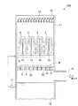
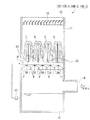
図1は、本実施の形態における排ガス処理塔10Aの構成を説明するための図である。
この図1に示すように、排ガス処理塔10Aは、塔本体11が例えば断面視矩形の筒状で、その底部は底板12によって閉塞され、上部には開口部13が形成されている。また、塔本体11の下部側面には、排ガスを塔本体11内に導入するための導入口14が開口して形成されている。
塔本体11内には、複数のノズル15を備えた配管16が設けられている。配管16には、塔本体11の底部に貯留された液がポンプ17で吸い上げられて供給されるようになっている。ノズル15は、この液を上方に向けて柱状に噴き上げるものであり、これら複数のノズル15は、互いに隣接するノズル15から噴き上げられる液柱Cに隙間が生じないように、適宜設定された間隔で配置されている。
Hereinafter, the present invention will be described in detail based on embodiments shown in the accompanying drawings.
[First embodiment]
FIG. 1 is a view for explaining the configuration of an exhaust
As shown in FIG. 1, the exhaust
A
本実施の形態において、排ガス処理塔10Aには、塔本体11の、ノズル15よりも下方で、かつ、導入口14よりも上方の部分に、液滴発生部材20が設けられている。
図2および図3に示すように、この液滴発生部材20は、グリッド等とも称されるもので、互いに直交するそれぞれ所定間隔で配置された縦板部(衝突部材)21と横板部(衝突部材)22とが互いに直交するよう組み合わせた形状を有しており、全体として格子状をなしている。縦板部21、横板部22は、それぞれその上面21a、22aが所定幅を有した平面とされている。また、縦板部21、横板部22は、所定の高さを有しており、これにより、互いに隣接する縦板部21、21と横板部22、22によって囲まれた部分に空間Sが形成されている。
In the present embodiment, the exhaust
As shown in FIGS. 2 and 3, the
上記構成を有した排ガス処理塔10Aにおいては、ノズル15から噴き上げられた液は、液柱Cを形成し、下方に落下する。そして、落下した液は、液滴発生部材20の上面21a、22aに衝突し、微細な液滴Mとなる。
このようにして発生した液滴Mは、通常であればそのまま浮遊しながら落下するわけであるが、液滴発生部材20に複数形成された空間S内において、縦板部21、横板部22の壁面との摩擦力によって、通常よりも長時間空間S内に浮遊した状態で保持される。なおこの現象は、流体の流速が、流れに沿った壁面近傍に近づくほど壁面との摩擦によって小さくなることと同様であり、容易に理解できることである。
そしてその後、液滴Mは、排ガス処理塔10A内を落下し、底部に貯留される。
In the exhaust
The droplet M generated in this way usually falls while floating as it is, but in the space S formed in the
Thereafter, the droplet M falls in the exhaust
一方、導入口14から略水平方向に導入された排ガスは、排ガス処理塔10A内で向きを変え、上方に向けて流れる。そして、第一の物質除去部として、ノズル15から上方に噴き上げられた液柱Cに接触することで、排ガス中の硫黄酸化物が液に吸収され、上部の開口部13から排出される。さらに、第二の物質除去部としての液滴発生部材20の部分においても、上面21a、22aに当たって発生し、空間Sに保持されて浮遊した微細な液滴Mと接触することで、排ガス中の硫黄酸化物が吸収されるようになっている。
なお、図1に示したように、排ガス処理塔10A内の上部にはエリミネータ18が設けられており、このエリミネータ18によって排ガス中に残存する微細な液滴Mが除去・回収される。
On the other hand, the exhaust gas introduced in the substantially horizontal direction from the
As shown in FIG. 1, an
上述したように、排ガス処理塔10Aにおいて、液滴発生部材20を備えることで、液柱Cだけでなく、液滴発生部材20の近傍に液滴Mを発生させて浮遊させることができる。これにより、排ガス処理塔10A内で従来は液が存在していなかった領域に液滴Mを存在させることができる。その結果、硫黄酸化物の除去性能を向上させることができる。
また、排ガスは、液柱Cや液滴Mと接触するときに抵抗力を受けるわけであるが、従来の液柱Cのみの場合と比較して、液滴Mが存在する分、全体としての抵抗力を増大させることができ、気液の接触効率を高めることができる。その結果、排ガスの流速を従来以上に上げたとしても、排ガスがそのまま吹き抜けてしまう限界流速を向上させることができる。したがって、排ガス処理塔10Aの脱硫性能を劇的に向上させることが可能となる。また、同等の性能を発揮すればよいのであれば、排ガスの流量を上げた分、排ガス処理塔10Aを従来よりも小型化することが可能となる。
As described above, the exhaust
In addition, the exhaust gas receives a resistance force when it comes into contact with the liquid column C and the droplet M, but compared to the case of the conventional liquid column C alone, the amount of the droplet M is present as a whole. The resistance force can be increased, and the contact efficiency of gas and liquid can be increased. As a result, even if the flow rate of exhaust gas is increased more than before, the critical flow rate at which exhaust gas blows through can be improved. Therefore, it is possible to dramatically improve the desulfurization performance of the exhaust
なお、上記実施の形態において、液滴発生部材20を、ノズル15の下方に配置したが、図4に示すように、ノズル15から発生する液柱Cの上方に配置する構成とすることも可能である。またもちろん、液滴発生部材20をノズル15の上方・下方の双方に設けることも可能である。
液柱Cの上方に液滴発生部材20を配置した場合、液柱Cから発生し、排ガスの流れによって上方に流される液滴Mを、液滴発生部材20の空間Sに保持することで、排ガス中の硫黄酸化物除去効果、排ガスの流れに対する抵抗力付与効果を発揮することができる。
In the above embodiment, the
When the
[第二の実施の形態]
次に、排ガス処理塔10Bに、スプレーノズル(ノズル)30を付加する場合の例を示す。なお、排ガス処理塔10Bの基本的な構成については上記第一の実施の形態と同様であるので、同一符号を付し、その説明を省略する。
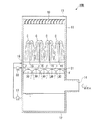
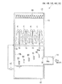
図5に示すように、排ガス処理塔10Bには、塔本体11の、ノズル15よりも下方で、かつ、導入口14よりも上方の部分に、複数のスプレーノズル30を備えた配管31が設けられている。
[Second Embodiment]
Next, an example in which a spray nozzle (nozzle) 30 is added to the exhaust
As shown in FIG. 5, the exhaust
この配管31には、塔本体11の底部からポンプ17で吸い上げた液をさらに昇圧させる昇圧ポンプ(ポンプ)33が接続されている。なお、ポンプ17と昇圧ポンプ33を2段に備えるのではなく、昇圧ポンプ33で塔本体11の底部から液を直接吸い上げる構成とすることもできるが、その場合、昇圧ポンプ33では、ポンプ17よりも高い圧力に液を昇圧させるのが好ましい。また、昇圧ポンプ33を設けず、ポンプ17のみを用いる構成とすることも可能である。
各スプレーノズル30からは、昇圧ポンプ33で昇圧された液を傘状(円錐状)に噴出し、全周にわたって連続する液膜Fを形成する。このとき、複数のスプレーノズル30は、互いに隣接するスプレーノズル30から傘状に噴出される液膜Fどうしが互いに重なり、塔本体11内に隙間が生じないように配置される。
Connected to the
From each
このような排ガス処理塔10Bでは、導入口14から略水平方向に導入された排ガスは、排ガス処理塔10B内で向きを変え、上方に向けて流れる。そして、第一の物質除去部としての、ノズル15から噴き上げられた液柱Cに接触することで、排ガス中の硫黄酸化物が液に吸収され、上部の開口部13から排出される。さらに、第二の物質除去部としての、スプレーノズル30から傘状に噴出する液膜Fに接触することで、排ガス中の硫黄酸化物が吸収されるようになっている。
In such an exhaust
上述したように、スプレーノズル30を備えることで、排ガス処理塔10B内で従来は液が存在していなかった、液柱Cとは異なる領域に液膜Fを存在させることができる。その結果、硫黄酸化物の除去性能を向上させることができる。
このとき、互いに隣接するスプレーノズル30から傘状に噴出される液膜Fどうしが互いに重なり、塔本体11内に隙間が生じないようにスプレーノズル30を配置することで、液柱Cによる液の存在が疎であった部分にも液を存在させることができ、これによって、排ガス処理塔10B内における硫黄酸化物の除去性能を均一化することができ、ガスの整流効果も得られる。
また、排ガスは、液柱Cや液膜Fと接触するときに抵抗力を受けるわけであるが、従来の液柱Cのみの場合と比較して、液膜Fが存在する分、気液の接触効率を高め、全体としての抵抗力を増大させることができる。その結果、排ガスの流速を従来以上に上げたとしても、排ガスがそのまま吹き抜けてしまう限界流速を向上させることができる。したがって、排ガス処理塔10Bの脱硫性能を劇的に向上させることが可能となる。また、同等の性能を発揮すればよいのであれば、排ガスの流量を上げた分、排ガス処理塔10Bを従来よりも小型化することが可能となる。
ところで、液柱Cに加え、スプレーノズル30では、昇圧ポンプ33によって昇圧した液を噴射している。液柱Cを用いず、スプレーノズル30を複数段備え、複数段の液膜Fのみで硫黄酸化物の除去を行う構成とすることも考えられるが、その場合、噴射する全ての液を昇圧ポンプ33で昇圧しなければならない。これに対し、上記のように、液柱Cに加え、スプレーノズル30から液膜Fを噴出することで、昇圧ポンプ33ではスプレーノズル30に供給する液のみを昇圧すれば良い。
As described above, by providing the
At this time, the liquid films F ejected in an umbrella shape from the
In addition, the exhaust gas receives a resistance force when it comes into contact with the liquid column C or the liquid film F. Compared to the case of the conventional liquid column C alone, the amount of gas-liquid is increased by the presence of the liquid film F. Contact efficiency can be increased and the overall resistance can be increased. As a result, even if the flow rate of exhaust gas is increased more than before, the critical flow rate at which exhaust gas blows through can be improved. Therefore, it is possible to dramatically improve the desulfurization performance of the exhaust
By the way, in addition to the liquid column C, the
なお、上記実施の形態において、スプレーノズル30を、ノズル15の下方に配置したが、図6に示すように、ノズル15から発生する液柱Cの上方に配置する構成とすることも可能である。またもちろん、スプレーノズル30をノズル15の上方・下方の双方に設けることも可能である。
In the above embodiment, the
[第三の実施の形態]
次に、排ガス処理塔10Cに、液滴発生部材20とスプレーノズル30の双方を組み合わせて備える場合の例を示す。なお、排ガス処理塔10Cの基本的な構成については上記第一、第二の実施の形態と同様であるので、同一符号を付し、その説明を省略する。
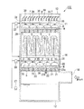
図7に示すように、排ガス処理塔10Cには、塔本体11の、ノズル15よりも下方で、かつ、導入口14よりも上方の部分に、複数のスプレーノズル30を備えた配管31が設けられている。さらに、排ガス処理塔10Cには、スプレーノズル30の下方で、かつ、導入口14よりも上方の部分に、液滴発生部材20が設けられている。
[Third embodiment]
Next, an example in which the exhaust gas treatment tower 10C is provided with a combination of both the
As shown in FIG. 7, the exhaust
このような構成において、ノズル15から噴き上げられた液は、液柱Cを形成し、下方に落下する。そして、落下した液は、液滴発生部材20の上面21a、22aに衝突し、微細な液滴Mとなる。
また、各スプレーノズル30からは、昇圧ポンプ33で昇圧された液を、傘状、円錐状に噴出し、液膜Fを形成する。さらに、液膜Fを形成した液は落下し、下方の液滴発生部材20の上面21a、22aに衝突して微細な液滴Mとなる。
このようにして発生した液滴Mは、液滴発生部材20に複数形成された空間S内において、浮遊した状態で保持される。
そしてその後、液滴Mは、排ガス処理塔10C内を落下し、底部に貯留される。
In such a configuration, the liquid spouted from the
Further, from each
The droplets M generated in this way are held in a floating state in a plurality of spaces S formed in the
Thereafter, the droplet M falls in the exhaust gas treatment tower 10C and is stored at the bottom.
このような排ガス処理塔10Cでは、導入口14から略水平方向に導入された排ガスは、排ガス処理塔10C内で向きを変え、上方に向けて流れる。そして、第二の物質除去部としての液滴発生部材20の部分において空間Sに保持されて浮遊した微細な液滴M、同じく第二の物質除去部としてのスプレーノズル30から傘状に噴出する液膜F、さらに第一の物質除去部としてのノズル15から噴き上げられた液柱Cに接触することで、排ガス中の硫黄酸化物が液に吸収され、上部の開口部13から排出される。
In such an exhaust gas treatment tower 10C, the exhaust gas introduced in the substantially horizontal direction from the
上述したように、液滴発生部材20と、スプレーノズル30を備えることで、排ガス処理塔10C内で従来は液が存在していなかった領域に液滴Mや液膜Fを存在させることができる。その結果、硫黄酸化物の除去性能を向上させることができる。
また、排ガスは、液柱C、液膜F、液滴Mと接触するときに抵抗力を受けるわけであるが、従来の液柱Cのみの場合と比較して、液膜F、液滴Mが存在する分、気液の接触効率を高め、全体としての抵抗力を増大させることができる。その結果、排ガスの流速を従来以上に上げたとしても、排ガスがそのまま吹き抜けてしまう限界流速を向上させることができる。したがって、排ガス処理塔10Cの脱硫性能を劇的に向上させることが可能となる。また、同等の性能を発揮すればよいのであれば、排ガスの流量を上げた分、排ガス処理塔10Cを従来よりも小型化することが可能となる。
ところで、液滴発生部材20のみを備えた第一の実施の形態、スプレーノズル30のみを備えた第二の実施の形態に比較し、液滴発生部材20とスプレーノズル30の双方を備えた本実施の形態の構成では、スプレーノズル30からの液膜Fの液が液滴発生部材20の上面21a、22aに衝突することで液滴Mを発生するので、液滴Mの発生量が単なる組み合わせ以上のものとなる。したがって、本実施の形態における排ガス処理塔10Cにおける上記したような効果は、一層顕著なものとなる。
As described above, by providing the
In addition, the exhaust gas receives a resistance force when it comes into contact with the liquid column C, the liquid film F, and the droplet M, but compared with the case of the conventional liquid column C alone, the liquid film F, the droplet M. As a result, the gas-liquid contact efficiency can be increased and the overall resistance can be increased. As a result, even if the flow rate of exhaust gas is increased more than before, the critical flow rate at which exhaust gas blows through can be improved. Therefore, it is possible to dramatically improve the desulfurization performance of the exhaust gas treatment tower 10C. In addition, if the equivalent performance is to be exhibited, the exhaust gas treatment tower 10C can be made smaller than before in accordance with the increased flow rate of the exhaust gas.
By the way, as compared with the first embodiment having only the
なお、上記実施の形態において、液滴発生部材20およびスプレーノズル30を、ノズル15の下方に配置したが、図8に示すように、ノズル15から発生する液柱Cの上方にも配置する構成とすることも可能である。またもちろん、液滴発生部材20およびスプレーノズル30をノズル15の下方には配置せず、液柱Cの上方にのみ設けることも可能である。
In the above embodiment, the
ここで、上記第一〜第三の実施の形態で示した排ガス処理塔10の性能を評価する試験を行ったので、その結果を以下に示す。
図1に示した第一の実施の形態における排ガス処理塔10Aと、図5に示した第二の実施の形態における排ガス処理塔10B、図7に示した第三の実施の形態における排ガス処理塔10Cの他、比較のため、図21に示した従来の排ガス処理塔1において、それぞれ、塔入口(導入口14)におけるSO2濃度を2700ppmDとし、脱硫のための液は、NH3の濃度を270mmol/l、炭酸カルシウムの濃度を115mmol/lとし、ガス流速と、排ガス処理塔10の出口(開口部13)におけるSO2の濃度との関係を調べた。このとき、従来の排ガス処理塔1、液滴発生部材20のみを備えた第一の実施の形態における排ガス処理塔10Aでは、液の循環流量を304m3/(m2×h)とし、スプレーノズル30のみを備えた第二の実施の形態における排ガス処理塔10B、液滴発生部材20とスプレーノズル30の双方を備えた第三の実施の形態における排ガス処理塔10Cでは、液柱Cを発生させるための液の循環流量を274m3/(m2×h)、スプレーノズル30に送り込む液の流量を59m3/(m2×h)とした。
Here, since the test which evaluates the performance of the exhaust
Exhaust
その結果、図9に示すように、従来の排ガス処理塔1に比較し、排ガス処理塔10A、10B、10Cは、出口におけるSO2の濃度が高まる時点での流速(これを限界流速と称する)が大幅に向上している。特に、液滴発生部材20のみを備えた第一の実施の形態における排ガス処理塔10A、スプレーノズル30のみを備えた第二の実施の形態における排ガス処理塔10Bに比較し、液滴発生部材20とスプレーノズル30の双方を備えた第三の実施の形態における排ガス処理塔10Cでは、限界流速が高くなっている。
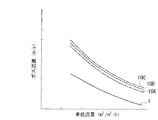
また、液柱Cの単位断面積当りの降液量(以下、これを単位流量と称する)と、ガス流速(限界流速)との関係を調べた。
その結果、図10に示すように、液の単位流量が同条件であれば、従来の排ガス処理塔1に比較し、排ガス処理塔10A、10B、10Cは、限界流速が大幅に向上していることがわかる。
As a result, as shown in FIG. 9, compared with the conventional exhaust
Further, the relationship between the amount of liquid fall per unit cross-sectional area of the liquid column C (hereinafter referred to as unit flow rate) and the gas flow rate (limit flow rate) was examined.
As a result, as shown in FIG. 10, if the unit flow rate of the liquid is the same, the exhaust gas treatment towers 10A, 10B, and 10C have significantly improved critical flow rates compared to the conventional exhaust
さらに、液柱Cの単位流量と、脱硫率との関係を調べた。
その結果、図11に示すように、液の単位流量が同条件であれば、従来の排ガス処理塔1に比較し、排ガス処理塔10A、10B、10Cは、脱硫率が大幅に向上しており、同一流量では、吸収容量係数が、10%(排ガス処理塔10Bの場合)〜30%(排ガス処理塔10A、10Cの場合)向上している。これにより、脱硫性能が、従来の排ガス処理塔1に比較し、1.1〜1.3倍に向上していることがわかる。
Furthermore, the relationship between the unit flow rate of the liquid column C and the desulfurization rate was examined.
As a result, as shown in FIG. 11, if the unit flow rate of the liquid is the same, the desulfurization rate of the exhaust gas treatment towers 10A, 10B, and 10C is greatly improved as compared with the conventional exhaust
[第四の実施の形態]
次に、排ガス処理塔10Dに、前記第二の実施の形態と同様、スプレーノズル(ノズル)30を付加する場合の例を示す。なお、排ガス処理塔10Dの基本的な構成については上記第一の実施の形態と同様であるので、同一符号を付し、その説明を省略する。
図12に示すように、排ガス処理塔10Dには、塔本体11の、ノズル15よりも下方で、かつ、導入口14よりも上方の部分に、複数のスプレーノズル30が設けられている。
ここで、前記第二の実施の形態に示した排ガス処理塔10Bとの構成の違いは、排ガス処理塔10Bでは、複数のスプレーノズル30を、ノズル15が設けられた配管16とは別の、配管31に設けるようにしたが、本実施の形態の排ガス処理塔10Dでは、複数のスプレーノズル30を、ノズル15が設けられた配管16に設ける点にある。
[Fourth embodiment]
Next, an example in which a spray nozzle (nozzle) 30 is added to the exhaust
As shown in FIG. 12, the exhaust
Here, the difference from the configuration of the exhaust
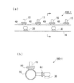
図13〜図15に、配管16にスプレーノズル30を取り付ける構造の詳細例を複数示す。
図13に示す排ガス処理塔10D−1では、配管16に、各ノズル15を取り付けるためのフランジ部材40が、上方に突出するように設けられている。そして、この配管16には、略水平方向に突出するフランジ部材41が設けられ、このフランジ部材41に、下方に向けて液を傘状に噴出して液膜Fを形成するスプレーノズル30が取り付けられている。ここで、フランジ部材41は、例えば2〜3個のノズル15に対し、1個が位置するよう、適宜配置することができる。
既設の排ガス処理塔にスプレーノズル30を追設して排ガス処理塔10D−1を実現する場合は、配管16にフランジ部材41を設け、このフランジ部材41にスプレーノズル30を取り付ける。
FIGS. 13 to 15 show a plurality of detailed examples of the structure in which the
In the exhaust
When the
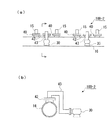
図14に示す排ガス処理塔10D−2では、各ノズル15を取り付けるためのフランジ部材40が上方に突出するように設けられた配管16に、同じく上方に突出するフランジ部材42が設けられている。そして、このフランジ部材42に延長管43が取り付けられ、この延長管43の先端部にスプレーノズル30が設けられている。延長管43は、スプレーノズル30から液を下方に向けて噴出し、しかも噴出する液が配管16と干渉しないようにスプレーノズル30の姿勢・位置を保持するべく、屈曲して取り回されている。
ここで、フランジ部材41は、例えば2個のノズル15に対し、1個が位置するよう、互いに隣接する2個1組のノズル15の中間部に配置することができる。
既設の排ガス処理塔にスプレーノズル30を追設して排ガス処理塔10D−2を実現する場合は、配管16にフランジ部材42を設け、このフランジ部材42に、延長管43およびスプレーノズル30を取り付ける。
In the exhaust
Here, the
When the
図15に示す排ガス処理塔10D−3では、配管16に設けられた、各ノズル15を取り付けるため上方に突出するように設けられたフランジ部材40に、取り出し管45を介し、スプレーノズル30が設けられている。
取り出し管45は、フランジ部材40と同等の内径を有し、上下にフランジを有してフランジ部材40とノズル15との間に介在する本体部45aと、この本体部45aから側方に分岐し、その先端部にスプレーノズル30が取り付けられる分岐部45bとから構成されている。ここで、分岐部45bは、スプレーノズル30から液を下方に向けて噴出し、しかも噴出する液が配管16と干渉しないようにスプレーノズル30の姿勢・位置を保持するべく、屈曲して取り回されている。
ここで、このような取り出し管45は、例えば2個のノズル15あたり1個が位置するよう、配置されている。
既設の排ガス処理塔にスプレーノズル30を追設して排ガス処理塔10D−3を実現する場合は、既設のノズル15をフランジ部材40から取り外した後、取り出し管45を取り付け、この取り出し管45にノズル15を再装着する。そして、取り出し管45の先端部にスプレーノズル30を取り付ける。
In the exhaust
The take-out
Here, for example, one such take-out
In the case of realizing the exhaust
図13〜図15に示したような構成においては、ポンプ17によって加圧された液は、配管16を通り、ノズル15とスプレーノズル30とから噴出され、液柱Cおよび液膜Fを形成する。このようにして、上記第二の実施の形態で示した排ガス処理塔10Bと同様、スプレーノズル30を備えることで、硫黄酸化物の除去性能の向上、脱硫性能の向上等が可能となる。
さらに、上記第一〜第三の実施の形態で示した排ガス処理塔10A、10B、10Cでは、液滴発生部材20や、スプレーノズル30を取り付けるための配管31を設けているため、その分、排ガス処理塔10A、10B、10Cにおけるガス流路の開口率が減少し、ガスの圧力損失が大きくなる。
これに対し、本実施の形態の排ガス処理塔10D(10D−1、10D−2、10D−3)では、液柱Cを発生するノズル15が設けられた配管16に、スプレーノズル30を設けるようにしたので、開口率の減少を抑制し、圧力損失を小さくすることが可能となっている。
In the configuration shown in FIGS. 13 to 15, the liquid pressurized by the
Furthermore, in the exhaust gas treatment towers 10A, 10B, and 10C shown in the first to third embodiments, since the
In contrast, in the exhaust
ここで、本実施の形態における排ガス処理塔10D−1、10D−2、10D−3と、図5に示した第二の実施の形態における排ガス処理塔10Bとを比較したのでその結果を示す。
排ガス処理塔10B、排ガス処理塔10D−1、10D−2、10D−3において、それぞれ、塔内温度を30℃、ガス流速を2.5〜4.5m/s、塔入口(導入口14)におけるSO2濃度を500ppmD、脱硫のための液は、炭酸カルシウムの濃度を160mmol/l、ノズル15からの液柱Cの噴霧高さを1〜5m、液の循環流量を150〜600m3/(m2×h)とした。
そのときの、単位循環流量と脱硫率との関係、ガス流速に対する圧力損失との関係を調べた。
Here, the exhaust gas treatment towers 10D-1, 10D-2, 10D-3 in the present embodiment are compared with the exhaust
In the exhaust
At that time, the relationship between the unit circulation flow rate and the desulfurization rate and the relationship with the pressure loss with respect to the gas flow rate were investigated.
図16および図17は、その結果を示すものである。
図16に示すように、本実施の形態における排ガス処理塔10D−1、10D−2、10D−3と、図5に示した第二の実施の形態における排ガス処理塔10Bとでは、ほぼ同等の脱硫性能が得られていることがわかる。そして、図17に示すように、本実施の形態における排ガス処理塔10D−1、10D−2、10D−3と、図5に示した第二の実施の形態における排ガス処理塔10Bとでは、本実施の形態における排ガス処理塔10D−1、10D−2、10D−3の方が圧力損失が大幅に低減されていることがわかる。つまり、本実施の形態における排ガス処理塔10D−1、10D−2、10D−3では、第二の実施の形態における排ガス処理塔10Bに比較し、脱硫率を維持したまま、圧力損失を大幅に低減することができるのである。
16 and 17 show the results.
As shown in FIG. 16, the exhaust gas treatment towers 10D-1, 10D-2, 10D-3 in the present embodiment and the exhaust
ところで、液に含まれるSO2成分により、液が直接当たらない部分には、スケールが付着しやすい。例えば、上記第一〜第三の実施の形態で示した排ガス処理塔10A、10B、10Cでは、液滴発生部材20や、スプレーノズル30を取り付けるための配管31を設けているため、液が直接当たらない部分の表面積が、排ガス処理塔10D(10D−1、10D−2、10D−3)に比較して大きく、スケールが付着しやすい。付着したスケールが落下すると、その下方に位置するノズルや配管等を損傷する可能性がある。本実施の形態の排ガス処理塔10D(10D−1、10D−2、10D−3)では、配管16にスプレーノズル30を設けることにより、スケールが付着する可能性のある箇所を最小限に抑えることができ、損傷の発生も抑制することができる。
By the way, due to the SO 2 component contained in the liquid, the scale is likely to adhere to a portion where the liquid does not directly hit. For example, in the exhaust gas treatment towers 10A, 10B, and 10C shown in the first to third embodiments, the liquid droplets directly flow because the
また、既設の排ガス処理塔にスプレーノズル30を追設して排ガス処理塔10D−1、10D−2、10D−3を実現する場合、既設の配管16に、フランジ部材41、延長管43、取り出し管45を取り付け、これにノズル15を装着すればよい。そして、取り出し管45の先端部にスプレーノズル30を取り付ける。液滴発生部材20や、配管31を設けなければならず、大掛かりな作業が必要となる上記第一〜第三の実施の形態で示した排ガス処理塔10A、10B、10Cに比較し、部品点数が少なく、その設置も容易で低コスト化が図れる。
特に、図15に示した排ガス処理塔10D−3の場合、既設のノズル15を取り付けるためのフランジ部材40に取り出し管45を取り付けるだけでよく、フランジ部材41や延長管43の取り付けに溶接等が必要となる排ガス処理塔10D−1、10D−2に比較し、作業も容易で、低コストで上記効果を得ることができる。
図14に示した排ガス処理塔10D−2においても、同様に、既設のノズル15を取り付けるためのフランジ部材40に延長管43およびスプレーノズル30を取り付けることも可能ではあるが、その場合、液柱Cを形成するノズル15の数が減少してしまうため好ましくない。
Further, when the exhaust gas treatment towers 10D-1, 10D-2, and 10D-3 are realized by adding the
In particular, in the case of the exhaust
Similarly, in the exhaust
なお、上記第四の実施の形態において、排ガス処理塔10D−1、10D−2のフランジ部材41、延長管43の設置箇所(数)等をノズル15の設置位置との関係で決める例を挙げたが、例示したものに限るものではない。特に既設の排ガス処理塔を改造するのではなく、排ガス処理塔10D−1、10D−2を新設する場合には、スプレーノズル30の位置・数が最適化されるような位置に、フランジ部材41、延長管43を設ければ良い。
In the fourth embodiment, an example is given in which the installation location (number) of the
ところで、上記各実施の形態で示した排ガス処理塔10A、10B、10C、10D(以下、特に区別する必要が無い場合には単に排ガス処理塔10と称する)には、以下に示すような構成を組み合わせるのが有効である。
図18に示すように、排ガス処理塔10の導入口14の部分において、排ガス処理塔10の鉛直内壁面10aと、導入口14の内部上面14aとの間に、所定角度に傾斜する傾斜面48を形成する。この傾斜面48により、導入口14の断面積は、排ガス処理塔10の鉛直内壁面10aに近づくにしたがい、上方に漸次拡大するようになっている。
このような傾斜面48を形成することで、導入口14から導入された排ガスの流れが上方に向きを変える部分で、内周側の流速を高めることができ、これによって排ガス処理塔10の塔本体11内における偏流を緩和することができる。
このような傾斜面48を上記各実施の形態に組み合わせることで、排ガスの流れを均一化することができ、上記効果を一層顕著なものとすることができる。
By the way, the exhaust gas treatment towers 10A, 10B, 10C, and 10D (hereinafter simply referred to as the exhaust
As shown in FIG. 18, in the
By forming such an
By combining such an
図19は、排ガス処理塔10の塔本体11内において、導入口14の正面部分に、導入口14から送り込まれる排ガスの流れと略直交する方向の整流板50を複数枚設ける。このとき、複数枚の整流板50は、導入口14に近い側が上方に位置するよう、高さを異ならせて配置する。また、導入口14の内部上面14aと、鉛直内壁面10aとの交差部分から、斜め下方に延出するフラップ51を設ける。
このような整流板50およびフラップ51により、導入口14から導入された排ガスの流れが上方に向きを変える部分で、排ガスはフラップ51により各整流板50に導かれ、各整流板50に当たって向きを変える。この整流板50が無い場合には、排ガスの流速が速ければ速いほど、排ガスは導入口14の正面の鉛直内壁面10bに向かって直進し、鉛直内壁面10bに当たって向きを変える成分が多くなる。これに対し、上記のように排ガスの流れを各整流板50に当てて向きを変えさせることで、排ガス処理塔10の塔本体11内における偏流を緩和することができるのである。このような整流板50を上記各実施の形態に組み合わせることでも、排ガスの流れを均一化することができ、上記効果を一層顕著なものとすることができる。
In FIG. 19, in the tower
The flow of the exhaust gas introduced from the
ここで、上記の傾斜面48、整流板50を設けた場合の効果を実証するための試験を行ったので、その結果を以下に示す。
図18に示した傾斜面48を設けた排ガス処理塔10と、図19に示した整流板50を設けた排ガス処理塔10の他、比較のため、図21に示した従来の排ガス処理塔1において、前記と同様の条件で試験を行い、液の単位流量と脱硫率との関係(図20(a)参照)、ガス流速と脱硫率との関係(図20(b)参照)を調べた。
その結果、図20(a)、(b)に示すように、液の単位流量あるいはガス流速が同条件であれば、従来の排ガス処理塔1に比較し、傾斜面48、整流板50を設けた排ガス処理塔10は、脱硫率が向上していることがわかる。
このようにして、傾斜面48や整流板50を設けることで、排ガス処理塔10A、10B、10C、10Dの性能をさらに向上させることができる。
Here, since the test for demonstrating the effect at the time of providing the said
In addition to the exhaust
As a result, as shown in FIGS. 20A and 20B, if the unit flow rate of the liquid or the gas flow rate is the same, an
Thus, by providing the
これ以外にも、本発明の主旨を逸脱しない限り、上記各実施の形態で挙げた構成を取捨選択したり、他の構成に適宜変更することが可能である。 Other than this, as long as the gist of the present invention is not deviated, the configurations described in the above embodiments can be selected or changed to other configurations as appropriate.
10、10A、10B、10C、10D…排ガス処理塔、11…塔本体、14…導入口、15…ノズル、20…液滴発生部材、21…縦板部(衝突部材)、22…横板部(衝突部材)、30…スプレーノズル(ノズル)、33…昇圧ポンプ(ポンプ)、41、42…フランジ部材、43…延長管、45…取り出し管、48…傾斜面、50…整流板、C…液柱、F…液膜、M…液滴、S…空間
DESCRIPTION OF
Claims (7)
前記塔本体内にて、下方から上方に柱状に液を噴出することで液柱を発生させ、前記排ガスに前記液柱が接触することで当該排ガスに含まれる物質を除去する第一の物質除去部と、
前記第一の物質除去部で発生する前記液柱とは異なる領域に設けられ、前記排ガスに液を接触させることで当該排ガスに含まれる物質を除去する第二の物質除去部と、
を備えることを特徴とする排ガス処理塔。 A tower main body for discharging the exhaust gas introduced from below, upward;
In the tower body, a liquid substance is generated by jetting a liquid in a column shape from below to above, and a first substance removal that removes a substance contained in the exhaust gas by contacting the liquid column with the exhaust gas. And
A second substance removing unit that is provided in a region different from the liquid column generated in the first substance removing unit, and removes a substance contained in the exhaust gas by bringing the liquid into contact with the exhaust gas;
An exhaust gas treatment tower comprising:
前記ノズルは、当該ノズルから発生する液膜が、隣接する他の前記ノズルからの液膜と隙間なく重なるよう配置されていることを特徴とする請求項1または2に記載の排ガス処理塔。 As the second substance removing unit, a plurality of nozzles for generating a liquid film by ejecting liquid in an umbrella shape are provided,
3. The exhaust gas treatment tower according to claim 1, wherein the nozzle is disposed such that a liquid film generated from the nozzle overlaps with a liquid film from another adjacent nozzle without any gap.
Priority Applications (9)
| Application Number | Priority Date | Filing Date | Title |
|---|---|---|---|
| JP2003356562A JP4088578B2 (en) | 2003-07-11 | 2003-10-16 | Exhaust gas treatment tower |
| US10/875,513 US20050046052A1 (en) | 2003-07-11 | 2004-06-25 | Exhaust gas treating tower |
| TW093119847A TWI236928B (en) | 2003-07-11 | 2004-06-30 | Exhaust gas treating tower |
| ES04103283T ES2389077T3 (en) | 2003-07-11 | 2004-07-09 | Exhaust gas treatment tower |
| EP04103283A EP1510242B1 (en) | 2003-07-11 | 2004-07-09 | Exhaust gas treating tower |
| TR2004/01691A TR200401691A2 (en) | 2003-07-11 | 2004-07-12 | Exhaust gas cleaning tower |
| KR1020040060457A KR100583930B1 (en) | 2003-10-16 | 2004-07-30 | Exhaust gas treating tower |
| CNB200410075225XA CN1308057C (en) | 2003-10-16 | 2004-09-13 | Exhaust gas treating tower |
| US11/783,320 US7326286B2 (en) | 2003-07-11 | 2007-04-09 | Exhaust gas treating tower |
Applications Claiming Priority (2)
| Application Number | Priority Date | Filing Date | Title |
|---|---|---|---|
| JP2003196068 | 2003-07-11 | ||
| JP2003356562A JP4088578B2 (en) | 2003-07-11 | 2003-10-16 | Exhaust gas treatment tower |
Publications (2)
| Publication Number | Publication Date |
|---|---|
| JP2005046830A true JP2005046830A (en) | 2005-02-24 |
| JP4088578B2 JP4088578B2 (en) | 2008-05-21 |
Family
ID=34277280
Family Applications (1)
| Application Number | Title | Priority Date | Filing Date |
|---|---|---|---|
| JP2003356562A Expired - Lifetime JP4088578B2 (en) | 2003-07-11 | 2003-10-16 | Exhaust gas treatment tower |
Country Status (1)
| Country | Link |
|---|---|
| JP (1) | JP4088578B2 (en) |
Cited By (5)
| Publication number | Priority date | Publication date | Assignee | Title |
|---|---|---|---|---|
| WO2015115276A1 (en) * | 2014-01-31 | 2015-08-06 | 三菱重工業株式会社 | Gas-liquid contactor and co2-recovering apparatus provided therewith |
| CN108579396A (en) * | 2018-07-10 | 2018-09-28 | 华润电力焦作有限公司 | A kind of device and method of flue gas desulfurization |
| WO2020149228A1 (en) * | 2019-01-18 | 2020-07-23 | 三菱日立パワーシステムズ株式会社 | Method for modifying liquid column-type absorption tower and liquid column-type absorption tower |
| CN111729339A (en) * | 2020-07-30 | 2020-10-02 | 天津普莱化工技术有限公司 | Jet unit for tower plate, large liquid holdup three-dimensional jet tower plate and gas-liquid mass transfer method thereof |
| JPWO2021200942A1 (en) * | 2020-03-31 | 2021-10-07 |
-
2003
- 2003-10-16 JP JP2003356562A patent/JP4088578B2/en not_active Expired - Lifetime
Cited By (11)
| Publication number | Priority date | Publication date | Assignee | Title |
|---|---|---|---|---|
| WO2015115276A1 (en) * | 2014-01-31 | 2015-08-06 | 三菱重工業株式会社 | Gas-liquid contactor and co2-recovering apparatus provided therewith |
| JP2015144980A (en) * | 2014-01-31 | 2015-08-13 | 三菱重工業株式会社 | Gas-liquid contact device and CO2 recovery device provided with the same |
| US10065149B2 (en) | 2014-01-31 | 2018-09-04 | Mitsubishi Heavy Industries Engineering Ltd. | Gas-liquid contactor and CO2-recovering apparatus provided therewith |
| CN108579396A (en) * | 2018-07-10 | 2018-09-28 | 华润电力焦作有限公司 | A kind of device and method of flue gas desulfurization |
| WO2020149228A1 (en) * | 2019-01-18 | 2020-07-23 | 三菱日立パワーシステムズ株式会社 | Method for modifying liquid column-type absorption tower and liquid column-type absorption tower |
| JP2020114582A (en) * | 2019-01-18 | 2020-07-30 | 三菱日立パワーシステムズ株式会社 | Remodeling method of liquid column type absorption column and liquid column type absorption column |
| JP7280699B2 (en) | 2019-01-18 | 2023-05-24 | 三菱重工業株式会社 | Modification method of liquid column type absorption tower and liquid column type absorption tower |
| JPWO2021200942A1 (en) * | 2020-03-31 | 2021-10-07 | ||
| WO2021200942A1 (en) * | 2020-03-31 | 2021-10-07 | 三菱パワー株式会社 | Absorption tower of desulphurization device |
| JP7524308B2 (en) | 2020-03-31 | 2024-07-29 | 三菱重工業株式会社 | Absorption tower of desulfurization equipment |
| CN111729339A (en) * | 2020-07-30 | 2020-10-02 | 天津普莱化工技术有限公司 | Jet unit for tower plate, large liquid holdup three-dimensional jet tower plate and gas-liquid mass transfer method thereof |
Also Published As
| Publication number | Publication date |
|---|---|
| JP4088578B2 (en) | 2008-05-21 |
Similar Documents
| Publication | Publication Date | Title |
|---|---|---|
| KR100246597B1 (en) | Horizontal wet scrubbing apparatus and method for removing sulfur dioxide from a gaseous stream | |
| TWI236928B (en) | Exhaust gas treating tower | |
| JP2003001045A (en) | Wet gas processing apparatus | |
| JP2007275715A (en) | Wet-type flue gas desulfurization device | |
| CN108367234A (en) | Flue gas desulfurization equipment | |
| JPH119956A (en) | Absorption tower of wet flue gas desulfurizer | |
| JP2005046830A (en) | Exhaust gas treating column | |
| JP2002136835A (en) | Two-chamber type wet flue gas desulfurization apparatus | |
| JP2015042389A (en) | Exhaust gas desulfurizer | |
| KR100583930B1 (en) | Exhaust gas treating tower | |
| JP7094117B2 (en) | Water treatment tank and desulfurization equipment | |
| JP2008200619A (en) | Exhaust gas desulfurizer | |
| JP4905926B2 (en) | Two-chamber wet flue gas desulfurization system | |
| WO2014196458A1 (en) | Device for desulfurization with seawater and system for desulfurization with seawater | |
| JP2004237258A (en) | Wet type flue gas desulfurization equipment | |
| JP2006122862A (en) | Apparatus for treating exhaust gas | |
| US20090151563A1 (en) | Extraction device | |
| RU2356843C1 (en) | Desorption plant | |
| CN104056540A (en) | Turbulent washing flue gas dust removal desulfurizer | |
| JP3519497B2 (en) | Wet flue gas desulfurization equipment | |
| TWI802860B (en) | Absorption tower of desulfurization unit | |
| JP2016087539A (en) | Method for exhaust gas desulfurization and removing soot and dust | |
| JP3338209B2 (en) | Absorption tower of wet flue gas desulfurization unit | |
| JPH0938447A (en) | Liquid absorbent dispersing equipment and flue gas desulfurizer | |
| JP2016055244A (en) | Flue gas treatment apparatus |
Legal Events
| Date | Code | Title | Description |
|---|---|---|---|
| A621 | Written request for application examination |
Free format text: JAPANESE INTERMEDIATE CODE: A621 Effective date: 20060530 |
|
| A977 | Report on retrieval |
Free format text: JAPANESE INTERMEDIATE CODE: A971007 Effective date: 20070628 |
|
| A131 | Notification of reasons for refusal |
Free format text: JAPANESE INTERMEDIATE CODE: A131 Effective date: 20070718 |
|
| A521 | Request for written amendment filed |
Free format text: JAPANESE INTERMEDIATE CODE: A523 Effective date: 20070918 |
|
| A131 | Notification of reasons for refusal |
Free format text: JAPANESE INTERMEDIATE CODE: A131 Effective date: 20071017 |
|
| A521 | Request for written amendment filed |
Free format text: JAPANESE INTERMEDIATE CODE: A523 Effective date: 20071214 |
|
| TRDD | Decision of grant or rejection written | ||
| A01 | Written decision to grant a patent or to grant a registration (utility model) |
Free format text: JAPANESE INTERMEDIATE CODE: A01 Effective date: 20080206 |
|
| A61 | First payment of annual fees (during grant procedure) |
Free format text: JAPANESE INTERMEDIATE CODE: A61 Effective date: 20080225 |
|
| FPAY | Renewal fee payment (event date is renewal date of database) |
Free format text: PAYMENT UNTIL: 20110228 Year of fee payment: 3 |
|
| R151 | Written notification of patent or utility model registration |
Ref document number: 4088578 Country of ref document: JP Free format text: JAPANESE INTERMEDIATE CODE: R151 |
|
| FPAY | Renewal fee payment (event date is renewal date of database) |
Free format text: PAYMENT UNTIL: 20110228 Year of fee payment: 3 |
|
| FPAY | Renewal fee payment (event date is renewal date of database) |
Free format text: PAYMENT UNTIL: 20120229 Year of fee payment: 4 |
|
| FPAY | Renewal fee payment (event date is renewal date of database) |
Free format text: PAYMENT UNTIL: 20120229 Year of fee payment: 4 |
|
| FPAY | Renewal fee payment (event date is renewal date of database) |
Free format text: PAYMENT UNTIL: 20130228 Year of fee payment: 5 |
|
| FPAY | Renewal fee payment (event date is renewal date of database) |
Free format text: PAYMENT UNTIL: 20140228 Year of fee payment: 6 |
|
| S111 | Request for change of ownership or part of ownership |
Free format text: JAPANESE INTERMEDIATE CODE: R313111 |
|
| R350 | Written notification of registration of transfer |
Free format text: JAPANESE INTERMEDIATE CODE: R350 |
|
| EXPY | Cancellation because of completion of term |