JP2005106900A - Projection imaging optical system - Google Patents
Projection imaging optical system Download PDFInfo
- Publication number
- JP2005106900A JP2005106900A JP2003336903A JP2003336903A JP2005106900A JP 2005106900 A JP2005106900 A JP 2005106900A JP 2003336903 A JP2003336903 A JP 2003336903A JP 2003336903 A JP2003336903 A JP 2003336903A JP 2005106900 A JP2005106900 A JP 2005106900A
- Authority
- JP
- Japan
- Prior art keywords
- optical system
- projection
- imaging optical
- focus adjustment
- projection imaging
- Prior art date
- Legal status (The legal status is an assumption and is not a legal conclusion. Google has not performed a legal analysis and makes no representation as to the accuracy of the status listed.)
- Withdrawn
Links
Images

Landscapes
- Liquid Crystal (AREA)
- Projection Apparatus (AREA)
- Lenses (AREA)
Abstract
【課題】 自由曲面反射面を複数組合わせて構成した投射結像光学系において、投射スクリーンまでの距離に応じてフォーカス調整を光学系の部分調整により実施することが可能な投射光学系を提供すること。
【解決手段】 最終面を含む2面以上の部分系をフォーカス調整群として投射光軸に平行に可動な構成とする。このフォーカス調整群は入射光軸と射出光軸が平行で、フォーカス調整により投射画像の中心は動かないように構成する。
【選択図】 図1
PROBLEM TO BE SOLVED: To provide a projection optical system capable of performing focus adjustment by partial adjustment of an optical system in a projection imaging optical system configured by combining a plurality of free curved reflecting surfaces. about.
A partial system including two or more surfaces including a final surface is configured to be movable in parallel with a projection optical axis as a focus adjustment group. This focus adjustment group is configured such that the incident optical axis and the outgoing optical axis are parallel, and the center of the projected image does not move by the focus adjustment.
[Selection] Figure 1
Description
本発明は、投射型表示装置に用いる投射結像光学系に関し、例えば液晶表示素子(液晶パネル)や米テキサスインスツルメンツ社のデジタルマイクロミラーデバイス等の画像表示装置によって光変調された光束を投射スクリーン又は壁等に投射し、画像情報を形成する液晶プロジェクター(プロジェクション)等の光学機器に好適なものである。 The present invention relates to a projection imaging optical system for use in a projection display device, for example, a projection screen or a light beam modulated by an image display device such as a liquid crystal display element (liquid crystal panel) or a digital micromirror device of Texas Instruments, Inc. It is suitable for an optical apparatus such as a liquid crystal projector (projection) that projects on a wall or the like and forms image information.
従来から、液晶パネル等の画像表示装置を光源からの光束により照明し、画像表示装置で光変調された透過光又は反射光を用いて投影レンズにより、投射スクリーン又は壁に拡大投射して画像形成するプロジェクターが種々提案されている。 Conventionally, an image display device such as a liquid crystal panel is illuminated with a light beam from a light source, and an image is formed by projecting on a projection screen or a wall with a projection lens using transmitted light or reflected light light-modulated by the image display device. Various projectors have been proposed.
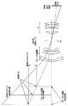
また、再公表特許の国際公開番号WO97/01787号公報には、複数の反射面を用いて斜め方向から画像を投射する投射光学系が開示されている。この投射光学系を図8に示す。 Also, International Publication No. WO 97/01787, a republished patent, discloses a projection optical system that projects an image from an oblique direction using a plurality of reflecting surfaces. This projection optical system is shown in FIG.
一方で最近非共軸光学系を利用し、光学系全体の小型化を図った結像系が種々提案されている。非共軸光学系では、基準軸光線という概念を導入し構成面を自由形状の非回転対称非球面、所謂自由曲面にすることで、十分収差が補正された光学系が構築可能であることが、例えば特開平9−5650号公報にその設計法が、特開平8−292371号公報、特開平8−292372号公報にその設計例が示されている。 On the other hand, various imaging systems have recently been proposed that use non-coaxial optical systems to reduce the size of the entire optical system. In a non-coaxial optical system, it is possible to construct an optical system in which aberrations are sufficiently corrected by introducing the concept of a reference axis ray and making the component surface a free-form non-rotationally symmetric aspheric surface, so-called free-form surface. For example, JP-A-9-5650 discloses a design method, and JP-A-8-292371 and JP-A-8-292372 show examples of the design.
このような非共軸光学系はOff-Axial光学系[物体中心から射出し、光学系の絞り中心を通過する光線に沿った基準軸光線を考えたとき、該基準軸光線と光学系の各構成面との交点における、該各構成面の面法線が基準軸光線上にない曲面(Off-Axial曲面)を含む光学系として定義される光学系で、このとき、基準軸光線は折れ曲がった形状となる]と呼ばれる。このOff-Axial光学系は、構成面が一般には非共軸となり、的確に構成することにより反射面でもケラレが生じることがないため、反射面を使った光学系の構築がしやすい。また、光路の引き回しを比較的自由に行うことができる。 Such a non-coaxial optical system is an Off-Axial optical system [when a reference axis ray is emitted from the object center and passes through the aperture center of the optical system, An optical system that is defined as an optical system that includes a curved surface (Off-Axial curved surface) where the surface normal of each component surface is not on the reference axis ray at the intersection with the component surface. At this time, the reference axis ray is bent. Will be in shape. In this Off-Axial optical system, the constituent surfaces are generally non-coaxial, and vignetting does not occur even on the reflecting surface when configured accurately. Therefore, it is easy to construct an optical system using the reflecting surface. Further, the optical path can be routed relatively freely.
また、大きな特徴として表面曲面反射ミラーのみを用いた反射結像光学系を用いることで、屈折レンズ系において問題になってきた色収差の影響を殆ど取り除くことが可能になる。
反射結像光学系により投射光学系を形成しようとした場合に問題になるのはフォーカス(焦点合わせ)調整である。 When a projection optical system is to be formed by a reflection imaging optical system, focus (focusing) adjustment is a problem.
所謂リアプロジェクション、即ち投射スクリーンの後方に投射装置全てを配置し、それらを一体の筐体に収め、該投射スクリーン後方から投射された画像を前方から観察する装置の場合、例えば光学系や機械部品の製造ばらつきに対するフォーカス調整は、一般に当該装置を製造する際に一度だけ実行すればよい。リアプロジェクションの場合、それらの調整の頻度は非常に低く、先述のように製造時にただ一度だけ行えばよい場合が多い。その場合、画像表示装置の位置を光軸に沿った方向に動かすなどして投射スクリーン上のフォーカス状態を調整しその後、該画像表示装置を接着やネジ留めなどで固定してしまえばよい。他に実際に使用するうちに経年変化によるずれ、輸送などフォーカス調整ずれの原因になるようなことが有った場合、その都度再調整が必要になる場合もあるが、頻度は低い。 In the case of a so-called rear projection, that is, a device in which all the projection devices are arranged behind the projection screen, they are housed in an integral housing, and an image projected from the rear of the projection screen is observed from the front, for example, an optical system or a mechanical part In general, the focus adjustment with respect to the manufacturing variation may be performed only once when the apparatus is manufactured. In the case of rear projection, the frequency of these adjustments is very low, and it is often necessary to perform the adjustment only once at the time of manufacture as described above. In that case, the focus state on the projection screen may be adjusted by moving the position of the image display device in a direction along the optical axis, and then the image display device may be fixed by bonding or screwing. If there are other causes that may cause a shift in focus adjustment such as aging or transportation during actual use, readjustment may be necessary each time, but the frequency is low.
一方、所謂フロントプロジェクション、即ち投射装置と観察者が投射スクリーンに対して同じ側に位置する前側投射する装置の場合、光学系から投射スクリーンまでの距離は、毎回装置を配置し使用する都度若干づつ異なるのが一般的である。投射結像光学系の焦点距離が固定である場合、投射結像光学系に対する物体としての画像表示装置の置かれる距離に応じて、投射装置と投射スクリーンまでの距離は所定の値に決まるので、投射画像のフォーカスが合わない場合には投射装置自体の置き場所を投射スクリーンから遠ざけるか、又は近づけるなどのようにすればフォーカス調整をすることが可能である。しかしながらそれでは使い勝手が悪いので装置を動かさずにフォーカス調整が出来ると便利である。そこでひとつの方法としては、投射装置内に於いて投射結像光学系全体を、物体である画像表示装置に対して前後に動かす方法がある。しかしながらこれは結像光学系全体を動かすためのスペースや、メカ的な機構なども大きくなりがちで洗練された方法とは言い難い。そこで投射結像光学系の一部分(部分系によるフォーカス調整群)を動かしてフォーカス調整を出来ると便利である。ところで軸外し偏心投射光学系の場合は反射光学ミラーの相対的な位置関係の精度に非常に敏感である。そのため反射型結像光学系により投射光学系を構成しようとした場合に特に問題になるのは、部分系によるフォーカス調整可能な構成の実現性である。 On the other hand, in the case of so-called front projection, that is, the projection device and the front projection device on which the observer is located on the same side with respect to the projection screen, the distance from the optical system to the projection screen is slightly different each time the device is placed and used. It is common to be different. When the focal length of the projection imaging optical system is fixed, the distance between the projection device and the projection screen is determined by a predetermined value according to the distance at which the image display device as an object with respect to the projection imaging optical system is placed. When the projected image is not focused, it is possible to adjust the focus by moving the place of the projection apparatus itself away from or closer to the projection screen. However, since it is not easy to use, it is convenient if the focus can be adjusted without moving the device. Therefore, as one method, there is a method of moving the entire projection imaging optical system in the projection apparatus back and forth with respect to the image display apparatus as an object. However, this is not a sophisticated method because the space for moving the entire imaging optical system and the mechanical mechanism tend to be large. Therefore, it is convenient to perform focus adjustment by moving a part of the projection imaging optical system (focus adjustment group by the partial system). By the way, the off-axis eccentric projection optical system is very sensitive to the accuracy of the relative positional relationship of the reflecting optical mirror. For this reason, a particular problem in the case where the projection optical system is configured by the reflective imaging optical system is the feasibility of the configuration capable of adjusting the focus by the partial system.
図8に示す再公表特許特許の国際公開番号WO97/01787号公報に開示されている反射型ディスプレー装置における投射光学系は、投射スクリーンの後方から投射を行う、所謂リアプロジェクションの装置の例である。従って、物体である画像表示装置から投射スクリーンまでの距離は固定されており、該画像表示装置も投射結像光学系も投射スクリーンも同じ筐体の中に固定されている。 The projection optical system in the reflective display device disclosed in the international publication number WO97 / 01787 of the republished patent shown in FIG. 8 is an example of a so-called rear projection device that projects from behind the projection screen. . Therefore, the distance from the image display device, which is an object, to the projection screen is fixed, and the image display device, the projection imaging optical system, and the projection screen are fixed in the same casing.
本件執筆時点で実質的に直接の従来例となるフォーカス調整機構付きのフロントプロジェクション装置の公開例が見当たらないのと、リアプロジェクションではあるがこれを筐体から出し、後述の平面反射ミラー3fを取り除くなどしてフロントプロジェクションとして考えた場合、本件に於ける問題点が判りやすいため、図8に示す再公表特許特許の国際公開番号WO97/01787号公報に開示されている反射型ディスプレー装置における投射光学系を例にとって問題点を説明する。
At the time of this writing, there is no published example of a front projection device with a focus adjustment mechanism that is a substantially direct conventional example. This is a rear projection, but this is taken out of the housing, and a
同図中で光源1aを発した光束は照明光学系1b、1c、1d等の反射ミラーを経て、反射タイプの画像表示装置2を照明し、その光束を3a、3b、3d、3eに示される結像作用を有する反射ミラー及び平面反射ミラー3fと絞り3cを用いて反射結像光学系を構成している。特に結像作用を有する3a、3b、3d、3eの反射ミラーは、互いに共通の回転対称軸を有した複数の回転対称な非球面凹又は凸反射ミラーから構成されており、これら凹面ミラーと凸面ミラーの反射面を、該回転対称軸から離れたところで部分的に用いて画像を斜め方向から投射している。
In the figure, a light beam emitted from a light source 1a passes through a reflection mirror such as an illumination
光源周りの構成から見ても、結像光学系全体を動かしてフォーカス調整を実施するには、3a、3b、3d、3eに示される結像に寄与する反射ミラー全体を動かす必要があり実質的にはかなり困難である。また、反射面の一部を動かしてフォーカス調整を実現することを考えた場合、例えば3d、3eに示される反射ミラーだけを動かそうとすると、3a、3b、3d、3eに示される各面が全て共通の回転対称な軸を有するなど、配置の自由度に制限がある。そのため、該条件を満たした状態で、これら3d、3eの反射面を部分的に動かすことは、該回転対称軸に平行な方向に面を平行移動する他ない。その結果、各面上に於いて光束の照射位置は平行移動する状態になり、当初の結像性能を維持することは困難である。 Even when viewed from the configuration around the light source, in order to perform focus adjustment by moving the entire imaging optical system, it is necessary to move the entire reflecting mirror that contributes to imaging as shown in 3a, 3b, 3d, and 3e. It is quite difficult. Also, when considering focusing adjustment by moving a part of the reflecting surface, for example, if only the reflecting mirror shown in 3d and 3e is moved, each surface shown in 3a, 3b, 3d and 3e There are restrictions on the degree of freedom of arrangement, for example, all have a common rotationally symmetric axis. Therefore, partially moving the reflecting surfaces of 3d and 3e in a state where the condition is satisfied is to translate the surface in a direction parallel to the rotational symmetry axis. As a result, the irradiation position of the light flux is moved in parallel on each surface, and it is difficult to maintain the original imaging performance.
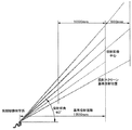
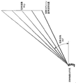
また、反射結像光学系を用いたフロントプロジェクションではなく、従来の屈折レンズ系を用いたフロントプロジェクションに於いて特有の問題点として指摘されるのは、フォーカス調整時の投射像の動きである。屈折光学系の場合一般に前玉のみを回転させるなどして繰り出し、スクリーンに投射された投射画像に対してフォーカスを調整する構成である。しかしながら、一般に屈折投射レンズの場合、代表的なものとしては図9に示すように画面内の下端に光軸が位置するようなかたちで上下方向の半画角分を使用するのが一般的である。そのため、フォーカス調整のために前玉を繰り出すなど調整を実行すると、投射画像上に於いて不動の点である投射屈折光学系の光軸は画面に対してオフセットしているため、多くの場合フォーカス調整に応じて画像は光軸の位置する投射画面下端付近を不動の中心として上方向に伸び縮みする。そのためフォーカス調整に応じて画像の位置がずれてしまい使い勝手が良くないと云う問題が生ずる。 In addition to the front projection using the reflective imaging optical system, the problem that is pointed out as a particular problem in the front projection using the conventional refractive lens system is the movement of the projected image during focus adjustment. In the case of a refracting optical system, in general, only the front lens is rotated, for example, and the focus is adjusted with respect to the projected image projected on the screen. However, in general, in the case of a refractive projection lens, as a typical example, as shown in FIG. 9, it is common to use a half angle of view in the vertical direction so that the optical axis is located at the lower end in the screen. is there. For this reason, when adjustments such as extending the front lens for focus adjustment are performed, the optical axis of the projection refractive optical system, which is a fixed point on the projected image, is offset with respect to the screen. In accordance with the adjustment, the image expands and contracts upward with the vicinity of the lower end of the projection screen where the optical axis is located as the center of immobility. Therefore, there arises a problem that the position of the image is shifted in accordance with the focus adjustment and the usability is not good.
この点に関して、図8に示す再公表特許特許の国際公開番号WO97/01787号公報に開示されている反射型ディスプレー装置における投射光学系の場合で考えると以下のような問題がある。本従来例にて反射面の一部を動かしてフォーカス調整を実現できると仮定したとして、例えば3d、3eに示される反射ミラーだけを動かそうとする場合、3a、3b、3d、3eに示される各面が全て共通の回転対称な軸を有するという配置の自由度に制限があるため、例えばその条件を維持した状態でこれら反射面を部分的に動かさなければならない。本従来例に於いて絞り3cの中心を通過する光線を本提案件では便宜上主光線と定義すると、このとき反射面3dと3eとの間の主光線の角度と、3eから投射スクリーンまでの主光線の角度は互いに平行ではなく、また該フォーカス調整によって3d、3eは、該各反射面の回転対称軸に沿って平行移動する必要があるため、投射画像に至る主光線の光軸は自動的に平行移動せざるを得ず、フォーカス調整によって投射画像の伸び縮みのみならず平行移動が生ずるという問題がある。
In this regard, the following problem arises in the case of the projection optical system in the reflective display device disclosed in International Publication No. WO97 / 01787 of the republished patent shown in FIG. Assuming that focus adjustment can be realized by moving a part of the reflecting surface in this conventional example, for example, when only the reflecting mirror shown in 3d and 3e is to be moved, it is shown in 3a, 3b, 3d and 3e. Since there is a limit to the degree of freedom in arrangement that all the surfaces have a common rotationally symmetric axis, for example, the reflecting surfaces must be partially moved while maintaining the conditions. In this conventional example, a light ray passing through the center of the
上記述べてきたように従来例の構成の場合、反射面は相互に共通な回転対称軸を有する位置関係を保っているので例えばどれかひとつだけの反射面を動かしてフォーカス調整しようとすると結像系としての収差バランスが崩れ結像系としての性能を発揮できない。これは所定の面だけを動かして焦点距離を調整するという前提で設計されていないことも原因と考えられる。そこで本提案件では軸外し反射型の結像光学系に於いて所定の複数の面で構成されている群を所定の方向に動かすことにより該結像光学系の焦点距離を調整することが出来るように予め反射面を配置し設計する。このときにフォーカス調整調整のために動かす群は投射角度に沿って移動させる構成にするため、フォーカス調整の結果画面サイズの変化や画面の移動、伸び縮みが例えば画面の中心を不動の点として拡大、縮小するように構成することが出来る。 As described above, in the case of the configuration of the conventional example, the reflecting surfaces maintain a positional relationship having a mutually common rotational symmetry axis, so that, for example, if one of the reflecting surfaces is moved to adjust the focus, the image is formed. The aberration balance as a system is lost, and the performance as an imaging system cannot be exhibited. This is also considered to be due to the fact that it is not designed on the assumption that the focal length is adjusted by moving only a predetermined surface. Therefore, in this proposal, the focal length of the imaging optical system can be adjusted by moving a group composed of a plurality of predetermined surfaces in a predetermined direction in the off-axis reflection type imaging optical system. The reflective surface is arranged and designed in advance. At this time, the group to be moved for focus adjustment adjustment is configured to move along the projection angle. As a result of focus adjustment, changes in the screen size, screen movement, and expansion / contraction expand, for example, using the center of the screen as a stationary point. , Can be configured to shrink.
まとめると下記のような条件に基づいて設計することになる。 In summary, the design is based on the following conditions.
(1)画像表示装置を経た光束を投射スクリーンに投射するための、曲面反射ミラーを複数枚組み合わせて構成した投射結像光学系であって、該投射画像に対するフォーカス調整機構を有する投射結像光学系である。 (1) A projection imaging optical system configured by combining a plurality of curved reflecting mirrors for projecting a light beam having passed through an image display device onto a projection screen, and having a focus adjustment mechanism for the projection image It is a system.
(2)フォーカス調整操作をしても投射画像の中心部分の位置が動かないことを特徴とする投射結像光学系である。 (2) The projection imaging optical system is characterized in that the position of the central portion of the projected image does not move even when a focus adjustment operation is performed.
(3)フォーカス調整は該光学系のうち、少なくとも2つの反射面をひとつのフォーカス調整のための群として定義し、該フォーカス調整群を所定の方向に所定の距離だけ移動することにより実現する。 (3) Focus adjustment is realized by defining at least two reflecting surfaces of the optical system as one focus adjustment group and moving the focus adjustment group by a predetermined distance in a predetermined direction.
(4)該フォーカス調整群は、該投射光学系の最も投射スクリーン側の面を含む。 (4) The focus adjustment group includes a surface closest to the projection screen of the projection optical system.
(5)該投射結像光学系に於いて、該画像表示装置から射出し、該投射結像光学系の絞り中心を通過し、該投射結像光学系を辿って該投射スクリーンへ至る一本の光線を基準軸光線と定義し、該画像表示装置から射出した直後の該基準軸光線の光路と、該投射スクリーンへ至る直前の該基準軸光線の光路は、互いに所定の角度を成す。(該角度が0°の場合があっても構わない)
(6)該フォーカス調整群は該スクリーンへ至る直前の基準軸光線の光路に対して略平行に移動する。
(5) In the projection imaging optical system, one that exits from the image display device, passes through the aperture center of the projection imaging optical system, and follows the projection imaging optical system to reach the projection screen. Are defined as reference axis rays, and the optical path of the reference axis rays immediately after exiting from the image display device and the optical path of the reference axis rays immediately before reaching the projection screen form a predetermined angle. (The angle may be 0 °)
(6) The focus adjustment group moves substantially parallel to the optical path of the reference axis light beam immediately before reaching the screen.
(7)該フォーカス調整群に入射する基準軸光線と、該フォーカス調整群から射出する基準軸光線、各々の方向余弦は互いに平行、且つ同符号である。 (7) The reference axis ray incident on the focus adjustment group and the reference axis ray emitted from the focus adjustment group, and the direction cosines thereof are parallel to each other and have the same sign.
(8)又は、該フォーカス調整群に入射する基準軸光線と、該フォーカス調整群から射出する基準軸光線、各々の方向余弦は互いに平行、且つ逆符号である。((7)との違いはフォーカス群の面数、構成に依存する)
(9)ここで光線の方向余弦とは該光線の進行方向に沿うベクトルであり、互いに略平行な範囲とは成す角度が1°以下である場合を示す。
(8) Or, the reference axis ray incident on the focus adjustment group and the reference axis ray emitted from the focus adjustment group, and the direction cosines thereof are parallel to each other and have opposite signs. (The difference from (7) depends on the number of faces and configuration of the focus group)
(9) Here, the direction cosine of the light beam is a vector along the traveling direction of the light beam, and indicates a case where the angle formed with the substantially parallel range is 1 ° or less.
(10)該フォーカス調整群を構成する面が2面である場合、該2面のパワーは共に正である。 (10) When there are two surfaces constituting the focus adjustment group, the powers of the two surfaces are both positive.
(11)該フォーカス調整群を構成する少なくとも3つの反射面は、隣接する面同士で相互にパワーが逆であり、且つ最終面のパワーが正である。 (11) At least three reflecting surfaces constituting the focus adjustment group have mutually opposite powers, and the final surface has a positive power.
(12)上記曲面反射ミラーの少なくともひとつは非回転対称な自由形状を呈する自由曲面ミラーである。 (12) At least one of the curved reflecting mirrors is a free curved mirror having a non-rotationally symmetric free shape.
(13)上記曲面反射ミラーの少なくともひとつは表面に回折格子形状を有するミラーである。 (13) At least one of the curved reflecting mirrors is a mirror having a diffraction grating shape on the surface.
(14)上記曲面反射ミラーの少なくともひとつは表面反射ミラーである。 (14) At least one of the curved reflecting mirrors is a surface reflecting mirror.
(15)上記曲面反射ミラーの少なくともひとつは裏面反射ミラーである。 (15) At least one of the curved reflecting mirrors is a back reflecting mirror.
(16)上記表面曲面反射ミラーの少なくともひとつは樹脂又はガラスで成形したものの表面に高反射のコーティングを施したものである。 (16) At least one of the above-mentioned curved surface reflecting mirrors is made of a resin or glass and has a surface with a highly reflective coating.
(17)上記表面曲面反射ミラーの少なくともひとつは金属の薄板をプレス成形して所定の形状を転写したものの表面に高反射のコーティングを施したものである。 (17) At least one of the above-mentioned curved curved surface reflecting mirrors is obtained by applying a highly reflective coating to the surface of a metal sheet that has been press-molded to transfer a predetermined shape.
(18)上記裏面曲面反射ミラーの少なくともひとつは樹脂又はガラスで成形したものの裏面に高反射のコーティングを施したものである。 (18) At least one of the back surface curved reflecting mirrors is made of resin or glass, and has a highly reflective coating on the back surface.
本発明により、投射装置の自由曲面ミラーを複数組み合わせて構成した画像投射結像光学系で、フォーカス調整群を部分的に移動することでフォーカス調整を実効可能な系を実現出来る。 According to the present invention, it is possible to realize a system capable of performing focus adjustment by partially moving the focus adjustment group in an image projection imaging optical system configured by combining a plurality of free-form surface mirrors of the projection apparatus.
本実施形態の説明に入る前に、実施形態の構成諸元の表し方及び実施形態全体の共通事項について説明する。 Prior to the description of the present embodiment, description will be given of how to represent the configuration specifications of the embodiment and common matters of the entire embodiment.
本発明の実施形態では物体側から像面に進む光線の到達する順序に従って第m番目の面を第m面とする。各反射面はガラス、プラスチック等で成形された表面形状に反射膜などを付着させた表面反射ミラーであり、各ミラー間の空間を満たす媒質は空気である。従って、本実施例は全て所謂中空型である。一方で、ガラスやプラスチックのバルクの表面に該自由曲面を複数形成して反射膜を付け、裏面ミラーとして、該媒質内部を光束が伝搬する構成でも構わない。 In the embodiment of the present invention, the m-th surface is defined as the m-th surface in the order of arrival of rays traveling from the object side to the image plane. Each reflecting surface is a surface reflecting mirror in which a reflecting film or the like is attached to a surface shape formed of glass, plastic or the like, and the medium filling the space between the mirrors is air. Therefore, all the examples are so-called hollow types. On the other hand, a configuration in which a plurality of free curved surfaces are formed on the surface of a glass or plastic bulk, a reflective film is attached, and a light beam propagates through the medium as a back mirror.
実施形態を説明するために、まず基準軸光線、グローバル座標系、ローカル座標系の三つの項目について定義し説明する。 In order to describe the embodiment, first, three items of a reference axis ray, a global coordinate system, and a local coordinate system are defined and described.
本発明の光学系はOff-Axial光学系であるため光学系を構成する各面は共通の光軸を持っていない。繰返しになるが、本発明の実施形態においては、先ず物体である画像表示装置から射出され該結像光学系を辿りながら像面へ至る一本の光線であって、光学系の絞り中心を通過する光線を基準と考え、該光線を基準軸光線と定義する。該基準軸光線は方向(向き)を持っている。その方向は基準の光線が結像に際して進行する方向である。基準軸光線は設定された各面の順番に沿って反射の法則に従ってその方向を変化させつつ、絞りの中心を通り、最終的に像面の中心に到達する。 Since the optical system of the present invention is an off-axial optical system, the surfaces constituting the optical system do not have a common optical axis. To repeat, in the embodiment of the present invention, first, a light beam that is emitted from the image display device that is an object and reaches the image plane while following the imaging optical system, and passes through the center of the stop of the optical system. The light beam to be used is regarded as a reference, and the light beam is defined as a reference axis light beam. The reference axis ray has a direction (orientation). The direction is the direction in which the reference ray travels during imaging. The reference axis ray passes through the center of the stop and finally reaches the center of the image plane while changing its direction in accordance with the law of reflection along the set order of each surface.
次に、画像表示装置である物体面の中心の点を原点とするグローバル座標系(グローバル座標は大文字XYZで表現する)を考え、グローバル座標系の各軸を以下のように定め、図1を用いて説明する。尚、座標系は右手系とする。 Next, consider a global coordinate system (the global coordinates are expressed in capital letters XYZ) with the origin at the center point of the object plane that is the image display device, and determine each axis of the global coordinate system as follows, and FIG. It explains using. The coordinate system is a right-handed system.
(1)Z軸:図1に示すようにグローバル原点を通り、物体面から第1ミラーに向かう方向を正とする。 (1) Z axis: As shown in FIG. 1, the direction from the object plane toward the first mirror through the global origin is positive.
(2)Y軸:図1に示すようにグローバル原点を通りZ軸に対して90゜をなす直線。図1に於いて図上方をY軸の正符号方向とする。本発明において、上記基準軸光線はYZ面内に存在するものとする。従って、本発明の各実施形態の反射結像光学系を構成する曲面ミラーはすべてがYZ面内でチルトしている。本発明の各実施形態の各図に於いて紙面はYZ面内と一致する。また、上記座標系は本発明の各実施形態の各図に於いて共通であり、Y軸の正方向は図面上側である。 (2) Y axis: A straight line that passes through the global origin and forms 90 ° with respect to the Z axis as shown in FIG. In FIG. 1, the upper side of the drawing is the positive sign direction of the Y axis. In the present invention, it is assumed that the reference axis ray exists in the YZ plane. Therefore, all the curved mirrors constituting the reflective imaging optical system of each embodiment of the present invention are tilted in the YZ plane. In each figure of each embodiment of the present invention, the paper plane coincides with the YZ plane. The coordinate system is common in the drawings of the embodiments of the present invention, and the positive direction of the Y-axis is the upper side of the drawing.
(3)X軸:原点を通りZ,Y各軸に垂直な直線。即ち、各図の紙面に垂直な方向の直線である。右手系なので正は紙面奥側となる。 (3) X axis: A straight line that passes through the origin and is perpendicular to the Z and Y axes. That is, it is a straight line in a direction perpendicular to the paper surface of each figure. Since it is a right-handed system, the positive is the back side of the page.
光学系を構成する第m面の面形状を表現するには、グローバル座標系にてその面の形状を表記するより、基準軸光線上を面間隔だけ進んだ点をローカル原点とするローカル座標系(ローカル座標は小文字xyzで表現する)を設定して、各面毎に対応したローカル座標系でその面の面形状を表した方が形状を認識する上で理解し易いため、第m面の面形状をローカル座標系(右手系)で表わす。また、面のチルトも各面に対応するローカル座標系をチルトさせることにより表現することとする。第m面に対応するローカル座標系のYZ面内でのチルト角はグローバル座標系のZ軸に対して反時計回り方向を正とした角度θm(単位[°])で表す。よって、当然のことながら本発明の実施形態では各面のローカル座標の原点は全てYZ平面上にある。またXZおよびXY面内での面の偏心はない。さらに、第m面のローカル座標(x,y,z)のy,z軸はグローバル座標系(X,Y,Z)に対してYZ面内で角度θm傾いており、具体的には以下のように設定する。 In order to express the surface shape of the m-th surface constituting the optical system, the local coordinate system has a local origin as a point advanced on the reference axis ray by a surface interval rather than describing the shape of the surface in the global coordinate system. (The local coordinates are expressed in lower case xyz), and it is easier to understand the shape of the m-th surface because it is easier to understand the shape by expressing the surface shape of the surface in the local coordinate system corresponding to each surface. The surface shape is expressed in the local coordinate system (right hand system). The tilt of the surface is also expressed by tilting the local coordinate system corresponding to each surface. The tilt angle in the YZ plane of the local coordinate system corresponding to the m-th plane is represented by an angle θm (unit [°]) with the counterclockwise direction being positive with respect to the Z axis of the global coordinate system. Therefore, as a matter of course, in the embodiment of the present invention, the origins of the local coordinates of each surface are all on the YZ plane. There is no surface eccentricity in the XZ and XY planes. Furthermore, the y and z axes of the local coordinates (x, y, z) of the mth plane are inclined at an angle θm in the YZ plane with respect to the global coordinate system (X, Y, Z). Set as follows.
(1)z軸:ローカル座標の原点を通り、グローバル座標系のZ方向に対しYZ面内において反時計方向に角度θmをなす直線。 (1) z-axis: a straight line that passes through the origin of local coordinates and forms an angle θm counterclockwise in the YZ plane with respect to the Z direction of the global coordinate system.
(2)y軸:ローカル座標の原点を通り、z方向に対しYZ面内において反時計方向に90゜をなす直線。 (2) y-axis: A straight line that passes through the origin of local coordinates and forms 90 ° counterclockwise in the YZ plane with respect to the z direction.
(3)x軸:ローカル座標の原点を通り、YZ面に対し垂直な直線。 (3) x-axis: A straight line passing through the origin of local coordinates and perpendicular to the YZ plane.
(4)Lmは第m面と第m+1面のローカル座標の原点間の間隔を表すスカラー量である。(単位[mm])
但し、最終面に関しては面のローカル原点から像面の中心までの距離を示す。
(4) Lm is a scalar quantity that represents the distance between the origins of the local coordinates of the mth and m + 1th planes. (Unit [mm])
However, for the final surface, the distance from the local origin of the surface to the center of the image surface is shown.
本発明の光学系は少なくとも回転非対称な非球面を一面以上有し、その形状はローカル座標系上に以下の(1)式により表す:
但し、C02、C20、C03、C21、C04、C22、C40、C05、C23、C41、C06、C24、C42、C60は、非球面係数である。
The optical system of the present invention has at least one rotationally asymmetric aspheric surface, and the shape thereof is represented by the following equation (1) on the local coordinate system:
However, C02, C20, C03, C21, C04, C22, C40, C05, C23, C41, C06, C24, C42, and C60 are aspheric coefficients.
z(x、y)=C02y2+C20x2+C03y3+C21x2y+C04y4+C22x2y2
+C40x4+C05y5+C23x2y3+C41x4y+C06y6+C24x2y4
+C42x4y2+C60x6‥‥(1)
上記曲面(1)式は平面をベースとする回転非対称面を表し、xに関して偶数次の項のみであるため、上記曲面式により規定される曲面はyz面を対称面とする面対称な形状である。さらに以下の条件が満たされる場合はxz面に対して対称な形状を表す。
z (x, y) = C02y 2 + C20x 2 +
+ C40x 4 + C05y 5 + C23x 2 y 3 + C41x 4 y + C06y 6 + C24x 2 y 4
+ C42x 4 y 2 + C60x 6 (1)
Since the curved surface (1) represents a rotationally asymmetric surface based on a plane and is only an even-order term with respect to x, the curved surface defined by the curved surface equation has a plane-symmetric shape with the yz plane as a symmetric surface. is there. Furthermore, when the following conditions are satisfied, the shape is symmetric with respect to the xz plane.
C03=C21=C05=C23=C41=0
さらに
C02=C20、C04=C40=C22/2、C06=C60=C24/3=C42/3
が満たされる場合は回転対称な形状を表す。以上の条件を満たさない場合は非回転対称な形状である。
C03 = C21 = C05 = C23 = C41 = 0
further
C02 = C20, C04 = C40 = C22 / 2, C06 = C60 = C24 / 3 = C42 / 3
Represents a rotationally symmetric shape. When the above conditions are not satisfied, the shape is non-rotationally symmetric.
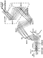
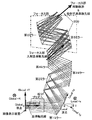
次に本発明の各実施形態について説明する。図1〜2に示すのは、自由曲面反射結像光学系のミラー部分の図及び投射スクリーン(投射像)までの光路全体の図である。 Next, each embodiment of the present invention will be described. FIGS. 1 and 2 are a diagram of a mirror portion of a free-form surface reflection imaging optical system and a diagram of the entire optical path to a projection screen (projection image).
図1は本発明の投射光学系を用いた投射型表示装置の第1実施形態の要部概略図である。 FIG. 1 is a schematic view of a main part of a first embodiment of a projection display device using the projection optical system of the present invention.
本実施例は画像表示装置により光強度変調された光を投射スクリーンに投射し、投射スクリーン面上に画像を形成するためのOff-Axial系を利用した投射光学系である。図2は図1の投射光学系の全体図である。 This embodiment is a projection optical system using an off-axial system for projecting light whose intensity has been modulated by an image display device onto a projection screen and forming an image on the projection screen surface. FIG. 2 is an overall view of the projection optical system of FIG.
図1において物体面は画像表示装置の面と一致している。該画像表示装置は不図示の照明系により裏側から照明される。不図示の照明系はランプ、コンデンサーレンズ、波長を選択するフィルターなどから成り立っている。また本実施形態ではRGBの3枚の画像表示装置を使用し色合成プリズムを用いてRGB3色の画像を合成して投射する構成であるが、2枚の画像表示装置は不図示である。ひとつの画像表示装置と色合成プリズムが図示されている。これは全ての実施例について共通であるが、
(1)反射曲面総数は6面
(2)物体面から色合成プリズムまでの距離:11.0
(3)色合成プリズム厚さ:28.0
(4)Nd:1.872690、νd:32.33
(5)プリズム射出端面から第1ミラーのローカル座標原点までの距離:40.0
(単位[mm])である。
In FIG. 1, the object plane coincides with the plane of the image display device. The image display device is illuminated from the back side by an illumination system (not shown). The illumination system (not shown) includes a lamp, a condenser lens, a filter for selecting a wavelength, and the like. In the present embodiment, three RGB image display devices are used to synthesize and project RGB three color images using a color synthesis prism, but the two image display devices are not shown. An image display device and a color synthesis prism are shown. This is common for all examples,
(1) The total number of reflection curved surfaces is six. (2) Distance from object surface to color synthesis prism: 11.0
(3) Color composition prism thickness: 28.0
(4) Nd: 1.872690, νd: 32.33
(5) Distance from prism exit end surface to local coordinate origin of first mirror: 40.0
(Unit [mm]).
図1、図2において、反射結像光学系は画像表示装置からの光線の通過順に、第1ミラー(凹面)・絞り・第2ミラー(凸面)・第3ミラー(凹面)・第4ミラー(凸面)・第5ミラー(凹面)・第6面ラー(凹面)の6つの反射面で構成されている。すべての反射面はYZ平面のみに対して対称な面である。ここで、第4ミラーと第5ミラーの間で画像表示装置による画像は中間結像しており、絞りは第6ミラー後の位置で結像している。 1 and 2, the reflective imaging optical system includes a first mirror (concave surface), a diaphragm, a second mirror (convex surface), a third mirror (concave surface), a fourth mirror (in order of passage of light rays from the image display device). Convex surface), 5th mirror (concave surface), and 6th surface mirror (concave surface). All reflecting surfaces are symmetrical with respect to the YZ plane only. Here, an image formed by the image display device forms an intermediate image between the fourth mirror and the fifth mirror, and the diaphragm is formed at a position after the sixth mirror.
本提案に於ける全ての実施形態では、画像表示装置は対角0.7インチ(10.7×14.2mm)、投射スクリーンの大きさは縦横比3:4の対角70インチ(1067×1422mm)である。また、投射スクリーンの法線は、投射スクリーンに入射する直前の基準軸光線に対し40度傾いている。画像表示装置は所謂XGA(1024×768画素)であり、画素のピッチはスクリーン側で1.4mmであり、このときの空間遮断周波数は1/2.8=0.36本/mmである。 In all the embodiments in this proposal, the image display device has a diagonal size of 0.7 inch (10.7 × 14.2 mm), and the projection screen has a size of 70 inches (1067 × 1067 × 3) with an aspect ratio of 3: 4. 1422 mm). Further, the normal line of the projection screen is inclined by 40 degrees with respect to the reference axis light beam immediately before entering the projection screen. The image display apparatus is a so-called XGA (1024 × 768 pixels), and the pixel pitch is 1.4 mm on the screen side, and the spatial cutoff frequency at this time is 1 / 2.8 = 0.36 lines / mm.
実際の装置の使用状態を考慮した設置形態のひとつの例である、投射スクリーンの面が鉛直方向に平行であるように、且つ基準軸光線全てを含む平面を該投射スクリーンに垂直な鉛直面内になるように装置を設置した場合、装置の最終反射面からスクリーンまで水平方向に測った場合の投射距離は、L6×Cos40°=1963mm×Cos40°=1500mmである。この投射距離が設計時の基準となっている。
An example of an installation configuration that takes into account the actual use state of the apparatus, such that the plane of the projection screen is parallel to the vertical direction, and a plane including all the reference axis rays is within the vertical plane perpendicular to the projection screen. When the device is installed so that the projection distance is measured in the horizontal direction from the final reflection surface of the device to the screen, the projection distance is L6 ×
下記に第1実施例の設計値を示す。構成データではパネル面から像面(投射スクリーン面)に至る各面に順に番号を付している。 The design values of the first embodiment are shown below. In the configuration data, each surface from the panel surface to the image surface (projection screen surface) is numbered sequentially.
物体側のF値は2.8。 The F value on the object side is 2.8.
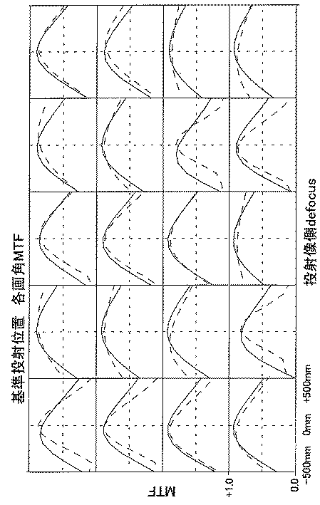
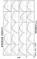
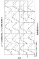
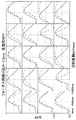
第1実施例に於いて、第5面と第6面の2つので構成される群がフォーカス群である。ここで、第5面のチルト角θ5と第6面のチルト角θ6はそれぞれ5°と5°であり等しい。グローバル座標系のZ軸に対して、フォーカス群に入射する基準軸光線が成す角度は、40°であり、フォーカス群を射出する基準軸光線がグローバルZ軸に対して成す角度は、同じく40°である。該フォーカス群はこの光軸に平行な、グローバルZ軸に対して40°の角度を成す方向軸に平行移動することでフォーカス調整機能を有する。第3図は第1実施例の基準となる前述の投射距離1500mmに於ける像面上各点のMTFのdefocus特性である。同図に於いて横軸はdefocus量であり、0の点が基準の像面の位置(基準投射位置)である。defocus量は、前述の基準投射距離を測った水平方向に沿って測ったものである。この時の空間周波数は画像表示装置の画素ピッチから決まる投射スクリーン側に於ける周波数0.36本/mmである。第4図は、該フォーカス調整群を+0.7mm繰り出した時、上記基準投射距離から−1000mm手前側に移動した像面に於けるMTFである。また、第5図は、該フォーカス調整群を−0.3mm繰り込んだ時、上記基準投射距離から+500mm遠ざかる側に移動した像面に於けるMTFである。このように±500mm以上の範囲で画面全体に十分にフォーカスの合わせられた画像を投射することが出来る。尚、上記繰り出し、繰り込みの値、及び像面の変位の符号は、光線進行方向を正としているため、繰り込み量及び手前側への移動量は負の値として表現している。 In the first embodiment, the group composed of the fifth surface and the sixth surface is the focus group. Here, the tilt angle θ5 of the fifth surface and the tilt angle θ6 of the sixth surface are 5 ° and 5 °, respectively, and are equal. The angle formed by the reference axis ray incident on the focus group with respect to the Z axis of the global coordinate system is 40 °, and the angle formed by the reference axis ray emitted from the focus group with respect to the global Z axis is also 40 °. It is. The focus group has a focus adjustment function by moving parallel to a direction axis that is parallel to the optical axis and forms an angle of 40 ° with the global Z axis. FIG. 3 shows the defocus characteristics of the MTF at each point on the image plane at the above-mentioned projection distance of 1500 mm, which is the reference for the first embodiment. In the figure, the horizontal axis is the defocus amount, and the zero point is the position of the reference image plane (reference projection position). The defocus amount is measured along the horizontal direction in which the reference projection distance is measured. The spatial frequency at this time is 0.36 lines / mm on the projection screen side determined from the pixel pitch of the image display device. FIG. 4 shows the MTF on the image plane moved to the front side of −1000 mm from the reference projection distance when the focus adjustment group is extended by +0.7 mm. FIG. 5 shows the MTF on the image plane moved to the side away from the reference projection distance by +500 mm when the focus adjustment group is retracted by −0.3 mm. Thus, an image that is sufficiently focused on the entire screen can be projected in a range of ± 500 mm or more. In addition, since the sign of the drawing-out, the drawing-in value, and the displacement of the image plane has a positive ray traveling direction, the drawing-in amount and the amount of movement toward the front side are expressed as negative values.
図6は本発明の投射光学系を用いた投射型表示装置の第2実施形態の要部概略図である。 FIG. 6 is a schematic view of the essential portions of a second embodiment of a projection display apparatus using the projection optical system of the present invention.
本実施例は画像表示装置により光強度変調された光を投射スクリーンに投射し、投射スクリーン面上に画像を形成するためのOff-Axial系を利用した投射光学系である。図7は図6の投射光学系の外観図である。 This embodiment is a projection optical system using an off-axial system for projecting light whose intensity has been modulated by an image display device onto a projection screen and forming an image on the projection screen surface. FIG. 7 is an external view of the projection optical system of FIG.
図6において物体面は画像表示装置の面と一致している。該画像表示装置は不図示の照明系により裏側から照明される。不図示の照明系はランプ、コンデンサーレンズ、波長を選択するフィルターなどから成り立っている。また本実施形態ではRGBの3枚の画像表示装置を使用し色合成プリズムを用いてRGB3色の画像を合成して投射する構成であるが、2枚の画像表示装置は不図示である。ひとつの画像表示装置と色合成プリズムが図示されている。これは全ての実施例について共通である。 In FIG. 6, the object plane coincides with the plane of the image display device. The image display device is illuminated from the back side by an illumination system (not shown). The illumination system (not shown) includes a lamp, a condenser lens, a filter for selecting a wavelength, and the like. In the present embodiment, three RGB image display devices are used to synthesize and project RGB three color images using a color synthesis prism, but the two image display devices are not shown. An image display device and a color synthesis prism are shown. This is common to all embodiments.
図6、図7において、反射結像光学系は画像表示装置からの光線の通過順に、第1ミラー(凹面)・絞り・第2ミラー(凸面)・第3ミラー(凹面)・第4ミラー(凸面)・第5ミラー(凹面)・第6面ラー(凹面)の6つの反射面で構成されている。すべての反射面はYZ平面のみに対して対称な面である。ここで、第5ミラーと第6ミラーの間で画像表示装置による画像は中間結像しており、絞りは第6ミラー後の位置で結像している。 6 and 7, the reflective imaging optical system includes a first mirror (concave surface), an aperture, a second mirror (convex surface), a third mirror (concave surface), a fourth mirror (in order of passage of light rays from the image display device). Convex surface), 5th mirror (concave surface), and 6th surface mirror (concave surface). All reflecting surfaces are symmetrical with respect to the YZ plane only. Here, an image formed by the image display device is intermediately formed between the fifth mirror and the sixth mirror, and the diaphragm is formed at a position after the sixth mirror.
本提案に於ける全ての実施形態では、画像表示装置は対角0.7インチ(10.7×14.2mm)、投射スクリーンの大きさは縦横比3:4の対角70インチ(1067×1422mm)である。また、投射スクリーンの法線は、投射スクリーンに入射する直前の基準軸光線に対し40度傾いている。画像表示装置は所謂XGA(1024×768画素)であり、画素のピッチはスクリーン側で1.4mmであり、このときの空間遮断周波数は1/2.8=0.36本/mmである。 In all the embodiments in this proposal, the image display device has a diagonal size of 0.7 inch (10.7 × 14.2 mm), and the projection screen has a size of 70 inches (1067 × 1067 × 3) with an aspect ratio of 3: 4. 1422 mm). Further, the normal line of the projection screen is inclined by 40 degrees with respect to the reference axis light beam immediately before entering the projection screen. The image display apparatus is a so-called XGA (1024 × 768 pixels), and the pixel pitch is 1.4 mm on the screen side, and the spatial cutoff frequency at this time is 1 / 2.8 = 0.36 lines / mm.
実際の装置の使用状態を考慮した設置形態のひとつの例である、投射スクリーンの面が鉛直方向に平行であるように、且つ基準軸光線全てを含む平面を該投射スクリーンに垂直な鉛直面内になるように装置を設置した場合、装置の最終反射面からスクリーンまで水平方向に測った場合の投射距離は、L6×Cos40°=2200mm×Cos40°=1685mmである。この投射距離が設計時の基準となっている。
An example of an installation configuration that takes into account the actual use state of the apparatus, such that the plane of the projection screen is parallel to the vertical direction, and a plane including all the reference axis rays is within the vertical plane perpendicular to the projection screen. When the apparatus is installed so that the projection distance is measured in the horizontal direction from the final reflecting surface of the apparatus to the screen, the projection distance is L6 ×
下記に第1実施例の設計値を示す。構成データではパネル面から像面(投射スクリーン面)に至る各面に順に番号を付している。 The design values of the first embodiment are shown below. In the configuration data, each surface from the panel surface to the image surface (projection screen surface) is numbered sequentially.
下記に第2実施例の設計値を示す。(単位は[mm]と[°])
物体側のF値は2.0。
The design values of the second embodiment are shown below. (Units are [mm] and [°])
The F value on the object side is 2.0.
第二実施例に於いて、第5面と第6面の2つので構成される群がフォーカス群である。ここで、第5面のチルト角θ5と第6面のチルト角θ6はそれぞれ14°と14°であり等しい。グローバル座標系のZ軸に対して、フォーカス群に入射する基準軸光線の成す角度は、40°であり、フォーカス群を射出する基準軸光線の同様にグローバルZ軸に対して成す角度は同じく40°である。該フォーカス群はこの光軸に平行な、グローバルZ軸に対して40°の角度を成す方向軸に平行移動することでフォーカス調整機能を有する。 In the second embodiment, the group composed of the fifth surface and the sixth surface is the focus group. Here, the tilt angle θ5 of the fifth surface and the tilt angle θ6 of the sixth surface are 14 ° and 14 °, respectively, and are equal. The angle formed by the reference axis ray incident on the focus group with respect to the Z axis of the global coordinate system is 40 °, and the angle formed by the global Z axis similarly for the reference axis ray emitted from the focus group is also 40. °. The focus group has a focus adjustment function by moving in parallel with a direction axis that is parallel to the optical axis and forms an angle of 40 ° with the global Z axis.
図は省略するが本実施例についても第1実施例と同様に適宜フォーカス群を繰り出し、又は繰り込みを行うことにより、基準投射位置の前後の所定の実用的な範囲で、十分なMTFのレスポンスを有している。 Although not shown, in this embodiment as well, in the same manner as in the first embodiment, a sufficient MTF response is obtained within a predetermined practical range before and after the reference projection position by appropriately extending or retracting the focus group. Have.
Claims (17)
14. The projection imaging optical system according to claim 13, wherein at least one of the back curved reflectors is made of resin or glass and has a highly reflective coating on the back.
Priority Applications (1)
| Application Number | Priority Date | Filing Date | Title |
|---|---|---|---|
| JP2003336903A JP2005106900A (en) | 2003-09-29 | 2003-09-29 | Projection imaging optical system |
Applications Claiming Priority (1)
| Application Number | Priority Date | Filing Date | Title |
|---|---|---|---|
| JP2003336903A JP2005106900A (en) | 2003-09-29 | 2003-09-29 | Projection imaging optical system |
Publications (1)
| Publication Number | Publication Date |
|---|---|
| JP2005106900A true JP2005106900A (en) | 2005-04-21 |
Family
ID=34532877
Family Applications (1)
| Application Number | Title | Priority Date | Filing Date |
|---|---|---|---|
| JP2003336903A Withdrawn JP2005106900A (en) | 2003-09-29 | 2003-09-29 | Projection imaging optical system |
Country Status (1)
| Country | Link |
|---|---|
| JP (1) | JP2005106900A (en) |
Cited By (4)
| Publication number | Priority date | Publication date | Assignee | Title |
|---|---|---|---|---|
| JP2007233056A (en) * | 2006-03-01 | 2007-09-13 | Necディスプレイソリューションズ株式会社 | Projection display apparatus |
| JP2008158495A (en) * | 2006-11-28 | 2008-07-10 | Seiko Epson Corp | projector |
| US8113667B2 (en) | 2007-03-01 | 2012-02-14 | Konica Minolta Opto, Inc. | Projection optical system |
| US8425044B2 (en) | 2007-03-01 | 2013-04-23 | Konica Minolta Opto, Inc. | Projection optical system |
-
2003
- 2003-09-29 JP JP2003336903A patent/JP2005106900A/en not_active Withdrawn
Cited By (4)
| Publication number | Priority date | Publication date | Assignee | Title |
|---|---|---|---|---|
| JP2007233056A (en) * | 2006-03-01 | 2007-09-13 | Necディスプレイソリューションズ株式会社 | Projection display apparatus |
| JP2008158495A (en) * | 2006-11-28 | 2008-07-10 | Seiko Epson Corp | projector |
| US8113667B2 (en) | 2007-03-01 | 2012-02-14 | Konica Minolta Opto, Inc. | Projection optical system |
| US8425044B2 (en) | 2007-03-01 | 2013-04-23 | Konica Minolta Opto, Inc. | Projection optical system |
Similar Documents
| Publication | Publication Date | Title |
|---|---|---|
| JP4015851B2 (en) | Imaging optics | |
| US6779897B2 (en) | Rear projection optical system | |
| JP5374848B2 (en) | Projection optical system | |
| JP5365155B2 (en) | Projection-type image display device and projection optical system | |
| JP7099460B2 (en) | Image display device and projection optical system | |
| JP2023155289A (en) | Optical system, image projection device and imaging device | |
| CN101794063B (en) | Projection type image display apparatus | |
| CN105892025B (en) | Projection optical system | |
| JPWO2001006295A1 (en) | Imaging optical system | |
| JP2007322811A (en) | Projection optical unit and projection display apparatus using the same | |
| CN113176699B (en) | Projection optical system and projector | |
| JP4086686B2 (en) | Projection optical system, projection-type image display device and image display system | |
| CN113176698B (en) | Projection optical system and projector | |
| US7503661B2 (en) | Projection optical system | |
| JP2008090200A (en) | Zoom lens and projection-type image display device | |
| JP2003043360A (en) | Imaging optical system, projection-type image display device, and imaging device | |
| JP2006184775A (en) | Reflection optical system and projection type display device using same | |
| JP2008242028A (en) | Projection optical system | |
| JP2004295107A (en) | Variable power optical system | |
| JP4016007B2 (en) | Imaging optics | |
| JP4478408B2 (en) | Imaging optical system, imaging device, image reading device, and projection-type image display device | |
| JP4016008B2 (en) | Imaging optics | |
| CN111948886A (en) | Projection imaging device | |
| CN113219771B (en) | Projection optics and projectors | |
| KR20180088249A (en) | Ultra short focus projector |
Legal Events
| Date | Code | Title | Description |
|---|---|---|---|
| A300 | Application deemed to be withdrawn because no request for examination was validly filed |
Free format text: JAPANESE INTERMEDIATE CODE: A300 Effective date: 20061205 |