JP2005123739A - COMMUNICATION SYSTEM, TERMINAL DEVICE, COMMUNICATION SYSTEM CONTROL METHOD, RECORDING MEDIUM, AND PROGRAM - Google Patents
COMMUNICATION SYSTEM, TERMINAL DEVICE, COMMUNICATION SYSTEM CONTROL METHOD, RECORDING MEDIUM, AND PROGRAM Download PDFInfo
- Publication number
- JP2005123739A JP2005123739A JP2003354142A JP2003354142A JP2005123739A JP 2005123739 A JP2005123739 A JP 2005123739A JP 2003354142 A JP2003354142 A JP 2003354142A JP 2003354142 A JP2003354142 A JP 2003354142A JP 2005123739 A JP2005123739 A JP 2005123739A
- Authority
- JP
- Japan
- Prior art keywords
- data
- control
- node
- transmission
- receiving
- Prior art date
- Legal status (The legal status is an assumption and is not a legal conclusion. Google has not performed a legal analysis and makes no representation as to the accuracy of the status listed.)
- Pending
Links
Images


Landscapes
- Small-Scale Networks (AREA)
Abstract
Description
本発明は、通信システム、端末装置、通信システムの制御方法、記録媒体およびプログラムに関し、特に、制御信号とデータとを混在させて通信可能なデータ通信バスを介して、複数の電子機器を通信可能なように接続し、各機器間でデータ通信を行う通信システムに用いて好適なものである。 The present invention relates to a communication system, a terminal device, a communication system control method, a recording medium, and a program, and in particular, can communicate with a plurality of electronic devices via a data communication bus capable of communicating by mixing control signals and data. Therefore, it is suitable for use in a communication system that performs data communication between devices.
パーソナル・コンピュータ(以下、「PC」と称す。)の周辺機器の中で、ハードディスクやプリンタは利用頻度が高く、小型コンピュータ用汎用型インターフェースで代表的なデジタルインターフェース(以下、「デジタルI/F」と称す。)であるSCSI(Small Computer System Interface)等を用いてPCに対して接続され、データ通信が行われている。また、デジタルカメラやデジタルビデオカメラ等の画像記録再生装置も、PCとの間でデータ通信可能な周辺機器の1つであり、近年、画像記録再生装置により撮影した映像(静止画像や動画像)をPCに取り込んで、ハードディスクに記憶保存したり、またはPCを用いて編集した後、プリンタでカラー印刷したりする技術が発達し、画像記録再生装置により撮影した映像を保存、編集するユーザーも増加している。 Among peripheral devices of personal computers (hereinafter referred to as “PCs”), hard disks and printers are frequently used, and digital interfaces (hereinafter referred to as “digital I / Fs”) that are typical general-purpose interfaces for small computers. Data communication is performed by connecting to a PC using a SCSI (Small Computer System Interface) or the like. An image recording / reproducing apparatus such as a digital camera or a digital video camera is also one of peripheral devices capable of data communication with a PC. In recent years, images (still images and moving images) taken by the image recording / reproducing apparatus are used. Has been developed to capture and store images on a hard disk, store them on a hard disk, or edit them using a PC, and then print them in color on a printer. doing.
上述のように、取り込んだ画像データをPCからプリンタやハードディスクに出力する際などには、上記SCSI等のデジタルI/Fを介してデータ通信が行われるので、画像データのようにデータ量が多い情報を送るためにも、転送データレートが高く、かつ汎用性を有するデジタルI/Fが必要とされる。このような要望に応えるものとして、IEEE1394規格に準拠したデータ通信バス(以下、「1394シリアルバス」と称す。)がある。 As described above, when the captured image data is output from the PC to a printer or hard disk, data communication is performed via the digital I / F such as the SCSI, so that the amount of data is as large as the image data. In order to send information, a digital I / F having a high transfer data rate and versatility is required. As a response to such a demand, there is a data communication bus (hereinafter referred to as “1394 serial bus”) compliant with the IEEE 1394 standard.
以下に、1394シリアルバスの概要について説明する。
家庭用デジタルVTRやDVDの登場に伴い、ビデオデータやオーディオデータ等のリアルタイム性が要求され、かつ情報量が多いデータを、リアルタイムで転送して、PCに取り込んだり、その他のデジタル機器に転送したりするには、高速データ転送可能なデジタルI/Fが必要である。そのような観点から開発されたデジタルI/F規格の1つが、IEEE1394−1995規格(High Performance Serial Bus)である。
The outline of the 1394 serial bus will be described below.
With the advent of home digital VTRs and DVDs, real-time data such as video data and audio data is required, and data with a large amount of information is transferred in real time and taken into a PC or transferred to other digital devices. To do this, a digital I / F capable of high-speed data transfer is required. One of the digital I / F standards developed from such a viewpoint is the IEEE 1394-1995 standard (High Performance Serial Bus).
1394シリアルバスにおける各機器間の接続方式は、デイジーチェーン方式とノード分岐方式とを混在可能としたものであり、高い自由度で各機器を接続することができる。また、各機器は、固有のノードIDをそれぞれ有し、互いに認識し合うことによって、1394シリアルバスを介して接続された範囲において1つのネットワークを構成する。各機器間をそれぞれ1本の1394シリアルバスケーブルで順次接続するだけで、それぞれの機器が中継の役割を担い、全体として1つのネットワークを構成するものである。 The connection method between the devices in the 1394 serial bus is such that the daisy chain method and the node branching method can be mixed, and each device can be connected with a high degree of freedom. Each device has a unique node ID and recognizes each other, thereby forming one network in a range connected via the 1394 serial bus. By simply connecting each device sequentially with a single 1394 serial bus cable, each device plays a role of relay and constitutes a single network as a whole.
また、機器の電源を入れたままケーブルを抜き差しできる、いわゆるホットスワップ機能や、1394シリアルバスのケーブルを機器に接続した時点で、機器や接続状況等を自動的に認識する、いわゆるプラグ・アンド・プレイ機能を有している。 In addition, the so-called hot-swap function that allows the cable to be plugged and unplugged while the device is turned on, or the so-called plug-and-plug function that automatically recognizes the device and connection status when the 1394 serial bus cable is connected to the device Has a play function.
1394シリアルバスは、全体としてレイヤ(階層)構造で構成されている。1394シリアルバスにおいて、最もハードウェア的であるのが1394シリアルバスのケーブルであり、そのケーブルのコネクタが接続されるコネクタポートがある。その上階層には、ハードウェアとして物理レイヤとリンク・レイヤとがある。さらに、その上には、通常はソフトウェアとして構成されるトランザクション・レイヤおよびアプリケーション・レイヤがある。 The 1394 serial bus has a layer structure as a whole. In the 1394 serial bus, the most hardware-like is a 1394 serial bus cable, and there is a connector port to which the connector of the cable is connected. In the upper layer, there are a physical layer and a link layer as hardware. Furthermore, there are a transaction layer and an application layer, usually configured as software.
1394シリアルバスの接続ケーブルは、2組のツイストペア信号線に加え、電源線を設けている。これにより、電源を備えない機器や、故障等により電源電圧が低下した機器等にも電力を供給することが可能になっている。電源線内を流れる電源の電圧は8〜40V、電流は最大電流DC1.5Aと規定されている。 The connection cable of the 1394 serial bus is provided with a power supply line in addition to two pairs of twisted pair signal lines. As a result, it is possible to supply power to a device that does not have a power supply or a device whose power supply voltage has dropped due to a failure or the like. The voltage of the power supply flowing in the power supply line is specified as 8 to 40 V, and the current is specified as the maximum current DC1.5A.
1394シリアルバスにおけるハードウェア部は、実質的なインターフェースチップ(IC等)の部分であり、ハードウェア部の物理レイヤは、符号化やコネクタ関連の制御等を行い、リンク・レイヤはパケット転送やサイクルタイムの制御等を行う。また、ファームウェア部のトランザクション・レイヤは、転送(トランザクション)すべきデータの管理を行い、読み出し(Read)や書き込み(Write)等の命令を出す。シリアルバスマネージメントは、接続されている各機器の接続状況やノードIDの管理を行い、ノード制御やネットワーク構成を管理する部分である。 The hardware part in the 1394 serial bus is a substantial interface chip (IC or the like) part, the physical layer of the hardware part performs encoding, connector-related control, etc., and the link layer is a packet transfer or cycle. Control time etc. Further, the transaction layer of the firmware unit manages data to be transferred (transaction), and issues instructions such as read and write. The serial bus management is a part that manages the connection status and node ID of each connected device, and manages node control and network configuration.
また、データ転送速度は100/200/400Mbpsが規定されており、データ転送速度が機器間で異なる場合には、上位の転送速度を有する機器が下位の転送速度をサポートして互換をとる。データ転送モードは、制御信号(制御データ)等のアシンクロナスデータを転送するアシンクロナス(Asynchronous)転送モード、およびリアルタイムなビデオデータやオーディオデータ等のアイソクロナスデータを転送するアイソクロナス(Isochronous)転送モードがある。アシンクロナスデータとアイソクロナスデータとは、各サイクル(通常1サイクルは125μs)の開始を示すサイクル・スタート・パケット(CSP)の転送に続いて、アイソクロナスデータの転送を優先しつつ各サイクル内で混在して転送可能である。 Further, the data transfer rate is defined as 100/200/400 Mbps, and when the data transfer rate is different between devices, the device having the higher transfer rate supports the lower transfer rate and is compatible. The data transfer mode includes an asynchronous transfer mode for transferring asynchronous data such as control signals (control data), and an isochronous transfer mode for transferring isochronous data such as real-time video data and audio data. Asynchronous data and isochronous data are mixed in each cycle with priority given to isochronous data transfer following transfer of a cycle start packet (CSP) indicating the start of each cycle (usually 125 μs for one cycle). It can be transferred.
上述したように1394シリアルバスでは、接続されている各機器(ノード)はノードIDを与えられ、ネットワーク構成として認識されている。ここで、例えば、ケーブルの挿抜や電源のON/OFF操作等によるノード数の増減などによりネットワーク構成に変化が生じ、ネットワーク構成を新たに認識する必要が生じたとする。このとき、変化を検知したノードは1394シリアルバス上にバスリセット信号を送信し、新たなネットワーク構成を認識する動作モードに入る。なお、ネットワーク構成の変化の検知方法は、1394ポート基板上でのバイアス電圧の変化を検知することにより行われる。 As described above, in the 1394 serial bus, each connected device (node) is given a node ID and recognized as a network configuration. Here, for example, it is assumed that the network configuration has changed due to increase / decrease of the number of nodes due to the insertion / extraction of a cable, the power ON / OFF operation, etc., and the network configuration needs to be newly recognized. At this time, the node detecting the change transmits a bus reset signal on the 1394 serial bus and enters an operation mode for recognizing a new network configuration. The method for detecting a change in the network configuration is performed by detecting a change in the bias voltage on the 1394 port board.
各ノードの物理レイヤは、1394シリアルバスを介してあるノードから伝達されたバスリセット信号を受信すると同時にリンク・レイヤにバスリセットの発生を伝達するとともに、他のノードにバスリセット信号を伝達する。最終的に、すべてのノードがバスリセット信号を検知した後、バスリセットが起動となる。 The physical layer of each node receives the bus reset signal transmitted from one node via the 1394 serial bus, and simultaneously transmits the generation of the bus reset to the link layer and transmits the bus reset signal to the other nodes. Eventually, after all nodes detect the bus reset signal, the bus reset is activated.
バスリセットは、上述したようなケーブルの挿抜や通信異常等のハードウェア検出による起動に限らず、プロトコルからのホスト制御等により物理レイヤに対して命令を直接出すことによっても起動する。また、バスリセットが起動すると、1394シリアルバスを介したデータ転送は、一時中断されてバスリセットの間のデータ転送は待たされる。そして、バスリセット終了後に、新しいネットワーク構成のもとでデータ転送が再開される。以上がバスリセットのシーケンスである。
ここで、上述した従来例においては、記録または記憶されたファイルや、ファイルの持つ属性データを、アイソクロナスデータを用いて高速に転送することが可能である。しかしながら、このアイソクロナス転送の場合にはデータ転送の確実性は保証されない。また、データ転送の確実性が保証されているアシンクロナスデータを用いたアシンクロナス転送では、記録または記憶されたファイルや、ファイルの持つ属性データを転送するためのメカニズムが定義されていないという問題点があった。 Here, in the above-described conventional example, a recorded or stored file and attribute data of the file can be transferred at high speed using isochronous data. However, in the case of this isochronous transfer, the reliability of data transfer is not guaranteed. In addition, asynchronous transfer using asynchronous data that guarantees the reliability of data transfer has a problem that a mechanism for transferring recorded or stored files and attribute data of files is not defined. It was.
本出願人は、上記問題点を解決するための1つの方法を提案しているが、上記方法においては、機器内部の複数の機能ブロックと当該機器の入出カポートとの接続手順、および機器間の接続手順を別にそれぞれ設ける必要があり、接続手順が煩雑であった。また、上記方法においては、上記機器内部の複数の機能ブロックと当該機器の入出カポートとの接続、および機器間の接続に関して、排他制御が不可能であった。 The present applicant has proposed a method for solving the above-described problems. In the above method, the connection procedure between a plurality of functional blocks inside the device and the input / output port of the device, and between the devices are proposed. It was necessary to provide a separate connection procedure, and the connection procedure was complicated. In the above method, exclusive control is not possible with respect to the connection between a plurality of functional blocks inside the device and the input / output port of the device and the connection between the devices.
本発明は、上記問題点に鑑みて成されたものであり、簡便な接続手順で、高速なデータ転送が可能であるとともにデータ転送の確実性が保証できる通信システムを提供することを目的とする。また、機器内部の複数の機能ブロックと当該機器の入出カポートとの接続、および機器間の接続にて排他制御できるようにすることを目的とする。 The present invention has been made in view of the above problems, and an object of the present invention is to provide a communication system capable of high-speed data transfer and guaranteeing the reliability of data transfer with a simple connection procedure. . It is another object of the present invention to allow exclusive control by connection between a plurality of functional blocks inside a device and an input / output port of the device, and connection between devices.
本発明の通信システムは、シリアルデータを送受信可能なシリアルバスを介して、データを送信する送信ノードと、上記送信ノードから送信されたデータを受信する受信ノードとが接続された通信システムであって、任意の制御データを出力する制御手段を備え、上記送信ノードは、上記シリアルバスを介してデータを送信するための送信手段と、上記送信手段にデータを出力可能な出力手段を有するとともに、上記制御手段からの制御データにより制御可能な所定の機能を有する機能動作手段と、上記送信手段と上記出力手段との接続状態を制御する通信路制御手段とを備え、上記制御データは、単一の制御命令を用いて送信可能な上記送信手段と上記出力手段との接続状態を制御するための制御データを含むことを特徴とする。 The communication system of the present invention is a communication system in which a transmission node that transmits data and a reception node that receives data transmitted from the transmission node are connected via a serial bus capable of transmitting and receiving serial data. A control means for outputting arbitrary control data, and the transmission node has a transmission means for transmitting data via the serial bus, and an output means capable of outputting data to the transmission means. A functional operation unit having a predetermined function that can be controlled by control data from the control unit, and a communication path control unit that controls a connection state between the transmission unit and the output unit. Control data for controlling a connection state between the transmission unit and the output unit that can be transmitted using a control command is included.
本発明の通信システムの他の特徴とするところは、シリアルデータを送受信可能なシリアルバスを介して、データを送信する送信ノードと、上記送信ノードから送信されたデータを受信する受信ノードとが接続された通信システムであって、任意の制御データを出力する制御手段を備え、上記受信ノードは、上記シリアルバスを介してデータを受信するための受信手段と、上記受信手段で受信したデータを入力可能な入力手段を有するとともに、上記制御手段からの制御データにより制御可能な所定の機能を有する機能動作手段と、上記受信手段と上記入力手段との接続状態を制御する通信路制御手段とを備え、上記制御データは、単一の制御命令を用いて送信可能な上記受信手段と上記入力手段との接続状態を制御するための制御データを含むことを特徴とする。 Another feature of the communication system according to the present invention is that a transmission node that transmits data and a reception node that receives data transmitted from the transmission node are connected via a serial bus capable of transmitting and receiving serial data. The communication system includes control means for outputting arbitrary control data, and the receiving node receives the data received by the receiving means and receiving means for receiving the data via the serial bus. A function operating means having a predetermined function that can be controlled by control data from the control means, and a communication path control means for controlling a connection state between the receiving means and the input means. The control data is control data for controlling the connection state between the receiving means and the input means that can be transmitted using a single control command. And wherein the Mukoto.
本発明の通信システムのその他の特徴とするところは、任意の制御データを送信する制御ノードと、上記制御データを受信する送信ノードおよび受信ノードとがシリアルデータを送受信するためのシリアルバスを介して接続された通信システムであって、上記送信ノードは、上記制御データの一部により制御可能であるとともに、データを出力するための出力手段をそれぞれ備えた所定の機能を有するn個(nは自然数)の機能動作手段と、上記シリアルバスを介してアシンクロナス転送によりデータを送信するための送信手段とを具備し、上記受信ノードは、上記シリアルバスを介してアシンクロナス転送により上記データを受信するための受信手段を具備し、上記制御ノードは、単一のデータ送信により上記出力手段と上記送信手段との間のデータ送信路を確保するためのデータを含む上記制御データを上記送信ノードに送信することを特徴とする。 Another aspect of the communication system of the present invention is that a control node that transmits arbitrary control data, and a transmission node that receives the control data and a reception node via a serial bus for transmitting and receiving serial data. In the connected communication system, the transmission node can be controlled by a part of the control data, and has n functions (n is a natural number) each having a predetermined function including output means for outputting data. ) And a transmission means for transmitting data by asynchronous transfer via the serial bus, and the receiving node receives the data by asynchronous transfer via the serial bus. Comprising a receiving means, wherein the control node performs a single data transmission between the output means and the sending means. It said control data including data to ensure the data transmission path and transmits to the transmission node.
本発明の通信システムのその他の特徴とするところは、任意の制御データを送信する制御ノードと、上記制御データを受信する送信ノードおよび受信ノードとがシリアルデータを送受信するためのシリアルバスを介して接続された通信システムであって、上記送信ノードは、上記シリアルバスを介してアシンクロナス転送によりデータを送信するための送信手段を具備し、上記受信ノードは、上記制御データの一部により制御可能であるとともに、データを入力するための入力手段をそれぞれ備えた所定の機能を有するm個(mは自然数)の機能動作手段と、上記シリアルバスを介してアシンクロナス転送により上記データを受信するための受信手段とを具備し、上記制御ノードは、単一のデータ送信により上記入力手段と上記受信手段との間のデータ受信路を確保するためのデータを含む上記制御データを上記受信ノードに送信することを特徴とする。 Another aspect of the communication system of the present invention is that a control node that transmits arbitrary control data, and a transmission node that receives the control data and a reception node via a serial bus for transmitting and receiving serial data. In the connected communication system, the transmission node includes transmission means for transmitting data by asynchronous transfer via the serial bus, and the reception node can be controlled by a part of the control data. In addition, m function operation means (m is a natural number) each having a predetermined function each having an input means for inputting data, and reception for receiving the data by asynchronous transfer via the serial bus Means for controlling the input means and the receiving means by a single data transmission. It said control data including data to ensure the data reception path and transmits to the receiving node.
本発明の通信システムのその他の特徴とするところは、任意の制御データを送信する制御ノードと、上記制御データを受信する送信ノードおよび受信ノードとがシリアルデータを送受信するためのシリアルバスを介して接続された通信システムであって、上記送信ノードは、データを記録するための記録手段と、上記記録手段に記録されているデータを上記シリアルバスを介してアシンクロナス転送により送信するための送信手段とを具備し、上記受信ノードは、上記送信ノードから送信されたデータを受信するための受信手段を具備し、上記制御データは、単一のデータ送信により上記記録手段と上記送信手段との論理的な接続を行うための制御データを含むことを特徴とする。 Another aspect of the communication system of the present invention is that a control node that transmits arbitrary control data, and a transmission node that receives the control data and a reception node via a serial bus for transmitting and receiving serial data. A connected communication system, wherein the transmission node includes recording means for recording data, and transmission means for transmitting data recorded in the recording means by asynchronous transfer via the serial bus. The receiving node includes receiving means for receiving data transmitted from the transmitting node, and the control data is logically transmitted between the recording means and the transmitting means by a single data transmission. Including control data for making a simple connection.
本発明の通信システムのその他の特徴とするところは、任意の制御データを送信する制御ノードと、上記制御データを受信する送信ノードおよび受信ノードとがシリアルデータを送受信するためのシリアルバスを介して接続された通信システムであって、上記送信ノードは、ファイルシステムを具備するとともに、当該ファイルシステムを上記シリアルバスを介してアシンクロナス転送により上記受信ノードに提供し、上記制御データは、単一のデータ送信により上記ファイルシステムとの論理的な接続を行うための制御データを含むことを特徴とする。 Another aspect of the communication system of the present invention is that a control node that transmits arbitrary control data, and a transmission node that receives the control data and a reception node via a serial bus for transmitting and receiving serial data. The transmission node includes a file system and provides the file system to the reception node by asynchronous transfer via the serial bus. The control data is a single data It includes control data for performing a logical connection with the file system by transmission.
本発明の端末装置は、シリアルデータを送受信可能なシリアルバスを介して、データを受信する受信ノードに接続された端末装置であって、上記シリアルバスを介してデータを送信するための送信手段と、上記送信手段にデータを出力可能な出力手段を有するとともに、制御データに基づいて制御可能な所定の機能を有する機能動作手段と、上記送信手段と上記出力手段との接続状態を、単一の制御命令を用いて送信された制御データに基づいて制御可能な通信路制御手段とを備えることを特徴とする。 A terminal device of the present invention is a terminal device connected to a receiving node that receives data via a serial bus capable of transmitting and receiving serial data, and a transmission means for transmitting data via the serial bus The transmission means has an output means capable of outputting data, and a function operation means having a predetermined function that can be controlled based on control data, and a connection state between the transmission means and the output means is a single And a communication path control means that can be controlled based on the control data transmitted using the control command.
本発明の端末装置の他の特徴とするところは、シリアルデータを送受信可能なシリアルバスを介して、データを送信する送信ノードに接続された端末装置であって、上記シリアルバスを介してデータを受信するための受信手段と、上記受信手段で受信したデータを入力可能な入力手段を有するとともに、制御データに基づいて制御可能な所定の機能を有する機能動作手段と、上記受信手段と上記入力手段との接続状態を、単一の制御命令を用いて送信された制御データに基づいて制御可能な通信路制御手段とを備えることを特徴とする。 Another feature of the terminal device according to the present invention is a terminal device connected to a transmission node for transmitting data via a serial bus capable of transmitting and receiving serial data, wherein the data is transmitted via the serial bus. Receiving means for receiving; input means capable of inputting data received by the receiving means; functional operation means having a predetermined function that can be controlled based on control data; and the receiving means and the input means And a communication path control means capable of controlling the connection state based on control data transmitted using a single control command.
本発明の通信システムの制御方法は、シリアルデータを送受信可能なシリアルバスを介して、データを送信する送信ノードと、上記送信ノードから送信されたデータを受信する受信ノードとが接続された通信システムの制御方法であって、上記送信ノードが備える、所定の機能を有する機能動作手段からデータを出力するための出力手段と、上記シリアルバスを介してデータを外部に送信するための送信手段との接続状態を、単一の制御命令を用いて送信された制御データに基づいて制御することを特徴とする。 The communication system control method of the present invention is a communication system in which a transmission node that transmits data and a reception node that receives data transmitted from the transmission node are connected via a serial bus capable of transmitting and receiving serial data. And a transmission means for outputting data from a functional operation means having a predetermined function provided in the transmission node, and a transmission means for transmitting data to the outside via the serial bus. The connection state is controlled based on control data transmitted using a single control command.
本発明の通信システムの制御方法の他の特徴とするところは、シリアルデータを送受信可能なシリアルバスを介して、データを送信する送信ノードと、上記送信ノードから送信されたデータを受信する受信ノードとが接続された通信システムの制御方法であって、上記受信ノードが備える、所定の機能を有する機能動作手段にデータを入力するための入力手段と、上記シリアルバスを介してデータを外部から受信するための受信手段との接続状態を、単一の制御命令を用いて送信された制御データに基づいて制御することを特徴とする。 Another aspect of the control method of the communication system of the present invention is that a transmission node that transmits data and a reception node that receives data transmitted from the transmission node via a serial bus capable of transmitting and receiving serial data. And a communication system connected to the receiving node, wherein the receiving node has an input means for inputting data to a functional operation means having a predetermined function, and receives data from the outside via the serial bus. The connection state with the receiving means for performing the control is controlled based on the control data transmitted using a single control command.
本発明のプログラムは、シリアルデータを送受信可能なシリアルバスを介してデータを受信する受信ノードに接続された送信ノードが備える、所定の機能を有する機能動作手段からデータを出力するための出力手段と、上記シリアルバスを介してデータを外部に送信するための送信手段との接続状態の制御を、単一の制御命令を用いて送信された制御データに基づいてコンピュータに実行させることを特徴とする。 The program of the present invention includes an output means for outputting data from a functional operation means having a predetermined function, which is provided in a transmission node connected to a reception node that receives data via a serial bus capable of transmitting and receiving serial data. , Causing a computer to execute control of a connection state with a transmission means for transmitting data to the outside via the serial bus based on control data transmitted using a single control command .
本発明のプログラムの他の特徴とするところは、シリアルデータを送受信可能なシリアルバスを介してデータを送信する送信ノードに接続された受信ノードが備える、所定の機能を有する機能動作手段にデータを入力するための入力手段と、上記シリアルバスを介してデータを外部から受信するための受信手段との接続状態の制御を、単一の制御命令を用いて送信された制御データに基づいてコンピュータに実行させることを特徴とする。 Another feature of the program of the present invention is that data is transmitted to a functional operation means having a predetermined function provided in a receiving node connected to a transmitting node that transmits data via a serial bus capable of transmitting and receiving serial data. Control of the connection state between the input means for inputting and the receiving means for receiving data from the outside via the serial bus is performed on the computer based on the control data transmitted using a single control command. It is made to perform.
本発明のコンピュータ読み取り可能な記録媒体は、シリアルデータを送受信可能なシリアルバスを介してデータを受信する受信ノードに接続された送信ノードが備える、所定の機能を有する機能動作手段からデータを出力するための出力手段と、上記シリアルバスを介してデータを外部に送信するための送信手段との接続状態の制御を、単一の制御命令を用いて送信された制御データに基づいてコンピュータに実行させるためのプログラムを記録したことを特徴とする。 The computer-readable recording medium of the present invention outputs data from a functional operation unit having a predetermined function provided in a transmission node connected to a reception node that receives data via a serial bus capable of transmitting and receiving serial data. Control of the connection state between the output means for transmitting and the transmitting means for transmitting data to the outside via the serial bus based on the control data transmitted using a single control command The program for recording is recorded.
本発明のコンピュータ読み取り可能な記録媒体の他の特徴とするところは、シリアルデータを送受信可能なシリアルバスを介してデータを送信する送信ノードに接続された受信ノードが備える、所定の機能を有する機能動作手段にデータを入力するための入力手段と、上記シリアルバスを介してデータを外部から受信するための受信手段との接続状態の制御を、単一の制御命令を用いて送信された制御データに基づいてコンピュータに実行させるためのプログラムを記録したことを特徴とする。 Another feature of the computer-readable recording medium of the present invention is that the reception node connected to the transmission node that transmits data via a serial bus capable of transmitting and receiving serial data has a predetermined function. Control data transmitted using a single control command to control the connection state between the input means for inputting data to the operating means and the receiving means for receiving data from the outside via the serial bus. Based on the above, a program for causing a computer to execute is recorded.
本発明によれば、単一のデータ送信によりノード内部の接続を制御する制御データを含む制御データを送信するようにしたので、単一のデータ送信で機器間の接続および機器内部での接続を同時に制御することができ、簡単な接続手順で、高速なデータ転送が可能であるとともにデータ転送の確実性が保証できる通信システムを実現することができる。 According to the present invention, since the control data including the control data for controlling the connection inside the node is transmitted by a single data transmission, the connection between devices and the connection within the device can be performed by a single data transmission. It is possible to realize a communication system that can be controlled at the same time and can perform high-speed data transfer with a simple connection procedure and can guarantee the certainty of data transfer.
また、単一のデータ送信により機器間の接続および機器内部での接続に関し排他制御を行うための制御データを送信するようにしたので、機器間の接続および機器内部での接続の双方の制御に関して、効率良く排他制御を行うことができる。 In addition, since the control data for performing exclusive control regarding the connection between devices and the connection within the device is transmitted by a single data transmission, both the connection between the devices and the control within the device are controlled. Therefore, exclusive control can be performed efficiently.
以下、本発明の実施形態を図面に基づいて説明する。
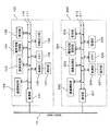
図1は、本発明の一実施形態による通信システムの一構成例を示すブロック図であり、各機能ブロックの電気的接続構成をも示している。図1において、100はプリンタ、200は電子スチルカメラであり、IEEE1394シリアルバスのケーブル(以下、「1394ケーブル」とも称す。)10を介して通信可能なように接続されている。
Hereinafter, embodiments of the present invention will be described with reference to the drawings.
FIG. 1 is a block diagram showing a configuration example of a communication system according to an embodiment of the present invention, and also shows an electrical connection configuration of each functional block. In FIG. 1,
各機器の構成について説明する。プリンタ100は、通信部101、通信補助部102、画像処理部103、着脱可能記録部104、表示部105、制御部106、操作部107、メモリ108および印刷出力部109により構成され、各ブロックは制御を行うためのコントロールバス110とデータを伝送するためのデータバス111とにより接続されている。
The configuration of each device will be described. The
通信部101は、IEEE1394規格に準拠した通信方式により1394ケーブル10を介して外部の機器(例えば、電子スチルカメラ200)等との間で通信を行うためのものである。通信補助部102は、IEEE1394規格準拠の通信方式にプリンタ100内部の情報を変換するためのものである。
The
画像処理部103は、1394ケーブル10を介してプリンタ100に送られてきたデータや、着脱可能記録部104に記録されているデータを印刷出力できるように、上記データに画像処理を施す。着脱可能記録部104は、プリンタ100に限らず、別の機器に接続してデータを記録したり、読み出したりすることも可能であり、表示部105は、ユーザーがプリンタ100を操作する際に操作の補助になる情報を提示する。
The
制御部106は、プリンタ100全体の制御を行う。操作部107は、ユーザーがプリンタ100を実際に操作するためのものであり、メモリ108は画像処理部103にて印刷出力用に画像処理が施されたデータを一時的に記録しておき、印刷出力部109は、画像処理が施されたデータを印刷出力する。
The
電子スチルカメラ200は、通信部201、通信補助部202、画像処理部203、着脱可能記録部204、表示部205、制御部206、操作部207、メモリ208および撮像部209により構成され、各ブロックは制御を行うためのコントロールバス210とデータを伝送するためのデータバス211とにより接続されている。
The electronic still
通信部201は、IEEE1394規格に準拠した通信方式により1394ケーブル10を介して外部の機器(例えば、プリンタ100)等との間で通信を行うためのものである。通信補助部202は、IEEE1394規格準拠の通信方式に電子スチルカメラ200内部の情報を変換するためのものである。
The
画像処理部203は、撮像部209によって得られたデータに画像処理を施し、画像として認識できる状態にする。着脱可能記録部204は、電子スチルカメラ200に限らず、別の機器に接続してデータを記録したり、読み出したりすることが可能であり、表示部205は、ユーザーが電子スチルカメラ200を操作する際に操作の補助になる情報を提示する。
The
制御部206は、電子スチルカメラ200全体の制御を行う。操作部207は、ユーザーが電子スチルカメラ200を実際に操作するためのものであり、メモリ208は画像処理が施されたデータを一時的に記録するためのものである。撮像部209は、被写体像を撮影し電気的信号として得るためのものである。
The
次に、1394シリアルバスを介して電子スチルカメラ200からプリンタ100に画像データを転送し、プリンタ100にて印刷出力する際の各機器の動作について説明する。
Next, the operation of each device when image data is transferred from the
電子スチルカメラ200にて、ユーザーが表示部205で被写体像を確認しながら操作部207によって撮影を促す操作を行うと、制御部206は被写体像を撮影するように撮像部209を制御する。撮像部209により得られた画像データは、データバス211を介してメモリ208に一時的に記録される。さらに、メモリ208に記録された画像データは、画像処理部203にて画像処理が施された後、データバス211を介して着脱可能記録部204にファイルとして記録される。
When the user performs an operation for prompting shooting with the
着脱可能記録部204に記録された画像データに係る画像は、ユーザーが操作部207により再生操作を行うことで表示部205に表示することも可能であるし、電子スチルカメラ200から着脱可能記録部204を切り離してPC等に接続することで再生(表示)することも可能である。
The image related to the image data recorded in the
また、着脱可能記録部204に記録された画像データは、通信部201を介して1394シリアルバス経由でプリンタ100に送信して印刷出力することも可能である。この場合には、電子スチルカメラ200は、データ伝送を保証するためにIEEE1394規格に準拠した通信方式で通信を行わなければならない。本実施形態では、AV/C Compatible Asynchronous Serial Bus Connections規格(1394 Trade Association)、およびAV/C Commands for Management of Asynchronous Serial Bus Connections規格(1394 Trade Association)を利用してデータ転送を行う。以下、上記二つの転送方法(規格)を総称して「アシンクロナスコネクション(Asynchronous Connection)」と称す。通信部201は、上記アシンクロナスコネクションを行う手段を有しており、これによりデータ転送が保証される。
The image data recorded in the
プリンタ100に転送し印刷する画像の画像データは、電子スチルカメラ200の表示部205に表示される着脱可能記録部204に記録された画像データの中から操作部207を用いて選択される。選択された画像データは、1394シリアルバス経由でプリンタ100に伝送されるが、画像データを伝送する前に、プリンタ100を制御するためのコマンドが電子スチルカメラ200からプリンタ100に送信される。
Image data of an image to be transferred to the
送信されたコマンドは、プリンタ100の通信部101を介して制御部106に転送され、制御部106はプリンタ100をデータ受信待ち状態に制御する。その後、選択された画像データが電子スチルカメラ200の通信部201を介してアシンクロナスコネクションによりプリンタ100に伝送される。データ受信待ち状態のプリンタ100は、電子スチルカメラ200から送信されてくる画像データを受信すると、データバス111を介してメモリ108に一時的に記録する。メモリ108に記録された画像データは、画像処理部103にて印刷出力用に画像処理が施され、印刷出力部109によって出力される。
The transmitted command is transferred to the
上述した説明は、電子スチルカメラ200からプリンタ100に画像データを伝送して印刷するプッシュモデルである。
以下に、プリンタ100が電子スチルカメラ200に記録された画像を選択して、1394シリアルバス経由で取得し印刷する際の動作について説明する。
The above description is a push model in which image data is transmitted from the
Hereinafter, an operation when the
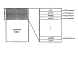
電子スチルカメラ200の通信補助部202は、着脱可能記録部204にファイルとして記録されている画像データに関するファイル情報を読み出し、所定のファイルシステムにマッピングを行う。通信補助部202により表現される上記ファイルシステムは、1394シリアルバスを介して外部の機器から参照することができる。すなわち、1394シリアルバスを介して接続された各機器は、通信補助部202を各機器に実装しておくことで、各機器における記録媒体の記録方式が異なっていたとしても1394シリアルバス上では同様のファイルシステムとして取り扱うことが可能になる。
The communication
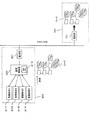
図2は、本実施形態における上記ファイルシステムの構成例を示す図である。なお、この図2において、図1に示したブロック等と同一の機能を有するブロック等には同一の符号を付し、重複する説明は省略する。 FIG. 2 is a diagram showing a configuration example of the file system in the present embodiment. In FIG. 2, blocks having the same functions as those shown in FIG. 1 are denoted by the same reference numerals, and redundant description is omitted.
電子スチルカメラ200にて撮影された画像が、上記図1に示した着脱可能記録部204に記録形式A2−1で記録されている。通信補助部202は、記録形式A2−1で記録されているファイル情報を、図2に示すような予め定められた形式の情報形態(ファイルフォーマット)に変換して、変換により得られたファイル情報2−5を内部メモリ2−6に一時的に記録しておく。
An image photographed by the
そして、プリンタ100の操作部107にて所定の操作を行い、電子スチルカメラ200が有するファイル情報を取得するためのコマンドをプリンタ100から電子スチルカメラ200に送信する。これにより、プリンタ100は、通信補助部202の内部メモリ2−6に保持するファイル情報2−5を1394シリアルバス経由で取得することができる。また、仮に記録形式A2−1とは異なる記録形式B2−2、記録形式C2−3、もしくは記録形式D2−4で電子スチルカメラ200の着脱可能記録部204にファイル情報が記録されていたとしても、プリンタ100は同一のファイルフォーマットのファイル情報2−5として認識することができる。
Then, a predetermined operation is performed on the
上述のようにして取得したファイル情報は、プリンタ100の表示部105に表示され、ユーザーは操作部107を用いて印刷したい画像を選択する。上記選択に応じて、プリンタ100は、選択された画像の画像データを取得するためのコマンドを電子スチルカメラ200に送信する。同時に、プリンタ100内部では、1394シリアルバス経由で画像データを受信し印刷するためにデータ受信待ち状態になる。
The file information acquired as described above is displayed on the
電子スチルカメラ200は、上記画像データの取得を要求するコマンドを受信すると、アシンクロナスコネクションによりプリンタ100に対して画像データの伝送を行う。プリンタ100は、電子スチルカメラ200からの画像データを受信すると、当該画像データをメモリ108に一時的に記録し、画像処理部103にて印刷出力用に画像処理を施した後、印刷出力部109によって出力する。
When the
次に、上記図1に示した着脱可能記録部104、204のような記録デバイス(記録媒体)に記録されたファイルヘのアクセス手段について説明する。
Next, means for accessing a file recorded on a recording device (recording medium) such as the
<ファイルシステムのデータ構造>
本実施形態における記録デバイスでは、指定されたファイルにアクセスする際にファイルパス(file_path)を用いる。上記ファイルパスは、可変長のデータであり、例えば、ルートディレクトリからのフルパス名である。また、上記ファイルパスでは、例えば、ディレクトリのデリミタとして”/”の文字(“5C16”)(下付の添え字“16”は16進数表記であることを示す。以下についても同様である。)を用いるとともに、ターミネータとしてNULL(ヌル)文字(“0016”)を用いる。
<Data structure of file system>
The recording device according to the present embodiment uses a file path (file_path) when accessing a specified file. The file path is variable length data, for example, a full path name from the root directory. In the above file path, for example, the character “/” (“5C 16 ”) (subscript “16” indicates a hexadecimal notation as a directory delimiter. The same applies to the following. ) And a NULL (“00 16 ”) character as a terminator.
上記ファイルパスのデータ長は、ファイルパス長(file_path_length)により示され、当該ファイルパス長には、最後のNULL文字の長さは含まれない。
上記ファイルパスデータおよびファイルパス長データは、後述するファイルアクセスコマンドセットにて使用される。
The data length of the file path is indicated by a file path length (file_path_length), and the file path length does not include the length of the last NULL character.
The file path data and the file path length data are used in a file access command set described later.
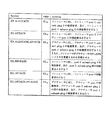
本実施形態における記録デバイスからファイルの情報を取得する側のデバイス(以下、「コントローラ」と称す。)は、ファイルの情報を取得するために、記録デバイスに対してファイルリストを要求する。上記ファイルリストは、上記ファイルリストを要求するコマンドのレスポンスとして、記録デバイスからコントローラに転送される。ここで、ファイルリストは、複数のディレクトリエントリと、各ディレクトリエントリが保持しているファイルあるいはディレクトリの情報とを含む。また、ファイルリストのディレクトリエントリは、例えばサイズが20バイトであり、図3に示すようなデータ構造を有する。 A device (hereinafter referred to as “controller”) that acquires file information from a recording device in the present embodiment requests a file list from the recording device in order to acquire file information. The file list is transferred from the recording device to the controller as a response to a command requesting the file list. Here, the file list includes a plurality of directory entries and information on files or directories held by the directory entries. Further, the directory entry of the file list is, for example, 20 bytes in size and has a data structure as shown in FIG.
図3は、本実施形態におけるディレクトリエントリのデータ構造の一例を示す図である。図3に示したディレクトリエントリの各フィールドは、例えば、DOS(disk operating system)−FAT(file allocation table)システムとして知られているデータ構造と同様のデータ構造を有している。しかしながら、上記図3に示したディレクトリエントリでは、DOS−FATシステムのようなカレントディレクトリおよび親ディレクトリ情報は保持していない。 FIG. 3 is a diagram showing an example of the data structure of the directory entry in the present embodiment. Each field of the directory entry shown in FIG. 3 has a data structure similar to, for example, a data structure known as a DOS (disk operating system) -FAT (file allocation table) system. However, the directory entry shown in FIG. 3 does not hold the current directory and parent directory information as in the DOS-FAT system.
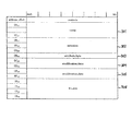
図3において、最初の11バイト(アドレスオフセット値“0016”〜“0A16”)のフィールドは、名前(name)フィールド301および拡張子(extension)フィールド302であり、ファイルの名前を示す。上記2つのフィールド301、302により、例えば、上述したDOS−FATシステムにおけるファイル名8文字と拡張子3文字とを形成することができる。上記記録デバイスに保持されているファイルの名前または拡張子が、上記2つのフィールド長よりも小さい場合には、例えば、パディングバイト(padding byte)が詰められる。上記パディングバイトの値は、例えば“2016”である。
In FIG. 3, the first 11 bytes (address offset values “00 16 ” to “0A 16 ”) are a
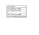
次の1バイト(アドレスオフセット値“0B16”)のフィールドは、属性(attribute_byte)フィールド303であり、ファイルの属性情報を示す。属性フィールド303は、図4に示すようなビットフィールドを含む。
The next 1-byte field (address offset value “0B 16 ”) is an attribute (attribute_byte)
図4は、属性フィールド303の構成を示す図であり、ディレクトリ(directory)ビット401は、当該ディレクトリエントリがサブディレクトリか否かを示す。例えば、ディレクトリビット401が“1”にセットされている時には、当該ディレクトリエントリはサブディレクトリである。また、リード・オンリ(read_only)ビット402は、当該ディレクトリエントリ内のファイルに対して読み出しのみが可能であり、書き込み/消去が不可能であるか否かを示す。例えば、リード・オンリビット402が“1”にセットされている時には、ファイルは読み出し専用である。なお、図4において、複数のイグノア(ignored)ビットは、当該記録デバイスがいかなる値を書き込んでも、コントローラに無視されるようになっている。
FIG. 4 is a diagram showing a configuration of the
図3に戻り、更新時間(modification_time)フィールド304(アドレスオフセット値“0C16”、“0D16”)、および更新日付(modification_date)フィールド305(アドレスオフセット値“0E16”、“0F16”)は、ファイルの最新更新日時を示す。また、ファイルサイズ(file_size)フィールド306(アドレスオフセット値“1016”〜“1316”)は、ファイル長(単位はバイト)を示す。 Returning to FIG. 3, the update time (modification_time) field 304 (address offset value “0C 16 ”, “0D 16 ”) and the update date (modification_date) field 305 (address offset value “0E 16 ”, “0F 16 ”) Indicates the latest update date and time of the file. A file size (file_size) field 306 (address offset values “10 16 ” to “13 16 ”) indicates a file length (in bytes).
本実施形態においては、複数の記録メディアと、当該記録メディア上の複数に分割されたいわゆるパーティションとを取り扱うことができる。上記記録メディアを、例えば「物理ボリューム」と称すると共に、上記パーティションを、例えば「論理ボリューム」と称する。 In the present embodiment, it is possible to handle a plurality of recording media and so-called partitions that are divided into a plurality of portions on the recording media. The recording medium is referred to as “physical volume”, for example, and the partition is referred to as “logical volume”, for example.
本実施形態では、上記物理ボリュームの指定を物理ボリューム番号(physical_volume_number)データにて行い、上記論理ボリュームの指定を論理ボリューム番号(logical_volume_number)データにて行う。コントローラは、上記物理ボリューム番号および論理ボリューム番号により記録デバイス上の特定エリアを指定することができる。上記物理ボリューム番号および論理ボリューム番号は、後述するファイルアクセスコマンドセットにて使用される。 In the present embodiment, the physical volume is designated by physical volume number (physical_volume_number) data, and the logical volume is designated by logical volume number (logical_volume_number) data. The controller can designate a specific area on the recording device by the physical volume number and the logical volume number. The physical volume number and the logical volume number are used in a file access command set described later.
上記物理ボリューム番号データは、例えば“0016”から“FE16”の値をとり、最初の物理ボリューム番号は“0016”の値をとる。“FF16”の値は、例えば特別であり、上記物理ボリューム番号値は後述するファイルアクセスコマンドセットに応じて意味付けが異なる。 The physical volume number data takes a value from “00 16 ” to “FE 16 ”, for example, and the first physical volume number takes a value “00 16 ”. The value “FF 16 ” is special, for example, and the physical volume number value has a different meaning depending on the file access command set described later.
上記論理ボリューム番号データは、例えば“0016”から“FE16”の値をとり、最初の論理ボリューム番号は“0016”の値をとる。“FF16”の値は、例えば特別であり、上記論理ボリューム番号値は後述するファイルアクセスコマンドセットに応じて意味付けが異なる。 The logical volume number data takes a value of “00 16 ” to “FE 16 ”, for example, and the first logical volume number takes a value of “00 16 ”. The value “FF 16 ” is special, for example, and the logical volume number value has a different meaning depending on a file access command set described later.
なお、本実施形態では、上記物理ボリューム番号および論理ボリューム番号の値が“FF16”の場合を例外としているが、“0016”から“FF16”の値をとるように構成しても良い。 In the present embodiment, the case where the values of the physical volume number and the logical volume number are “FF 16 ” is an exception, but it may be configured to take a value from “00 16 ” to “FF 16 ”. .
本実施形態の記録デバイスでは、記録メディアの交換を通知するのにメディア・カウント(media_generation_count)を用い、記録メディアが記録デバイスに挿入された時に、メディア・カウントの値が“1”だけ増加される。なお、記録デバイスが複数の物理ボリュームをサポートしている場合には、各物理ボリュームに対して固有のメディア・カウントを有する。 In the recording device of the present embodiment, the media count (media_generation_count) is used to notify the exchange of the recording medium, and when the recording medium is inserted into the recording device, the value of the media count is increased by “1”. . When the recording device supports a plurality of physical volumes, each recording volume has a unique media count.
電源投入等により記録デバイスが初期化された時には、上記メディア・カウントは初期化される。なお、メディア・カウントの初期値は、記録デバイスに固有の値であり、例えば、零であっても良く、乱数であっても良い。また、記録デバイスが、電源切断時等にフラッシュメモリやその他の不揮発性メモリ等にメディア・カウントの値を記憶させることができる場合には、次の初期化の際の初期値として記憶したメディア・カウントの値を使用するようにしても良い。本実施形態では、上記メディア・カウントは1バイトのデータであり、バスリセットが発生した場合にはメディア・カウントの値は保持されるようになっている。 When the recording device is initialized by turning on the power or the like, the media count is initialized. Note that the initial value of the media count is a value unique to the recording device, and may be, for example, zero or a random number. Also, if the recording device can store the media count value in flash memory or other non-volatile memory when the power is turned off, etc., the media / memory stored as the initial value at the next initialization A count value may be used. In the present embodiment, the media count is 1-byte data, and the media count value is held when a bus reset occurs.
コントローラは、記録デバイスに記録メデイアが挿入され、メディア・カウントの値が増加したことを検出すると、上述したファイルリストを再取得する。本実施形態における記録デバイスでは、記録メデイアの抜去によりメディア・カウントの値が増加することがないので、記録メディアの抜去により新たなファイルリストの取得を行う必要がなく、不要なトランザクションを発生させることがない。 When the controller detects that the recording medium is inserted into the recording device and the value of the media count is increased, the controller reacquires the file list described above. In the recording device according to the present embodiment, since the media count value does not increase when the recording medium is removed, it is not necessary to acquire a new file list by removing the recording medium, and an unnecessary transaction is generated. There is no.
<ファイルアクセスコマンドセット>
次に、本実施形態のファイルシステムに関するコマンドについて説明する。本実施形態では、コマンドを用いることで、ファイル属性の取得やファイルの転送などのファイルに関する様々な制御を行うことが可能である。
本実施形態のファイルシステムに関するコマンドは、例えば、IEEE1394規格で定義されているFCP(Function Control Protocol)を用いている。
<File access command set>
Next, commands related to the file system of this embodiment will be described. In the present embodiment, various commands relating to files such as file attribute acquisition and file transfer can be performed by using commands.
The command relating to the file system of the present embodiment uses, for example, FCP (Function Control Protocol) defined in the IEEE 1394 standard.
以下、図5を参照してFCPについて説明する。
図5は、FCPを説明するための概念図である。FCPは、1394シリアルバスを介して接続されたデバイスを制御するためにIEEE1394規格に基づいて設計されており、種々のコマンドセットとコマンドトランザクションとが、FCP上で利用可能である。また、FCPではコマンドおよびレスポンスを送信する際に、IEEE1394規格のアシンクロナスパケット(Asynchronous packet)が用いられる。
Hereinafter, FCP will be described with reference to FIG.
FIG. 5 is a conceptual diagram for explaining FCP. FCP is designed based on the IEEE 1394 standard to control devices connected via a 1394 serial bus, and various command sets and command transactions are available on the FCP. In FCP, when transmitting a command and a response, an IEEE1394 standard asynchronous packet is used.
FCPにおいて、他の(複数の)ノードを制御するノードを“コントローラ”と呼び、制御されるノードを“ターゲット”と呼ぶ。図5においては、500はコントローラ、510はターゲットとして動作するようになっている。 In FCP, a node that controls other node (s) is called a “controller”, and a controlled node is called a “target”. In FIG. 5, 500 operates as a controller and 510 operates as a target.
また、FCPにおいては、コントローラからターゲットに送られるFCPフレームを“コマンドフレーム”と呼び、ターゲットからコントローラに送られるFCPフレームを“レスポンスフレーム”と呼ぶ。上記コマンドフレームを受け取る準備をしたレジスタを“コマンドレジスタ”と呼び、上記レスポンスフレームを受け取る準備をしたレジスタを“レスポンスレジスタ”と呼ぶ。図5においては、501および502は、コントローラ500上のコマンドレジスタおよびレスポンスレジスタであり、511および512は、ターゲット510上のコマンドレジスタおよびレスポンスレジスタである。
In FCP, an FCP frame sent from the controller to the target is called a “command frame”, and an FCP frame sent from the target to the controller is called a “response frame”. A register prepared to receive the command frame is referred to as a “command register”, and a register prepared to receive the response frame is referred to as a “response register”. In FIG. 5, 501 and 502 are command registers and response registers on the
FCPフレームを用いて送出されるアシンクロナスパケットのデータ構造を図6に示す。
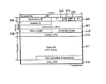
図6において、601はデスティネーションIDフィールド、602はトランザクション・ラベル(tl)フィールド、603はリトライコード(rt)フィールド、604はトランザクション・コード(tcode)フィールド、605はプライオリティ(pri)フィールド、606はソースIDフィールド、607はデスティネーションオフセットフィールド、608はデータ長フィールド、609は拡張トランザクション・コードフィールド、610はヘッダCRC(header_CRC)フィールド、611はデータフィールド(FCPフレーム)、612はデータCRC(data_CRC)フィールドである。上記アシンクロナスパケットは、例えば4バイト(32ビット、以下「クアッドレッド」と称す。)を単位とするデータパケットである。
FIG. 6 shows the data structure of an asynchronous packet transmitted using an FCP frame.
In FIG. 6, 601 is a destination ID field, 602 is a transaction label (tl) field, 603 is a retry code (rt) field, 604 is a transaction code (tcode) field, 605 is a priority (pri) field, and 606 is Source ID field, 607 is a destination offset field, 608 is a data length field, 609 is an extended transaction code field, 610 is a header CRC (header_CRC) field, 611 is a data field (FCP frame), and 612 is a data CRC (data_CRC) It is a field. The asynchronous packet is, for example, a data packet in units of 4 bytes (32 bits, hereinafter referred to as “quad red”).
図6に示したアシンクロナスパケットにおいて、最初の16ビットのフィールドが、デスティネーションIDフィールド601であり、受信側(送信先)のノードIDを示す。次の6ビットのフィールドが、トランザクション・ラベルフィールド602であり、各トランザクション固有のタグである。次の2ビットのフィールドが、リトライコードフィールド603であり、パケットがリトライを試みるか否かを指定する。
In the asynchronous packet shown in FIG. 6, the first 16-bit field is a
次の4ビットのフィールドが、トランザクション・コードフィールド604であり、パケットのフォーマットや実行しなければならないトランザクションのタイプを指定する。本実施形態では、例えば、このフィールドの値が“00012”(下付の添え字“2”は2進数表記であることを示す。以下についても同様である。)である、データブロックの書き込みリクエストのトランザクションを用いる。
The next 4-bit field is the
次の4ビットのフィールドが、プライオリティフィールド605であり、優先順位を指定する。本実施形態ではアシンクロナスパケットを用いているので、このフィールドの値は、例えば“00002”である。
The next 4-bit field is a
次の16ビットのフィールドが、ソースIDフィールド606であり、送信側(送信元)のノードIDを示す。次の48ビットのフィールドが、デスティネーションオフセットフィールド607であり、パケットの受信側ノードアドレスの下位48ビットがこのフィールドによって指定される。
The next 16-bit field is a
次の16ビットのフィールドが、データ長フィールド608であり、後述するデータフィールド611の長さをバイト単位で示す。次の16ビットのフィールドが、拡張トランザクション・コードフィールド609であり、本実施形態にて用いられるデータブロックの書き込みリクエストのトランザクションにおいては、この値は、例えば“000016”である。
The next 16-bit field is a
次の32ビットのフィールドが、ヘッダCRCフィールド610であり、パケットヘッダ(上述したデスティネーションIDフィールド601から拡張トランザクション・コードフィールド609まで)のエラー検出に用いられる。
The next 32-bit field is a
次の可変長のフィールドが、データフィールド611であり、後述するCTS(Command/Transaction Set)にて用いられるコマンドフレームおよびレスポンスフレームが詰められる。上記データフィールド611を「ペイロード」と称する。本実施形態では、上記データフィールド611にてクアッドレットの倍数に満たないビットには、“0”の値が詰められるようになっている。つまり、上記データ長フィールド608に格納されるデータ長がバイト(8ビット)単位で示されるとき、当該データ長フィールド608の値が“4”の倍数でない場合には、上記データフィールドは、クアッドレットを満たすまで“0016”の値のデータによって埋められる。
The next variable length field is a
最後の32ビットのフィールドが、データCRCフィールド612であり、上述したヘッダCRCフィールド610と同様に、上記データフィールド611のエラー検出に用いられる。
The last 32-bit field is a
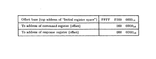
FCPにおいて、データブロックの書き込みリクエスト(“Write request for data block packet”)のペイロードであるデータフィールド611は、“FCPフレーム”と呼ばれ、コマンドフレームは、ターゲット上のコマンドレジスタに書き込まれるとともに、レスポンスフレームは、コントローラ上のレスポンスレジスタに書き込まれる。ここで、コマンドレジスタとレスポンスレジスタとは切り離されており、これらのレジスタのデスティネーションオフセットアドレスは、図7に示すようにFCPで規定されている。
In FCP, a
本実施形態においては、デスティネーションオフセットアドレスとして、“FFFF F000 0B0016”、および“FFFF F000 0D0016”を含むライトトランザクション(Write transaction)のみが許されている。 In this embodiment, as the destination offset address, "FFFF F000 0B00 16", and "FFFF F000 0D00 16" only write transactions containing (Write transaction) is allowed.
CTSは、コマンドセット、コマンドフィールドとレスポンスフィールドとの構造、およびコマンドとレスポンスとを送出する際に用いられるトランザクションの規則を指定したFCPフレームの一つのコンポーネントである。 CTS is one component of an FCP frame that specifies a command set, a structure of a command field and a response field, and a transaction rule used when sending a command and a response.
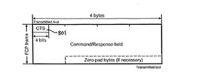
CTSで用いられるFCPフレームのデータ構造を図8に示す。
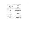
図8において、801はCTSフィールドである。CTSフィールド801は、4ビットのフィールドであり、CTSフィールド801の符号化の一例を図9に示す。本実施形態において、CTSフィールド801の値は、例えば“00002”を用いる。
FIG. 8 shows the data structure of an FCP frame used in CTS.
In FIG. 8,
図10は、本実施形態におけるコマンドフレームおよびレスポンスフレームのデータ構造を示す図である。
図10(a)は、コマンドフレームのデータ構造を示しており、図10(a)において、1001はコマンドタイプ(ctype)フィールド、1002はサブユニットタイプ(subunit_type)フィールド、1003はサブユニットID(subunit_ID)フィールド、1004はオペコード(opcode)である。また、図10(a)において、オペコード1004以降は、1バイト毎に(n+1)個(nは整数)のオペランド(operand[0]、operand[1]、…、operand[n])が続く。
FIG. 10 is a diagram illustrating a data structure of the command frame and the response frame in the present embodiment.
10A shows the data structure of the command frame. In FIG. 10A, 1001 is a command type (ctype) field, 1002 is a subunit type (subunit_type) field, and 1003 is a subunit ID (subunit_ID). A
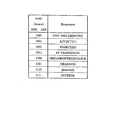
4ビットからなるコマンドタイプフィールド1001は、コマンドのタイプを示す。
図11は、コマンドタイプフィールド1001の値とコマンドタイプとの関係の一例を示す図である。
A
FIG. 11 is a diagram illustrating an example of the relationship between the value of the
図11に示すように、コマンドタイプフィールド1001の値が“00002”(コマンドタイプが“CONTROL”)のコマンドフレームは、コントローラが、ターゲットの制御を行うために用いる。制御内容は、後述するオペコードやオペランドによって指定される。また、コマンドタイプフィールド1001の値が“00012”(コマンドタイプが“STATUS”)のコマンドフレームは、コントローラが、ターゲットの現在の状態を問い合わせるために用いる。状態の指定は、後述するオペコードやオペランドによって行う。
As shown in FIG. 11, the command frame whose value in the
また、上記コマンドタイプフィールド1001の値が“00112”(コマンドタイプが“NOTIFY”)のコマンドフレームは、コントローラが、ターゲットの状態が変化したことをターゲットから通知させるために用いる。後述するオペコードやオペランドによって状態の指定を行うことは、上述した“STATUS”コマンドと同様である。
Further, the command frame whose value in the
さらに、コマンドタイプフィールド1001の値が“00102”あるいは“01002”(コマンドタイプが“SPECIFIC INQUIRY”あるいは“GENERAL INQUIRY”)のコマンドフレームは、同じオペコードを有する“CONTROL”コマンドが、ターゲットに実装されているか否かを確認するために用いる。ここで、“SPECIFIC INQUIRY”コマンドの場合には、オペコードと全てのオペランドとを指定しなければならないが、“GENERAL INQUIRY”コマンドの場合には、オペコードのみを指定する。これが、“SPECIFIC INQUIRY”コマンドと“GENERAL INQUIRY”コマンドとの相違点である。
Furthermore, a command frame with the same opcode is mounted on the target in the command frame with the
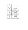
5ビットからなるサブユニットタイプフィールド1002と、3ビットからなるサブユニットIDフィールド1003とで、コマンドフレームが送られるサブユニット(subunit)を識別する。サブユニットは、AV/C Digital Interface Command Set General Specification(March 1998, 1394 Trade Association)規格(以下、「AV/Cコマンドセット規格」と称す。)等で定義されており、AVユニット(以下、単に「ユニット」とも称す。)の中で唯一つに識別されるとともに、首尾一貫した機能のセットを提供する仮想的なエントリーである。上記ユニットも、AV/Cコマンドセット規格にて同様に、定義されている。AVユニットは、1394シリアルバスに対して接続されているノードを有する電子デバイスを示す。
A 5-bit
上記AV/Cコマンドセット規格によれば、ユニットは、複数のサブユニットを有することができるようになっている。そこで、サブユニットタイプフィールド1002とサブユニットIDフィールド1003とは、1394インターフェースに接続されるユニット中のサブユニットを識別するためのアドレスを示すようになっている。サブユニットタイプフィールド1002の値とサブユニットのタイプとの関係の一例を図12に示す。
According to the AV / C command set standard, a unit can have a plurality of subunits. Therefore, the
上記サブユニットタイプフィールド1002とサブユニットIDフィールド1003とを総合して、「サブユニットアドレス」または「AV/Cアドレス」と称す。なお、上記サブユニットタイプフィールド1002の値が“111112”で、かつサブユニットIDフィールド1003の値が“0112”の場合には、サブユニットアドレスは、ユニットを示すようになっている。
The
本実施形態において、プリンタ100にコマンドフレームを送信する場合には、例えば、サブユニットタイプフィールド1002に“000102”の値を、サブユニットIDフィールド1003に“0002”の値を指定する。また、本実施形態において、電子スチルカメラ200のカメラサブユニットにコマンドフレームを送信する場合には、例えば、サブユニットタイプフィールド1002に“001112”の値を、サブユニットIDフィールド1003に“0002”の値を指定する。
In this embodiment, when a command frame is transmitted to the
さらに、本実施形態において、電子スチルカメラ200のファイルシステムを形成する通信補助部202は、図12におけるカメラ・ストレージ・サブユニット(Camera Storage Subunit)として動作する。このため、当該サブユニットにコマンドフレームを送信する場合には、例えば、サブユニットタイプフィールド1002に“010112”の値を、サブユニットIDフィールド1003に“0002”の値を指定する。
Furthermore, in the present embodiment, the communication
オペコード1004は、制御内容や後述するレスポンスフレームによって返される状態を定義する。オペコード1004の後に続く、オペランドの数と意味付けは、上述したコマンドタイプ、サブユニットタイプ、あるいはオペコードに応じて異なる。
The
図10(b)は、レスポンスフレームのデータ構造を示す図である。図10(b)において、図10(a)に示したフィールドと同一の機能を有するフィールドには同一の符号を付し、重複する説明は省略する。図10(b)において、1005はレスポンス(response)フィールドであり、レスポンスのタイプを示す。
図13は、レスポンスフィールド1005の値とレスポンスタイプとの関係の一例を示す図である。
FIG. 10B shows the data structure of the response frame. In FIG. 10B, fields having the same functions as those shown in FIG. 10A are denoted by the same reference numerals, and redundant description is omitted. In FIG. 10B,
FIG. 13 is a diagram illustrating an example of the relationship between the value of the
本実施形態では、ターゲットとなるサブユニットは、コマンドタイプ、サブユニットアドレス、オペコード、およびオペランドにより構成されるコントローラから送出されたコマンドフレームに対して、適切なレスポンスフレームを発生させてコントローラに返すようになっている。上記レスポンスフレームは、受信したコマンドフレームに応じたレスポンスタイプ、サブユニットアドレス、オペコード、およびオペランドにより構成される。 In this embodiment, the target subunit generates an appropriate response frame and returns it to the controller for the command frame sent from the controller configured by the command type, subunit address, opcode, and operand. It has become. The response frame includes a response type, a subunit address, an operation code, and an operand corresponding to the received command frame.
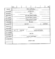
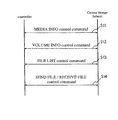
次に、本実施形態におけるカメラ・ストレージ・サブユニットのコマンドについて説明する。図14は、カメラ・ストレージ・サブユニットのコマンドと、カメラ・ストレージ・サブユニットのオペコード値との関係の一例を示す図である。 Next, commands of the camera / storage / subunit in this embodiment will be described. FIG. 14 is a diagram illustrating an example of a relationship between a command of the camera / storage subunit and an operation code value of the camera / storage subunit.
カメラ・ストレージ・サブユニットのコマンドは、コントローラからコマンドフレームとして発行される時、およびレスポンスフレームとしてコントローラに返される時に、共通のヘッダ領域(“common frame header”、以下、「共通フレームヘッダ」と称す。)を有する。制御コマンド(control command)(以下、単に「コマンド」とも称す。)における共通フレームヘッダのフォーマットを図15に示す。なお、図15においては、コマンドフレーム(command frame)における共通フレームヘッダのフォーマットを一例として示している。 When the command of the camera / storage / subunit is issued as a command frame from the controller and returned to the controller as a response frame, a common header area (hereinafter referred to as “common frame header”). .) FIG. 15 shows a format of a common frame header in a control command (hereinafter also simply referred to as “command”). In FIG. 15, the format of the common frame header in the command frame is shown as an example.
図15において、オペコード(opcode)には、上記図14に示したオペコード値が入力される。また、レスポンスフレーム(response frame)におけるオペコードには、コマンドフレームのオペコードの値と同じ値が入力される。 In FIG. 15, the opcode value shown in FIG. 14 is input to the opcode. In addition, the same value as the value of the operation code of the command frame is input to the operation code in the response frame.
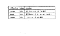
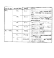
第0のオペランド(operand[0])は、1バイトのサブファンクション(subfunction)フィールドであり、制御コマンドの動作モードを指定する。上記制御コマンドの動作モードとサブファンクションフィールド値との関係を図16に示す。カメラ・ストレージ・サブユニットが無効なサブファンクションフィールド値が入力されたコマンドフレームを受信した場合には、“NOT IMPLEMENTED”のレスポンス値(レスポンスフィールドの値が“10002”)を有するレスポンスフレームを返す。また、レスポンスフレームにおける第0のオペランドには、コマンドフレームの第0のオペランドの値と同じ値が入力される。 The 0th operand (operand [0]) is a 1-byte subfunction field, and specifies the operation mode of the control command. FIG. 16 shows the relationship between the operation mode of the control command and the subfunction field value. If the camera storage sub-unit receives a command frame with an invalid subfunction field value, it returns a response frame with a response value of “NOT IMPLEMENTED” (response field value is “1000 2 ”) . Also, the same value as the value of the 0th operand of the command frame is input to the 0th operand of the response frame.
第1のオペランド(operand[1])は、1バイトのフィールドであり、固定値“FF16”が入力される。また、レスポンスフレームにおける第1のオペランドには結果コード(result code)が入力されて返される。上記結果コードの符号化の一例を図17に示す。ここで、カメラ・ストレージ・サブユニットが複数の理由により“REJECTED”レスポンスフレーム(レスポンスフィールドの値が“10102”)を返す場合には、図17に示した最も小さい値のデータが上記結果コードとして第1のオペランドに入力される。また、カメラ・ストレージ・サブユニットが“INTERIM”レスポンスフレーム(レスポンスフィールドの値が“11112”)を返す場合には、コントローラが発行した固定値と同じ“FF16”が結果コードとして入力される。 The first operand (operand [1]) is a 1-byte field, and a fixed value “FF 16 ” is input. A result code is input to the first operand in the response frame and returned. An example of the encoding of the result code is shown in FIG. Here, when the camera storage subunit returns a “REJECTED” response frame (response field value is “1010 2 ”) for a plurality of reasons, the data with the smallest value shown in FIG. As the first operand. Also, when the camera / storage subunit returns an “INTERIM” response frame (response field value is “1111 2 ”), “FF 16 ” that is the same as the fixed value issued by the controller is input as the result code. .
第2のオペランド(operand[2])は、物理ボリューム番号フィールドであり、物理ボリュームの指定を行う。第3のオペランド(operand[3])は、論理ボリューム番号フィールドであり、論理ボリュームの指定を行う。また、上述したようにコントローラがこれらのフィールドを用いないことを示す場合には、値“FF16”が入力される。 The second operand (operand [2]) is a physical volume number field that specifies a physical volume. The third operand (operand [3]) is a logical volume number field that specifies a logical volume. Further, as described above, when the controller indicates that these fields are not used, the value “FF 16 ” is input.
ここで、コマンドフレーム内の物理ボリューム番号フィールドの値または論理ボリューム番号フィールドの値が無効な場合には、カメラ・ストレージ・サブユニットは“REJECTED”レスポンスフレームあるいは“NOT IMPLEMENTED”レスポンスフレームを返す。このとき本実施形態では、例えば、以下のように動作する。 Here, when the value of the physical volume number field or the logical volume number field in the command frame is invalid, the camera storage subunit returns a “REJECTED” response frame or a “NOT IMPLEMENTED” response frame. At this time, in the present embodiment, for example, the following operation is performed.
・コマンドフレームで指定された物理ボリューム番号(物理ボリューム番号フィールド値)の記録メディアが存在しない場合には、カメラ・ストレージ・サブユニットは、結果コードとして“no media”(A016)の値が第1のオペランドに入力された“REJECTED”レスポンスフレームを返す。 • If there is no recording medium with the physical volume number (physical volume number field value) specified in the command frame, the camera storage subunit will have the value “no media” (A0 16 ) as the result code. Returns the “REJECTED” response frame input in the 1 operand.
・コマンドフレームで指定された論理ボリューム番号(論理ボリューム番号フィールド値)が物理ボリューム内に存在しない場合には、カメラ・ストレージ・サブユニットは、結果コードとして“invalid volume number”(9116)の値が第1のオペランドに入力された“REJECTED”レスポンスフレームを返す。 • If the logical volume number (logical volume number field value) specified in the command frame does not exist in the physical volume, the camera storage subunit will return the value of “invalid volume number” (91 16 ) as the result code. Returns a “REJECTED” response frame with the first operand input.
・カメラ・ストレージ・サブユニット内に存在しない物理ボリューム番号がコマンドフレームにより指定された場合には、カメラ・ストレージ・サブユニットは“NOT IMPLEMENTED”レスポンスフレームを返す。 • If a physical volume number that does not exist in the camera / storage / subunit is specified in the command frame, the camera / storage / subunit returns a “NOT IMPLEMENTED” response frame.
第4のオペランド(operand[4])は、メディア・カウントフィールドであり、記録メディアの交換を通知するために用いられる。コントローラが上記図14に示したメディア情報(“MEDIA INFO”)コマンドフレームおよびボリューム情報(“VOLUME INFO”)コマンドフレーム以外のコマンドフレームを発行する場合には、コントローラが保持しているメディア・カウントの値が上記メディア・カウントフィールドに設定される。また、コントローラがメディア情報コマンドフレーム、あるいはボリューム情報コマンドフレームを発行する場合には、上記メディア・カウントフィールドに“FF16”の値が設定される。 The fourth operand (operand [4]) is a media count field, which is used to notify the exchange of the recording media. When the controller issues a command frame other than the media information (“MEDIA INFO”) command frame and the volume information (“VOLUME INFO”) command frame shown in FIG. 14, the media count held by the controller is displayed. A value is set in the media count field. When the controller issues a media information command frame or a volume information command frame, a value “FF 16 ” is set in the media count field.
カメラ・ストレージ・サブユニットは、上記メディア情報コマンドフレーム以外のコマンドフレームに対し、自らが保持しているメディア・カウント値を第4のオペランドに設定したレスポンスフレームを返す。このとき、受信したコマンドフレームがメディア情報コマンドフレーム、ボリューム情報コマンドフレーム以外のコマンドフレームであった場合には、カメラ・ストレージ・サブユニットは、自らが保持しているメディア・カウント値とコマンドフレーム内のメディア・カウント値とを比較する。その結果、メディア・カウント値が異なる場合には、カメラ・ストレージ・サブユニットは、結果コードとして“invalid generation count”(9016)の値が第1のオペランドに入力された“REJECTED”レスポンスフレームを返す。 In response to a command frame other than the media information command frame, the camera storage subunit returns a response frame in which the media count value held by itself is set as the fourth operand. At this time, if the received command frame is a command frame other than the media information command frame and the volume information command frame, the camera / storage sub-unit stores the media count value held by itself and the command frame. Compare with the media count value. As a result, if the media count value is different, the camera storage sub-unit will send a “REJECTED” response frame with the result code “invalid generation count” (90 16 ) entered in the first operand. return.
また、通常は、コントローラがカメラ・ストレージ・サブユニットに任意の制御コマンドフレームを最初に送信する以前に、コントローラはボリューム情報コマンドフレームを発行して現在のメディア・カウント値を取得する。 Also, typically, before the controller first sends any control command frame to the camera storage subunit, the controller issues a volume information command frame to obtain the current media count value.
図18は、ファイルリストコマンド(FILE LIST control command)フレームのフォーマットを示す図である。
ファイルリストコマンドフレームにおいて、最初の6バイトのフィールドは、上述した共通フレームヘッダである。
FIG. 18 is a diagram showing the format of a file list command (FILE LIST control command) frame.
In the file list command frame, the first 6-byte field is the common frame header described above.
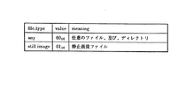
第5のオペランド(operand[5])は、ファイルタイプ(file_type)フィールドであり、取得するディレクトリエントリのファイル型を指定する。ファイルタイプフィールド値の定義を図19に示す。ファイルタイプフィールド値が“0016”(ファイルタイプ“any”)の場合には、返されるディレクトリエントリは任意のファイルあるいはディレクトリを含む。また、ファイルタイプフィールド値が“0116”(ファイルタイプ“still image”)の場合には、返されるディレクトリエントリは静止画像ファイルのみを含む。 The fifth operand (operand [5]) is a file type (file_type) field, and specifies the file type of the directory entry to be acquired. The definition of the file type field value is shown in FIG. When the file type field value is “00 16 ” (file type “any”), the returned directory entry includes an arbitrary file or directory. When the file type field value is “01 16 ” (file type “still image”), the returned directory entry includes only still image files.
第6のオペランド(operand[6])の下位2ビットは、属性(attribute)フィールドであり、取得するディレクトリエントリの型を指定する。属性フィールドの定義を図20に示す。
属性フィールドの下位ビット(“bit0”)が“1”に設定されている時には、カメラ・ストレージ・サブユニットはサブディレクトリを含んだディレクトリエントリを返す。一方、属性フィールドの下位ビットが“0”にクリアされている時には、カメラ・ストレージ・サブユニットはサブディレクトリを含んだディレクトリエントリを返さない。
The lower 2 bits of the sixth operand (operand [6]) are an attribute field that specifies the type of directory entry to be acquired. The definition of the attribute field is shown in FIG.
When the lower bit (“bit0”) of the attribute field is set to “1”, the camera storage subunit returns a directory entry including the subdirectory. On the other hand, when the lower bit of the attribute field is cleared to “0”, the camera storage subunit does not return the directory entry including the subdirectory.
また、属性フィールドの上位ビット(“bit1”)が“1”に設定されている時には、カメラ・ストレージ・サブユニットはファイルを含んだディレクトリエントリを返す。一方、属性フィールドの上位ビットが“0”にクリアされている時には、カメラ・ストレージ・サブユニットはファイルを含んだディレクトリエントリを返さない。
さらに、属性フィールドの双方のビットがともに“1”に設定されている時には、カメラ・ストレージ・サブユニットはファイルとサブディレクトリとを含んだディレクトリエントリを返す。
When the upper bit (“bit1”) of the attribute field is set to “1”, the camera storage subunit returns a directory entry including a file. On the other hand, when the upper bit of the attribute field is cleared to “0”, the camera storage subunit does not return the directory entry including the file.
Further, when both bits of the attribute field are set to “1”, the camera storage subunit returns a directory entry including a file and a subdirectory.
第7および第8のオペランド(operand[7]およびoperand[8])は、開始番号(start_number)フィールドを構成し、開始番号フィールドは、取得するディレクトリエントリの開始位置を指定する。開始番号フィールド値は、“0”から始まり、開始番号フィールド値により後述するページングパラメータを指定する。 The seventh and eighth operands (operand [7] and operand [8]) constitute a start number (start_number) field, and the start number field specifies the start position of the directory entry to be acquired. The start number field value starts from “0”, and a paging parameter to be described later is designated by the start number field value.
第9のオペランド(operand[9])の最上位ビット(MSB)は、エンド・オブ・リスト(“eol”:end of list)ビットである。レスポンスフレーム内のエンド・オブ・リストビットは、レスポンスフレーム内の最後のディレクトリエントリが、コマンドフレームで指定されたディレクトリの中の最後のディレクトリエントリであるか否かを示す。 The most significant bit (MSB) of the ninth operand (operand [9]) is an end of list (“eol”) bit. The end of list bit in the response frame indicates whether or not the last directory entry in the response frame is the last directory entry in the directory specified in the command frame.
具体的には、レスポンスフレームのエンド・オブ・リストビットの値が“0”にクリアされている場合には、レスポンスフレーム内の最後のディレクトリエントリが、コマンドフレームで指定されたディレクトリの最後のディレクトリエントリでないことを示す。一方、レスポンスフレームのエンド・オブ・リストビットの値が“1”に設定されている場合には、レスポンスフレーム内の最後のディレクトリエントリがコマンドフレームで指定されたディレクトリの最後のディレクトリエントリであることを示す。 Specifically, when the end of list bit value of the response frame is cleared to “0”, the last directory entry in the response frame is the last directory of the directory specified in the command frame. Indicates that it is not an entry. On the other hand, when the value of the end of list bit of the response frame is set to “1”, the last directory entry in the response frame is the last directory entry of the directory specified in the command frame. Indicates.
また、コントローラは、エンド・オブ・リストビットを“0”にクリアしてコマンドフレームを発行する。 The controller clears the end-of-list bit to “0” and issues a command frame.
第9のオペランドの下位5ビットは、エントリ数(number_of_entries)フィールドであり、コマンドフレームでは取得するディレクトリエントリ数を指定し、レスポンスフレームではレスポンスフレーム内に実際に含まれるディレクトリエントリ数を示す。コマンドフレーム内のエントリ数フィールド値と、その応答としてのレスポンスフレーム内のエントリ数フィールド値とは一致しないことがあり得るが、レスポンスフレーム内のエントリ数フィールド値は、それに対応するコマンドフレーム内のエントリ数フィールド値以下になることが保証されている。 The lower 5 bits of the ninth operand are the number of entries (number_of_entries) field. The command frame specifies the number of directory entries to be acquired, and the response frame indicates the number of directory entries actually included in the response frame. The entry number field value in the command frame may not match the entry number field value in the response frame as a response, but the entry number field value in the response frame corresponds to the entry in the command frame. Guaranteed to be less than a few field values.
上記開始番号フィールド、エンド・オブ・リストビット、およびエントリ数フィールドの値に基づいて、ページング機構が提供される。ここで、ページングは、カメラ・ストレージ・サブユニットがレスポンスフレームにより一度に返すことが可能なデータ長に制限があるため、複数のコマンド、レスポンストランザクションによりデータを授受する仕組みである。 A paging mechanism is provided based on the values of the start number field, end of list bit, and number of entries field. Here, paging is a mechanism in which data is exchanged by a plurality of commands and response transactions because there is a limit to the data length that can be returned at once by the response frame from the camera / storage subunit.
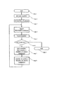
図21は、ページング動作を示すフローチャートである。なお、図21においては、コントローラにおけるファイルリスト取得時のページング動作の一例を示している。
図21において、ステップstep1にて、本実施形態におけるページング動作が開始されると、ステップstep2にて、コントローラは、上記開始番号の値を初期化する(例えば、開始番号の値に“0”を入力する)。
FIG. 21 is a flowchart showing the paging operation. FIG. 21 shows an example of a paging operation at the time of file list acquisition in the controller.
In FIG. 21, when the paging operation in the present embodiment is started in
次のステップstep3にて、コントローラは、上記エントリ数の値を初期化する。ここで、エントリ数の初期値は、コマンドフレームおよびレスポンスフレームの最大バイト数に応じて十分大きな値が入力される。例えば、コマンドフレームおよびレスポンスフレームの最大バイト数が256バイトの場合には、エントリ数の初期値として“128”等が入力される。
In the
次に、コントローラは、ステップstep4にて、ファイルリストコマンドフレームを送信し、ステップstep5にて、カメラ・ストレージ・サブユニットからのレスポンスフレームを受信する。コントローラは、レスポンスフレーム内の開始番号フィールド、エンド・オブ・リストビット、およびエントリ数フィールドの値をそれぞれ解析して、後に続く動作を決定する。
Next, the controller transmits a file list command frame in
まずステップstep6にて、エンド・オブ・リストビットが検査される。エンド・オブ・リストビットの値が“0”のときには、上述したようにディレクトリエントリが最後に達していないので、さらにディレクトリエントリを取得するために次のステップstep7に進む。ステップstep7では、開始番号フィールドの値と、レスポンスフレーム中のエントリ数フィールドの値とを加算して、新たな開始番号値を生成する。
First, at
次のステップstep8にて、レスポンスフレームから抽出したエントリ数フィールドの値をコマンドフレーム中のエントリ数フィールドに入力する。上述したように、レスポンスフレーム内のエントリ数フィールドの値は、それに対応するコマンドフレーム内のエントリ数フィールドの値以下となることが保証されているとともに、上記ステップstep3ではコマンドフレーム中のエントリ数フィールドの値に十分に大きな値が入力されているので、ステップstep8にてエントリ数フィールドに入力される値はレスポンスフレームにて返すことができる最大エントリ数である確率が高い。
In the
上記ステップstep4〜step8はループを構成しており、全てのディレクトリエントリを取得するまでステップstep4〜step8が実行される。一方、ステップstep6にて、エンド・オブ・リストビットの値が“1”のときには、ディレクトリエントリが最後に達しているので、ステップstep9に進み、ディレクトリエントリ取得動作を終了する。
上述したページング動作により、コントローラは着目したディレクトリに対して効率良くディレクトリエントリを取得することができる。
With the above-described paging operation, the controller can efficiently acquire a directory entry for the focused directory.
図18に戻り、第10および第11のオペランド(operand[10]およびoperand[11])は、リザーブ(reserved)フィールドであり、当該フィールドにいかなる値を設定してもカメラ・ストレージ・サブユニットに無視される。コントローラは、当該フィールドに、例えば“FF16”の値を設定してコマンドフレームを送信する。 Referring back to FIG. 18, the tenth and eleventh operands (operand [10] and operand [11]) are reserved fields, and any value set in the field can be stored in the camera storage subunit. It will be ignored. For example, the controller sets a value of “FF 16 ” in the field and transmits a command frame.
第12のオペランド(operand[12])は、リクエストパス長(request_path_length)フィールドであり、後に続くリクエストパス(request_path)フィールドのバイト長を示す。第13のオペランド(operand[13])以降は、可変長のリクエストパスフィールドであり、所望のディレクトリまたはファイルのパス名を指定する。上記リクエストパス長およびリクエストパスは、上述したファイルパス長およびファイルパスにそれぞれ相当する。 The twelfth operand (operand [12]) is a request path length (request_path_length) field, and indicates the byte length of the subsequent request path (request_path) field. The thirteenth operand (operand [13]) and thereafter are variable-length request path fields, which specify a desired directory or file path name. The request path length and the request path correspond to the above-described file path length and file path, respectively.
上述したファイルリストコマンドフレームに対する応答としてのレスポンスフレームにおいては、ファイルリスト(file_list)フィールドが上述したリクエストパスフィールドの領域に設定される。ファイルリストフィールドは、可変長フィールドであり、上述したディレクトリエントリが保持されている。ファイルリストフィールドには複数のディレクトリエントリを含むことが可能であり、ファイルリストフィールドに含まれるディレクトリエントリ数は、上述したレスポンスフレーム内のエントリ数フィールドにより指示される。また、図3に示したように、各ディレクトリエントリのサイズは20バイトである。 In a response frame as a response to the above-described file list command frame, a file list (file_list) field is set in the above-described request path field area. The file list field is a variable-length field and holds the directory entry described above. The file list field can include a plurality of directory entries, and the number of directory entries included in the file list field is indicated by the entry number field in the response frame described above. Also, as shown in FIG. 3, the size of each directory entry is 20 bytes.
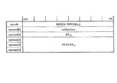
図22は、メディア情報コマンド(MEDIA INFO control command)フレームのフォーマットを示す図である。メディア情報コマンドは、カメラ・ストレージ・サブユニット内の記録メディアの情報を取得するために使用される。
メディア情報コマンドフレームにおいて、最初の6バイトのフィールドは、上述した共通フレームヘッダであり、物理ボリューム番号フィールド、論理ボリューム番号フィールド、およびメディア・カウントフィールドには固定値“FF16”をそれぞれ指定する。
FIG. 22 is a diagram showing a format of a media information command (MEDIA INFO control command) frame. The media information command is used to acquire information on a recording medium in the camera storage subunit.
In the media information command frame, the first 6-byte field is the above-described common frame header, and a fixed value “FF 16 ” is designated in the physical volume number field, logical volume number field, and media count field.
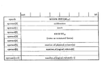
図23は、メディア情報コマンドフレームに対するレスポンスフレームのフォーマットを示す図であり、最初の6バイトのフィールドは共通フレームヘッダに対する応答部分である。
第5のオペランド(operand[5])は、物理ボリューム数(number_of_physical_volume)フィールドであり、カメラ・ストレージ・サブユニット内の記録メディア数、すなわち物理ボリューム数が入力される。なお、記録メディアが着脱可能であって記録メディアが挿入されていない時にも、当該記録メディアが物理ボリューム数に加えられている。
FIG. 23 is a diagram showing the format of a response frame for the media information command frame, and the first 6-byte field is a response portion for the common frame header.
The fifth operand (operand [5]) is a physical volume number (number_of_physical_volume) field, and the number of recording media in the camera storage subunit, that is, the number of physical volumes is input. Even when the recording medium is detachable and no recording medium is inserted, the recording medium is added to the number of physical volumes.
第6のオペランド(operand[6])以降は、論理ボリューム数(number_of_logical_volume)フィールドであり、物理ボリューム毎の論理ボリューム数が入力される。論理ボリューム数フィールドの総数は、上記物理ボリューム数フィールドの値に応じて異なり、物理ボリューム数フィールドの値がn(nは自然数)の場合には、第0の論理ボリューム数フィールド(number_of_logical_volume[0])から第(n−1)のボリューム数フィールド(number_of_logical_volume[n-1])までのn個の論理ボリューム数フィールドが存在する。なお、記録メディアが着脱可能であって記録メディアが挿入されていない時には、当該記録メディアに関連付けられている論理ボリューム数フィールドには“0016”の値が入力される。 After the sixth operand (operand [6]) is a logical volume number (number_of_logical_volume) field, and the number of logical volumes for each physical volume is input. The total number of logical volume fields differs depending on the value of the physical volume field. When the physical volume field is n (n is a natural number), the 0th logical volume field (number_of_logical_volume [0] ) To (n−1) th volume number field (number_of_logical_volume [n−1]), there are n logical volume number fields. When the recording medium is detachable and no recording medium is inserted, a value of “00 16 ” is input to the logical volume number field associated with the recording medium.
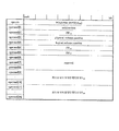
図24は、ファイル受信コマンド(RECEIVE FILE control command)フレームのフォーマットを示す図である。ファイル受信コマンドは、カメラ・ストレージ・サブユニット内の記録メディアにサブユニット・デスティネーションプラグ(subunit destination plug)から受信したファイルを記録するために使用される。 FIG. 24 is a diagram illustrating a format of a file reception command (RECEIVE FILE control command) frame. The file reception command is used to record a file received from a subunit destination plug on a recording medium in the camera storage subunit.
ファイル受信コマンドフレームにおいて、最初の6バイトのフィールドは、上述した共通フレームヘッダであり、物理ボリューム番号フィールドおよび論理ボリューム番号フィールドには記録される受信ファイルのボリュームを指定する。コントローラは、当該フィールドに“FF16”(“any available volume”)の値を設定して、カメラ・ストレージ・サブユニットが選択した任意の記録可能な物理ボリュームおよび論理ボリュームにファイルを記録することができる。そして、カメラ・ストレージ・サブユニットは、記録時に選択した物理ボリューム番号および論理ボリューム番号を、上記物理ボリューム番号フィールドおよび論理ボリューム番号フィールドにそれぞれ設定してレスポンスフレームを返す。 In the file reception command frame, the first 6-byte field is the common frame header described above, and the volume of the received file to be recorded is specified in the physical volume number field and the logical volume number field. The controller can set the value of “FF 16 ” (“any available volume”) in this field to record files to any recordable physical and logical volume selected by the camera storage subunit. it can. Then, the camera storage subunit sets the physical volume number and the logical volume number selected at the time of recording in the physical volume number field and the logical volume number field, respectively, and returns a response frame.
なお、コントローラがコマンドフレームの物理ボリューム番号フィールドに“FF16”の値を設定した場合には、カメラ・ストレージ・サブユニットは、コマンドフレーム内のメディア・カウントフィールドを無視するととも、選択した物理ボリュームのメディア・カウント値をメディア・カウントフィールドに設定したレスポンスフレームを返す。 If the controller sets a value of “FF 16 ” in the physical volume number field of the command frame, the camera storage sub-unit ignores the media count field in the command frame and selects the selected physical volume. Returns a response frame with the media count value set in the media count field.
第5〜第8のオペランド(operand[5]〜operand[8])の4バイトは、受信サイズ(receive_size)フィールドであり、記録するファイルのバイト数を指定する。コントローラが、記録するファイルのバイト数を予め決定できない場合には、コントローラは受信サイズフィールドに零(“00 00 00 0016”)の値を設定して、カメラ・ストレージ・サブユニットにファイルを記録させることができる。 Four bytes of the fifth to eighth operands (operand [5] to operand [8]) are a reception size (receive_size) field, and designate the number of bytes of a file to be recorded. If the controller cannot determine the number of bytes of the file to record in advance, the controller sets the value of zero (“00 00 00 00 16 ”) in the receive size field and records the file in the camera storage subunit. Can be made.
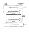
第9のオペランド(operand[9])は、デスティネーションプラグ(destination_plug)フィールドであり、ファイルデータを入力するためのサブユニット・デスティネーションプラグを指定する。通常、コントローラは、ファイル受信コマンドフレームを発行するのに先立ち、カメラ・ストレージ・サブユニットのサブユニット・デスティネーションプラグと、ユニットプラグ(unit plug)または同じユニット内の他のサブユニットのサブユニット・ソースプラグ(subunit source plug)とのコネクションを確立する。 The ninth operand (operand [9]) is a destination plug (destination_plug) field, and designates a subunit / destination plug for inputting file data. In general, prior to issuing a file reception command frame, the controller and the subunit / destination plug of the camera / storage / subunit and the unit plug (unit plug) or the subunit / subunit of another subunit within the same unit Establish a connection with the source plug.
ここで、コントローラがデスティネーションプラグフィールドにて指定するサブユニット・デスティネーションプラグが既に使用されている場合には、カメラ・ストレージ・サブユニットは、結果コードとして“busy”(“8016”)の値が第1のオペランドに入力された“REJECTED”レスポンスフレームを返す。 Here, if the subunit / destination plug specified by the controller in the destination plug field has already been used, the camera / storage / subunit will return “busy” (“80 16 ”) as the result code. Returns a “REJECTED” response frame with the value entered in the first operand.
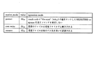
第10のオペランド(operand[10])は、受信モード(receive_mode)フィールドであり、第13のオペランド(operand[13])以降のファイルパスフィールドで指定されたファイルパス名と同じファイルパス名のファイルが既に存在するときの動作を指定する。受信モードフィールドの符号化の一例を図25に示す。 The tenth operand (operand [10]) is a reception mode (receive_mode) field, and a file having the same file path name as the file path name specified in the file path field after the thirteenth operand (operand [13]). Specifies what happens when an already exists. An example of encoding of the reception mode field is shown in FIG.
第11のオペランド(operand[11])は、ファイルタイプフィールドであり、受信されるファイルの型を指定する。ファイルタイプフィールドの符号化の一例を図26に示す。 The eleventh operand (operand [11]) is a file type field that specifies the type of the received file. An example of encoding of the file type field is shown in FIG.
ファイル受信コマンドフレームに対する応答としてのレスポンスフレームでは、例えば、上記受信サイズフィールド、デスティネーションプラグフィールド、受信モードフィールド、およびファイルタイプフィールドには、コマンドフレームと同じ値が入力されて返される。 In the response frame as a response to the file reception command frame, for example, the same value as the command frame is input and returned in the reception size field, the destination plug field, the reception mode field, and the file type field.
第12のオペランド(operand[12])は、ファイルパス長フィールド、第13のオペランド以降は可変長のファイルパスフィールドであり、上述したファイルパス長およびファイルパスに相当する。上述したように記録された結果のファイルパス名は、上記ファイルパスフィールドに設定され、レスポンスフレームによりコントローラに返される。なお、ファイル受信コマンドフレームに対して“REJECTED”レスポンスフレームが返されるときは、ファイルパスフィールドには零の値が設定される。 The twelfth operand (operand [12]) is a file path length field, and the thirteenth and subsequent operands are variable length file path fields, which correspond to the file path length and file path described above. The file path name of the result recorded as described above is set in the file path field and is returned to the controller by a response frame. When a “REJECTED” response frame is returned for the file reception command frame, a zero value is set in the file path field.
図27は、ファイル送信コマンド(SEND FILE control command)フレームのフォーマットを示す図である。ファイル送信コマンドフレームは、ファイルデータの送信トリガとして使用される。
ファイル送信コマンドフレームにおいて、最初の6バイトの領域は、上述した共通フレームヘッダである。また、第5〜第8のオペランド(operand[5]〜operand[8])には固定値“FF16”が設定される。
FIG. 27 is a diagram showing a format of a file transmission command (SEND FILE control command) frame. The file transmission command frame is used as a transmission trigger for file data.
In the file transmission command frame, the first 6-byte area is the above-described common frame header. A fixed value “FF 16 ” is set for the fifth to eighth operands (operand [5] to operand [8]).
第9のオペランド(operand[9])は、ソースプラグ(source_plug)フィールドであり、ファイルデータの送信に使用されるサブユニット・ソースプラグを指定する。通常、コントローラは、ファイル送信コマンドフレームを発行するのに先立ち、カメラ・ストレージ・サブユニットのサブユニット・ソースプラグと、ユニットプラグまたは同じユニット内の他のサブユニットのサブユニット・デスティネーションプラグとのコネクションを確立する。 The ninth operand (operand [9]) is a source plug (source_plug) field, which specifies a subunit / source plug used for transmission of file data. In general, prior to issuing a file transmission command frame, the controller performs a unit / source plug of a camera / storage / subunit and a unit / destination plug of a unit plug or another subunit in the same unit. Establish a connection.
ここで、カメラ・ストレージ・サブユニットがファイル送信コマンドフレームを受信したとき、当該コマンドフレームのソースプラグフィールドで指定されたサブユニット・ソースプラグが既に使用されている場合には、カメラ・ストレージ・サブユニットは、結果コードとして“busy”(“8016”)の値が第1のオペランドに入力された“REJECTED”レスポンスフレームを返す。 Here, when the camera / storage subunit receives the file transmission command frame, if the subunit / source plug specified in the source plug field of the command frame is already used, the camera / storage / subunit The unit returns a “REJECTED” response frame in which the value “busy” (“80 16 ”) is input to the first operand as a result code.
また、ファイル送信コマンドで指定されたサブユニット・ソースプラグに接続されているユニットプラグまたは同じユニット内の他のサブユニットのサブユニット・デスティネーションプラグが指定されたファイルを受信できない場合には、カメラ・ストレージ・サブユニットは、結果コードとして“invalid file type”(“A616”)の値が第1のオペランドに入力された“REJECTED”レスポンスフレームを返す。 If the unit plug connected to the subunit / source plug specified by the file transmission command or the subunit / destination plug of another subunit in the same unit cannot receive the specified file, the camera The storage subunit returns a “REJECTED” response frame in which the value of “invalid file type” (“A6 16 ”) is input to the first operand as a result code.
上述したファイル受信コマンドフレームと同様に、第12のオペランド(operand[12])はファイルパス長フィールド、第13のオペランド(operand[13])以降は可変長のファイルパスフィールドであり、上述したファイルパス長およびファイルパスに相当する。上述したように記録された結果のファイルパス名は、上記ファイルパスフィールドに設定され、レスポンスフレームによりコントローラに返される。なお、ファイル送信コマンドフレームに対して“REJECTED"レスポンスフレームが返されるときは、ファイルパスフィールドには零の値が設定される。 Similar to the file reception command frame described above, the twelfth operand (operand [12]) is a file path length field, and the thirteenth operand (operand [13]) and subsequent are variable length file path fields. Corresponds to path length and file path. The file path name of the result recorded as described above is set in the file path field and is returned to the controller by a response frame. When a “REJECTED” response frame is returned for the file transmission command frame, a zero value is set in the file path field.
図28は、ボリューム情報コマンド(VOLUME INFO control command)フレームのフォーマットを示す図であり、図29は、ボリューム情報コマンドフレームに対するレスポンスフレームのフォーマットを示す図である。ボリューム情報コマンドは、指定されたボリュームの情報を取得するために使用される。 FIG. 28 is a diagram showing the format of a volume information command (VOLUME INFO control command) frame, and FIG. 29 is a diagram showing the format of a response frame for the volume information command frame. The volume information command is used to acquire information on a specified volume.
上記図28に示したボリューム情報コマンドフレームにおいて、最初の6バイトのフィールドは、上述した共通フレームヘッダであり、物理ボリューム番号フィールドおよび論理ボリューム番号フィールドには、情報を取得する物理ボリュームおよび論理ボリュームをそれぞれ指定する。 In the volume information command frame shown in FIG. 28, the first 6-byte field is the common frame header described above, and the physical volume and logical volume from which information is acquired are displayed in the physical volume number field and the logical volume number field. Specify each.
第4のオペランド(operand[4])は、ボリューム情報コマンドフレームにおいては固定値“FF16”が設定され、レスポンスフレームにおいてはメディア・カウント値が設定される。 As the fourth operand (operand [4]), a fixed value “FF 16 ” is set in the volume information command frame, and a media count value is set in the response frame.
第5のオペランド(operand[5])は、ボリューム情報コマンドフレームにおいては固定値“FF16”が設定され、レスポンスフレームにおいては属性(attributes)フィールドである。属性フィールドは、指定されたボリュームの状態を示す属性がビットアサインされる。 The fifth operand (operand [5]) is set to a fixed value “FF 16 ” in the volume information command frame, and is an attributes field in the response frame. In the attribute field, an attribute indicating the state of the designated volume is bit-assigned.
属性フィールドのフォーマットを図30に示す。図30において、最上位ビットから6ビットのフィールドは、リザーブビットであり、当該領域に指定した値はカメラ・ストレージ・サブユニットにて無視される。最下位ビットから2ビット目のビット(“bit1”)は、書き込み禁止指示(write_protected)ビットであり、指定されたボリュームが書き込み禁止の場合には“1”に設定される。最下位ビット(“bit0”)は、読み出し専用指示(read_only_media)ビットであり、指定されたボリュームが読み出し専用の場合には、“1”に設定される。 The format of the attribute field is shown in FIG. In FIG. 30, the 6-bit field from the most significant bit is a reserved bit, and the value specified in this area is ignored by the camera storage subunit. The second bit (“bit1”) from the least significant bit is a write prohibition instruction (write_protected) bit, and is set to “1” when the specified volume is write protected. The least significant bit (“bit0”) is a read-only instruction (read_only_media) bit, and is set to “1” when the designated volume is read-only.
ボリューム情報コマンドフレームにおいて、第9〜第16のオペランド(operand[9]〜operand[16])および第17〜第24のオペランド(operand[17]〜operand[24])には、固定値“FF FF FF FF FF FF FF FF16”が設定される。
ボリューム情報コマンドフレームに対するレスポンスフレームにおいて、第9〜第16のオペランド(operand[9]〜operand[16])は、最大容量(maximum_capacity)フィールドであり、指定されたボリュームの最大容量がバイト単位で設定される。また、第17〜第24のオペランド(operand[17]〜operand[24])は、空き容量(free_space)フィールドであり、指定されたボリュームの現在の空き容量がバイト単位で設定される。
In the volume information command frame, the ninth to sixteenth operands (operand [9] to operand [16]) and the seventeenth to twenty-fourth operands (operand [17] to operand [24]) have a fixed value “FF”. FF FF FF FF FF FF FF 16 ”is set.
In the response frame for the volume information command frame, the ninth to sixteenth operands (operand [9] to operand [16]) are maximum capacity (maximum_capacity) fields, and the maximum capacity of the specified volume is set in bytes. Is done. The 17th to 24th operands (operand [17] to operand [24]) are free capacity (free_space) fields, and the current free capacity of the specified volume is set in bytes.
<ファイル転送>
次に、コントローラとカメラ・ストレージ・サブユニットとの間での標準的な通信手順について説明する。図31は、コントローラとカメラ・ストレージ・サブユニットとの間でのコマンドの発行手順の概要を示す図である。
<File transfer>
Next, a standard communication procedure between the controller and the camera storage subunit will be described. FIG. 31 is a diagram showing an overview of a command issuance procedure between the controller and the camera storage subunit.
まず、コントローラは、カメラ・ストレージ・サブユニットに対してメディア情報コマンドを発行して、カメラ・ストレージ・サブユニットが有する記録メディアのボリューム数の情報を取得する(S11)。コントローラは、メディア情報コマンドによりボリューム数の情報を取得した後、1つのボリュームを選択する。 First, the controller issues a media information command to the camera storage subunit to obtain information on the number of recording media volumes that the camera storage subunit has (S11). The controller selects one volume after obtaining the information on the number of volumes by the media information command.
コントローラは、選択したボリュームにアクセスする前にボリューム情報コマンドを発行して、カメラ・ストレージ・サブユニットから現在のメディア・カウント値を取得する(S12)。当該ボリューム情報コマンドにより取得した値は、コントローラが選択したボリュームにアクセスするための各コマンドのコマンドフレームを発行する際に、メディア・カウントフィールドに設定される。 The controller issues a volume information command before accessing the selected volume, and acquires the current media count value from the camera storage subunit (S12). The value acquired by the volume information command is set in the media count field when the command frame of each command for accessing the volume selected by the controller is issued.
その後、コントローラは、ファイルリストコマンドを発行して、カメラ・ストレージ・サブユニットからファイルリストを取得する(S13)。コントローラは、ファイルリストを取得した後、ファイル送信コマンドあるいはファイル受信コマンドを発行し、コントローラとカメラ・ストレージ・サブユニットとの間でのファイル転送を開始させる(S14)。 Thereafter, the controller issues a file list command to acquire a file list from the camera / storage / subunit (S13). After acquiring the file list, the controller issues a file transmission command or a file reception command to start file transfer between the controller and the camera / storage subunit (S14).
次に、カメラ・ストレージ・サブユニットからのファイル(データ)転送手順について説明する。上記図31に示した通信手順により、ファイルリストを取得したコントローラは、ファイル送信コマンドを発行してデータ送信要求を行う。
このとき、コントローラは、ファイル送信コマンドの発行に先立って、カメラ・ストレージ・サブユニットのサブユニット・ソースプラグと、送信先(受信側)の装置であるデスティネーションとの間に、例えば上述したアシンクロナスコネクション(Asynchronous Connection)により、コネクションを確立する。なお、上記デスティネーションはコントローラであっても良いし、他の装置であっても良い。
Next, a file (data) transfer procedure from the camera storage subunit will be described. The controller that has acquired the file list by the communication procedure shown in FIG. 31 issues a file transmission command to make a data transmission request.
At this time, prior to the issuance of the file transmission command, the controller, for example, the above-described asynchronous device between the subunit / source plug of the camera / storage / subunit and the destination (receiving side) device. Connection is established by connection (Asynchronous Connection). The destination may be a controller or another device.
図32は、カメラ・ストレージ・サブユニットからファイルを転送させる際のコマンドフローの一例を示す図であり、縦方向(T軸方向)は概念的な時間経過を示している。 FIG. 32 is a diagram showing an example of a command flow when transferring a file from the camera storage subunit, and the vertical direction (T-axis direction) shows a conceptual time passage.
図32において、例えばコントローラとカメラ・ストレージ・サブユニットとの間に、アシンクロナスコネクションによりコネクションを確立する(S21)。次に、コントローラは、カメラ・ストレージ・サブユニットに対してファイル送信コマンドを発行して(S22)、カメラ・ストレージ・サブユニットからのデータの転送(S23)を開始させる。本実施形態では、コントローラは、図32に示したように上記コネクションが確立されている間において、複数のファイル送信コマンドを発行して、複数のトランザクションを発生させることが可能である(S24、S25)。コントローラは、データ転送が終了すると上記ステップS21にて確立したコネクションを切断する(S26)。 In FIG. 32, for example, a connection is established by an asynchronous connection between the controller and the camera storage subunit (S21). Next, the controller issues a file transmission command to the camera storage subunit (S22), and starts data transfer from the camera storage subunit (S23). In the present embodiment, the controller can issue a plurality of file transmission commands and generate a plurality of transactions while the connection is established as shown in FIG. 32 (S24, S25). ). When the data transfer ends, the controller disconnects the connection established in step S21 (S26).
次に、カメラ・ストレージ・サブユニットにファイルを受信させる手順について説明する。図33は、カメラ・ストレージ・サブユニットにファイルを受信させる際のコマンドフローの一例を示す図であり、上記図32と同様に縦方向(T軸方向)は概念的な時間経過を示している。上記図31に示した通信手順により、ボリュームに関する情報を取得したコントローラは、ファイル受信コマンドを発行してファイルデータの受信要求を行う。 Next, a procedure for causing the camera storage subunit to receive a file will be described. FIG. 33 is a diagram showing an example of a command flow when a file is received by the camera storage sub-unit, and the vertical direction (T-axis direction) shows a conceptual time passage as in FIG. . The controller that has acquired the information on the volume by the communication procedure shown in FIG. 31 issues a file reception command to make a file data reception request.
このとき、コントローラは、ファイル受信コマンドの発行に先立って、カメラ・ストレージ・サブユニットのサブユニット・デスティネーションプラグと、送信元(送信側)の装置であるソースとの間にアシンクロナスコネクションによりコネクションを確立する(S31)。なお、上記ソースは、コントローラであっても良いし、他の装置であっても良く、例えば図33においては、コントローラをソースとしてコネクションを確立している。 At this time, prior to issuing the file reception command, the controller establishes a connection by an asynchronous connection between the subunit / destination plug of the camera / storage / subunit and the source which is the transmission source device. Establish (S31). The source may be a controller or another device. For example, in FIG. 33, a connection is established using the controller as a source.
次に、コントローラは、カメラ・ストレージ・サブユニットに対してファイル受信コマンドを発行して(S32)、カメラ・ストレージ・サブユニットにファイルデータの受信(S33)を開始させる。図33に示したように上記コネクションが確立している間において、コントローラは、複数のファイル受信コマンドを発行して、複数のファイルを受信させることが可能である(S34、S35)。コントローラは、ファイルデータ転送が終了すると上記ステップS31にて確立したコネクションを切断する(S36)。 Next, the controller issues a file reception command to the camera storage subunit (S32), and causes the camera storage subunit to start receiving file data (S33). As shown in FIG. 33, while the connection is established, the controller can issue a plurality of file reception commands to receive a plurality of files (S34, S35). When the file data transfer ends, the controller disconnects the connection established in step S31 (S36).
上述したファイル転送の手順において、コネクションは確立されているが、コントローラからファイル転送のトリガになるコマンド、例えばファイル送信コマンドあるいはファイル受信コマンドが発行されていないにもかかわらずファイルデータが送受信された場合には、カメラ・ストレージ・サブユニットは当該ファイルデータを破棄する。 In the file transfer procedure described above, a connection has been established, but file data has been sent / received even though a command that triggers file transfer from the controller, for example, a file transmission command or a file reception command has not been issued. In this case, the camera storage subunit discards the file data.
以上説明したように、データの送信側であるプロデューサノード(以下、「プロデューサ」と称す。)と、データの受信側であるコンシューマノード(以下、「コンシューマ」と称す。)とのコネクションを管理するコントローラノード(以下、「コントローラ」と称す。)が、プロデューサとコンシューマとを制御する場合には、コントローラは次の手順に従ってコマンドを発行する。
1)コントローラは、コネクションを確立するコマンドをコンシューマおよびプロデューサに発行する。
2)コントローラは、トリガコマンド(例えば、ファイル受信コマンド)をコンシューマに発行する。
3)コントローラは、コンシューマからのレスポンスを受け取った後、トリガコマンド(例えば、ファイル送信コマンド)をプロデューサに発行する。
As described above, the connection between the producer node (hereinafter referred to as “producer”) that is the data transmission side and the consumer node (hereinafter referred to as “consumer”) that is the data reception side is managed. When a controller node (hereinafter referred to as “controller”) controls a producer and a consumer, the controller issues a command according to the following procedure.
1) The controller issues a command to establish a connection to consumers and producers.
2) The controller issues a trigger command (for example, a file reception command) to the consumer.
3) After receiving the response from the consumer, the controller issues a trigger command (for example, a file transmission command) to the producer.
<アシンクロナスコネクション(Asynchronous Connection)>
上述したように本実施形態におけるファイルシステムでは、アシンクロナスコネクションにより、ファイルデータの転送およびファイル属性データの転送が行われる。アシンクロナスコネクションによりデータを送受信する通信システムは、例えば図34に示すように、データの送信側であるプロデューサ3401、データの受信側であるコンシューマ3402、およびプロデューサとコンシューマとのコネクションを管理するコントローラ3403から構成される。なお、図34においては、プロデューサ3401、コンシューマ3402、およびコントローラ3403をそれぞれ異なるノードとして示しているが、コントローラ3403を設けずに、プロデューサ3401がコントローラ3403の機能を有するようにしても良いし、コンシューマ3402がコントローラ3403の機能を有するようにしても良い。
<Asynchronous Connection>
As described above, in the file system according to the present embodiment, file data transfer and file attribute data transfer are performed by an asynchronous connection. As shown in FIG. 34, for example, a communication system that transmits and receives data through an asynchronous connection includes a
プロデューサ3401およびコンシューマ3402は、データの送受信を行うためのアシンクロナスプラグレジスタ(Asynchronous Plug Register)をそれぞれ所有する。上記アシンクロナスプラグレジスタは、図35に示すように構成されており、1つのアシンクロナス入力ポートレジスタ(iAPR:input Asynchronous Port Register)と、複数のアシンクロナス出力ポートレジスタ(oAPR:output Asynchronous Port Register)(図35に示した例においては、第1〜第14のアシンクロナス出力ポートレジスタ(oAPR[1]〜oAPR[14]))とで構成される。また、1つのアシンクロナス入力ポートレジスタおよび複数のアシンクロナス出力ポートレジスタは、IEEE1394インターフェースのアドレス空間にそれぞれ割り当てられる。
The
ここで、プロデューサとしての機能のみを有するノードは、アシンクロナス出力ポートレジスタだけを備え、コンシューマとしての機能のみを有するノードは、アシンクロナス入力ポートレジスタとデータ受信用のセグメントバッファ(segment buffer)とを備える。また、プロデューサおよびコンシューマの双方の機能を有するノードは、アシンクロナス入力ポートレジスタとアシンクロナス出力ポートレジスタとセグメントバッファとを備える。 Here, a node having only a function as a producer includes only an asynchronous output port register, and a node having only a function as a consumer includes an asynchronous input port register and a segment buffer for receiving data. A node having both functions of a producer and a consumer includes an asynchronous input port register, an asynchronous output port register, and a segment buffer.
ここで、プロデューサは、1つのコネクションで複数のコンシューマに対してデータを送信することができる場合には、そのデータ送信能力に応じて複数のアシンクロナス出力ポートレジスタを備え、1つのコンシューマにのみデータを送信することができない場合には、1つのアシンクロナス出力ポートレジスタだけを備えていれば良い。 Here, when a producer can transmit data to a plurality of consumers with one connection, the producer has a plurality of asynchronous output port registers according to the data transmission capability, and the data is transmitted to only one consumer. If transmission is not possible, it is sufficient to provide only one asynchronous output port register.
また、複数のコネクションを同時に形成することができるノードは、上記図35に示したアシンクロナスプラグレジスタを複数備える。このようにノードによっては複数のアシンクロナスプラグを有する場合もあり、各アシンクロナスプラグはプラグID(plug_id)により識別される。 A node capable of simultaneously forming a plurality of connections includes a plurality of asynchronous plug registers shown in FIG. Thus, some nodes may have a plurality of asynchronous plugs, and each asynchronous plug is identified by a plug ID (plug_id).
例えば、プロデューサ3401がライトトランザクションによりコンシューマ3402が備えるセグメントバッファに画像データ等を書き込むとする。このとき、書き込まれるデータをフレームと呼び、フレームのサイズがセグメントバッファのサイズより大きい場合には、複数回のセッションに分けて書き込みが行われる。この1回のセッションで書き込まれるデータをセグメントと呼ぶ。
For example, it is assumed that the
コントローラ3403は、コンシューマ3402のノードID、コネクションに使用するコンシューマ3402のプラグアドレス、プラグ番号等の情報をプロデューサ3401に対して送信する。同様に、コントローラ3403は、プロデューサ3401のノードID、コネクションに使用するプロデューサ3401のプラグアドレス、プラグ番号等の情報をコンシューマ3402に対して送信する。コントローラ3403からの情報を受信したプロデューサ3401およびコンシューマ3402は、受信した情報に基づいてデータの通信を開始し、プロデューサ3401からコンシューマ3402にデータが送信される。
The
上述したコントローラ3403からプロデューサ3401あるいはコンシューマ3402に対しての通信、およびプロデューサ3401とコンシューマ3402との間でのデータの通信は、アシンクロナストランザクションを用いて行われる。このアシンクロナストランザクションに用いられるパケットフォーマットは、上記図6に示したデータ構造と同様である。
The communication from the
上記アシンクロナスコネクションに用いられるコマンドフレームのフォーマットは、例えば図36に示すように構成されている。なお、コントローラ3403からプロデューサ3401あるいはコンシューマ3402に送信されるコマンドフレームと、プロデューサ3401あるいはコンシューマ3402からコントローラ3403に送信されるレスポンスフレームとは、同じフォーマットである。
The format of the command frame used for the asynchronous connection is configured as shown in FIG. 36, for example. Note that the command frame transmitted from the
オペコード(opcode)3601は、コマンドの種類を示しており、アシンクロナスコネクションのコマンドフレームであることを示すコード値“2616”が設定される。
サブファンクションフィールド3602は、当該コマンドによりプロデューサやコンシューマが行う動作(プラグリソースの確保、コネクションの設定/解除等)を指定する。サブファンクションフィールドの符号化について図37に示す。
An
The
なお、以下の説明では、アシンクロナスコネクションコマンド(ASYNCHRONOUS CONNECTION control command)フレームは、サブファンクションフィールドに基づいて呼称する。例えば、アシンクロナスコネクションコマンドフレームのサブファンクションフィールドの値が“E116”(EX_ALLOCATE)の場合には、“EX_ALLOCATE”コマンドフレームと称する。 In the following description, an asynchronous connection command (ASYNCHRONOUS CONNECTION control command) frame is called based on a subfunction field. For example, when the value of the sub-function field of the asynchronous connection command frame is “E1 16 ” (EX_ALLOCATE), it is referred to as an “EX_ALLOCATE” command frame.
ステータス(status)フィールド3603は、コマンド実行結果の状態を表すフィールドであり、レスポンスフレームにおいてデータが設定され、コントローラに状態が通知される。
The
プラグID(plug_id)フィールド3604は、コネクションに使用するプラグ番号を指定する。プラグIDフィールドの符号化の一例を図38に示す。図38において、値“BF16”は特別であり、コントローラが、カメラ・ストレージ・サブユニットのようなアシンクロナスコネクションをサポートしたデバイスに対して、現在使用していないプラグIDを用いてコネクションを確立するように指示するために使用される。
A plug ID (plug_id)
プラグオフセット(plug_offset)フィールド3605は、42ビットのフィールドであり、プラグの先頭アドレス(図35に示したアシンクロナス入力ポートレジスタに相当するアドレス)が設定される。
The plug offset (plug_offset)
ポートID(port_id)フィールド3606は、プラグ内のどのポートが選択されているかを示す。ポートIDフィールドの符号化の一例を図39に示す。図39において、コンシューマポート(Consumer Port[0])は、図35に示したアシンクロナス入力ポートレジスタ(iAPR)に対応し、第1〜第14のプロデューサポート(Producer Port[1]〜Producer Port[14])は、図35に示した第1〜第14のアシンクロナス出力ポート(oAPR[1]〜oAPR[14])にそれぞれ対応する。また、値“0F16”は特別であり、コントローラが、カメラ・ストレージ・サブユニットのようなアシンクロナスコネクションをサポートしたデバイスに対して、現在使用していないプロデューサポートを用いてコネクションを確立するように指示するために使用される。
A port ID (port_id)
したがって、コネクションに使用されるポートレジスタのオフセットアドレスは、例えば次式(1)により計算される。
(オフセットアドレス)=(plug_offset)≪6|(port_id)≪2 …(1)
ここで、上記式(1)において、“≪”は左ビットシフト演算を示し、“|”はビット毎の論理和(OR)演算を示す(以下についても同様である。)。
Therefore, the offset address of the port register used for the connection is calculated by the following equation (1), for example.
(Offset address) = (plug_offset) << 6 | (port_id) << 2 (1)
Here, in the above formula (1), “<<” indicates a left bit shift operation, and “|” indicates a bitwise logical OR operation (the same applies to the following).
ポートビット(port_bits)フィールド3607は、選択されているポートの能力を示す。ポートビットフィールドの符号化の一例を図40に示す。なお、図40において“X”は、考慮しないビット(Don't Care)であることを示す。
接続ノードID(connected_node_id)フィールド3608は、コネクションを設定する相手のノード(以下、「接続ノード」と称す。)を示す。コントローラは、コンシューマに対しては接続されるプロデューサのノードIDを設定してコマンドフレームで通知し、プロデューサに対しては接続されるコンシューマのノードIDを設定してコマンドフレームで通知する。
A port bits (port_bits)
A connected node ID (connected_node_id)
接続プラグオフセット(connected_plug_offset)フィールド3609は、接続ノードが有するプラグのアドレスを示す。
接続ポートID(connected_port_ID)フィールド3610は、コネクションに使用する接続ノードのポート番号を示す。
A connected plug offset (connected_plug_offset)
A connection port ID (connected_port_ID)
したがって、接続ノードのポートレジスタのオフセットアドレスは、次式(2)により計算される。
(オフセットアドレス)
=(connected_plug_offset)≪6|(connected_port_id)≪2 …(2)
Therefore, the offset address of the port register of the connection node is calculated by the following equation (2).
(Offset address)
= (Connected_plug_offset) << 6 | (connected_port_id) << 2 (2)
接続ポートビット(connected_port_bits)フィールド3611は、接続ノードのポートの能力を示す。
接続プラグID(connected_plug_id)フィールド3612は、コネクションに使用される接続ノードのプラグ番号を示す。
The connected port bits (connected_port_bits)
A connected plug ID (connected_plug_id)
排他制御(ex:exclusive)ビット3613は、コントローラが、内部コネクションとユニットから他のユニットへの接続との双方の制御に関して、他のコントローラを排除することを指定するビットである。
The exclusive control (ex: exclusive)
具体的には、排他制御ビット3613が“1”に設定されたアシンクロナスコネクションコマンドフレームを受け入れたターゲットノード(コントローラからのコマンドフレームを受信するノード)は、その後に発行され、受信したアシンクロナスコネクションコマンドフレームを調べ、受信したアシンクロナスコネクションコマンドフレームを発行したコントローラのノードIDと、排他制御ビット3613が“1”に設定されたアシンクロナスコネクションコマンドフレームを発行したコントローラのノードIDとが一致するか否かを検出する。その結果、ノードIDが不一致の場合には、ターゲットノードは受信したコマンドフレームに対して“REJECTED”レスポンスフレームを返す。
Specifically, the target node that received the asynchronous connection command frame in which the
また、排他制御ビット3613が“1”に設定されたアシンクロナスコネクションコマンドフレームは、次の場合にターゲットノードに受けつけられる。
・指定されたプラグがコンシューマのプラグの場合
・指定されたプロデューサのプラグが使用されていない場合
上述の場合には、ターゲットノードは、当該アシンクロナスコネクションコマンドフレームを発行したコントローラに対して、“ACCEPTED”レスポンスフレームを返す。
Also, the asynchronous connection command frame in which the
-When the specified plug is a consumer plug-When the specified producer plug is not used In the above case, the target node "ACCEPTED" to the controller that issued the asynchronous connection command frame. Returns a response frame.
コネクションカウント(connection_count)フィールド3614は、コンシューマのポートがいくつのプロデューサポートに接続されているかを示す。
ライトインターバル(write_interval)フィールド3615は、プロデューサがコンシューマのセグメントバッファにライトトランザクションを行う際のトランザクションの最小間隔を示す。
A connection count (connection_count)
A write interval (write_interval)
リトライカウント(retry_count)フィールド3616は、シリアルバストランザクションに失敗した場合に必要になるリトライ(再実行)回数の値を示す。リトライカウントフィールドの値は、コンシューマからのレスポンスフレームで設定される。
サブユニットタイプ(subunit_type)フィールド3617とサブユニットID(subunit_id)フィールド3618とで、ソースまたはデスティネーションになるサブユニットを指定する。サブユニットタイプフィールド3617とサブユニットIDフィールド3618の定義は、上述したサブユニットアドレスと同様である。
サブユニットプラグ(subunit_plug)フィールド3619は、データを授受するための入出力プラグであるサブユニットプラグ番号を指定する。
A retry count (retry_count)
A subunit type (subunit_type)
A subunit plug (subunit_plug)
次に、上述したアシンクロナスコネクションにおけるコネクション確立手順について説明する。図41は、アシンクロナスコネクションにおけるコネクション確立手順を示す図である。
図41において、4100はプロデューサ、4101はプロデューサ4100が有する第1のサブユニット、4102はソースプラグ、4103はプロデューサポート、4110はコントローラ、4120はコンシューマ、4121はコンシューマ4120が有する第2のサブユニット、4122はデスティネーションプラグ、4123はコンシューマポートである。
Next, a connection establishment procedure in the above-described asynchronous connection will be described. FIG. 41 is a diagram showing a connection establishment procedure in the asynchronous connection.
In FIG. 41, 4100 is a producer, 4101 is a first subunit of the
図41に示すように、本実施形態では、コントローラ4110は、まず、“EX_ALLOCATE”コマンド(EX_ALLOCATE control command)フレームをコンシューマ4120に対して発行する(1a)。このとき、図41に示した例では、コンシューマ4120内における第2のサブユニット4121のデスティネーションプラグ4122とコンシューマポート4123との内部コネクションが確立される。
As shown in FIG. 41, in the present embodiment, the
なお、デスティネーションプラグ4122とコンシューマポート4123との内部コネクションは、最初の“EX_ALLOCATE”コマンドフレームの発行後、後述する“EX_ATTACH”コマンド(EX_ATTACH control command)フレームが発行されるまでの間、当該内部コネクションが変更されないように排他的にロックされる。
The internal connection between the
上記図37に示したように、“EX_ALLOCATE”コマンドフレームは、アシンクロナスコネクションにおけるコンシューマポートの取得要求、サブユニット・デスティネーションプラグの取得要求、およびコンシューマポートとサブユニット・デスティネーションプラグとの間の接続要求を行う。コンシューマ4120は、サブユニットプラグIDとコンシューマポートのアドレスとを、上記“EX_ALLOCATE”コマンドフレームに対する“EX_ALLOCATE”レスポンスフレームとしてコントローラ4110に返す(1b)。
As shown in FIG. 37 above, the “EX_ALLOCATE” command frame includes a consumer port acquisition request, a subunit / destination plug acquisition request, and a connection between the consumer port and the subunit / destination plug in an asynchronous connection. Make a request. The
次に、コントローラ4110は、“EX_ALLOCATE_ATTACH”コマンド(EX_ALLOCATE_ATTACH control command)フレームをプロデューサ4100に対して発行し(2a)、サブユニット・ソースプラグの取得要求、プロデューサポートの取得要求、およびサブユニット・ソースプラグとプロデューサポートとの接続要求を行う。
Next, the
これにより、プロデューサ4100内における第1のサブユニット4101のソースプラグ4102とプロデューサポート4103との内部コネクションが確立される。また、プロデューサ4100は、上記“EX_ALLOCATE_ATTACH”コマンドフレームに対する“EX_ALLOCATE_ATTACH”レスポンスフレームをコントローラ4110に返す(2b)。
As a result, an internal connection between the
さらに、コントローラ4110は、“EX_ATTACH”コマンド(EX_ATTACH control command)フレームをコンシューマ4120に対して発行し(3a)、プロデューサポート4103とコンシューマポート4123との接続要求を行う。コンシューマ4120は、上記“EX_ATTACH”コマンドフレームに対する“EX_ATTACH”レスポンスフレームをコントローラ4110に返す(3b)。
Further, the
コンシューマ4120は、プロデューサ4100内のアシンクロナス出力ポートレジスタを更新して受信準備が終了したことを示す(4)。なお、プロデューサポート4103は、コンシューマ4120がプロデューサ4100内のアシンクロナス出力ポートレジスタを更新するまでの間、インアクティブ状態(非動作状態)に留まる。
The
上述のようにしてコネクションの確立手順に従って動作することにより、本実施形態では、第1のサブユニット4101と第2のサブユニット4121との間でのアシンクロナスコネクションが確立される。
By operating according to the connection establishment procedure as described above, an asynchronous connection is established between the
次に、上述したアシンクロナスコネクションにおけるコネクション切断手順について説明する。図42は、アシンクロナスコネクションにおけるコネクション切断手順を示す図である。なお、この図42において、図41に示したブロック等と同一の機能を有するブロック等には同一の符号を付し、重複する説明は省略する。 Next, a connection disconnection procedure in the above-described asynchronous connection will be described. FIG. 42 is a diagram showing a connection disconnection procedure in the asynchronous connection. In FIG. 42, blocks having the same functions as those shown in FIG. 41 are denoted by the same reference numerals, and redundant description is omitted.
図42に示すように、まず、コントローラ4110が“EX_DETACH”コマンド(EX_DETACH control command)フレームをコンシューマ4120に対して発行し(1a’)、コネクション切断手順が開始される。当該“EX_DETACH”コマンドフレームは、コネクションカウント値を減少させる。
As shown in FIG. 42, first, the
コンシューマ4120が、上記“EX_DETACH”コマンドフレームに対する応答として、コントローラ4110に返す“EX_DETACH”レスポンスフレーム(1b’)にて通知されるコネクションカウント値が零であるときには、コンシューマ4120が滞りなくコネクション切断手順に入ったことを示す。
When the connection count value notified in the “EX_DETACH” response frame (1b ′) returned to the
一方、上記“EX_DETACH”レスポンスフレームにて通知されるコネクションカウント値が零でないときには、コンシューマ4120は、まだ少なくとも1つのコネクションを有していることを示す。コネクションカウント値が零でない場合には、コントローラ4110は、後述する“EX_DETACH_RELEASE”コマンド(EX_DETACH_RELEASE control command)フレームを発行しないようになっている。
On the other hand, when the connection count value notified in the “EX_DETACH” response frame is not zero, it indicates that the
上述のように、上記“EX_DETACH”レスポンスフレームにて通知されるコネクションカウント値が零のとき、コンシューマ4120内の第2のサブユニット4121のデスティネーションプラグ4122とコンシューマポート4123とがインアクティブ状態になったままである。このインアクティブ状態のとき、コンシューマポート4123は、プロデューサ4100からのレジスタ更新、およびセグメントバッファへの書き込みを受け付ける。
As described above, when the connection count value notified in the “EX_DETACH” response frame is zero, the
次に、コントローラ4110は、“EX_DETACH_RELEASE”コマンドフレームをプロデューサ4100に対して発行し、(2a’)、プロデューサ4100内の第1のサブユニット4101のソースプラグ4102とプロデューサポート4103とのコネクションが切断される。また、プロデューサ4100は、上記“EX_DETACH_RELEASE”コマンドフレームに対する“EX_DETACH_RELEASE”レスポンスフレームをコントローラ4110に返す(2b’)。
Next, the
最後に、コントローラ4110は、“EX_RELEASE”コマンド(EX_RELEASE control command)フレームをコンシューマ4120に対して発行し(3a’)、コンシューマ4120内における内部コネクションが切断される。コンシューマ4120は、上記“EX_RELEASE”コマンドフレームに対する“EX_RELEASE”レスポンスフレームをコントローラ4110に返す(3b’)。
Finally, the
上述のようにしてコネクションの切断手順に従って動作することにより、本実施形態では、第1のサブユニット4101と第2のサブユニット4121との間でのアシンクロナスコネクションが切断される。
By operating according to the disconnection procedure as described above, in this embodiment, the asynchronous connection between the
以上、説明したように本実施形態によれば、アシンクロナスコネクションによりコネクションを確立するための既存のコマンドに加え、ユニット(プロデューサやコンシューマ)内のサブユニットプラグ(サブユニット・ソースプラグ、サブユニット・デスティネーションプラグ)を指定するためのフィールドを拡張して追加する。これにより、ユニット間におけるアシンクロナスコネクション、およびユニット内でのサブユニットプラグとユニットが備えるポートとの間におけるコネクションを単一のコマンドにより、同時に接続あるいは切断することができ、簡単な接続手順で、高速なデータ転送が可能であるとともに、データ転送の確実性が保証できる通信システムを実現することができる。 As described above, according to the present embodiment, in addition to the existing command for establishing the connection by the asynchronous connection, the subunit plug (subunit / source plug, subunit destination) in the unit (producer or consumer) is also provided. Expand the field for specifying the (Nation plug). As a result, asynchronous connections between units, and connections between subunit plugs within the units and the ports provided in the units can be connected or disconnected simultaneously with a single command. It is possible to realize a communication system capable of performing reliable data transfer and ensuring the reliability of data transfer.
また、アシンクロナスコネクションにおける排他制御ビットを設けることで、当該排他制御ビットの値に応じて、ユニット内部でのコネクションと、ユニットから他のユニットへの接続との双方の制御に関して他のコントローラを排除し、効率良く排他制御を行うことができる。 In addition, by providing an exclusive control bit in the asynchronous connection, other controllers are excluded for controlling both the connection within the unit and the connection from the unit to another unit according to the value of the exclusive control bit. Therefore, exclusive control can be performed efficiently.
なお、上述したアシンクロナスコネクションコマンドにおいては、AV/C Commands for Management of Asynchronous Serial Bus Connection規格と同じオペコード値(“2616”)を用いているが、他の任意の値を用いても良い。 In the above-described asynchronous connection command, the same opcode value (“26 16 ”) as that of the AV / C Commands for Management of Asynchronous Serial Bus Connection standard is used, but any other value may be used.
[他の実施形態]
本発明は、単一の機器からなる装置にも適用可能であるとともに、例えば、ホストコンピュータ、インターフェース機器、リーダ、プリンタなどの複数の機器から構成されるシステムにも適用可能である。
また、上述した実施形態の機能を実現するべく各種のデバイスを動作させるように、該各種デバイスと接続された装置あるいはシステム内のコンピュータに対し、上記実施形態の機能を実現するためのソフトウェアのプログラムコードを供給し、そのシステムあるいは装置のコンピュータ(CPUあるいはMPU)に格納されたプログラムに従って上記各種デバイスを動作させることによって実施したものも、本発明の範疇に含まれる。
[Other Embodiments]
The present invention can be applied to an apparatus including a single device, and can also be applied to a system including a plurality of devices such as a host computer, an interface device, a reader, and a printer.
Also, a software program for realizing the functions of the above-described embodiment for a computer in an apparatus or a system connected to the various devices so that the various devices are operated to realize the functions of the above-described embodiments. What was implemented by supplying the code and operating the various devices according to a program stored in the computer (CPU or MPU) of the system or apparatus is also included in the scope of the present invention.
また、この場合、上記ソフトウェアのプログラムコード自体が上述した実施形態の機能を実現することになり、そのプログラムコード自体、およびそのプログラムコードをコンピュータに供給するための手段、例えばかかるプログラムコードを格納した記録媒体は本発明を構成する。かかるプログラムコードを記憶する記録媒体としては、例えばフレキシブルディスク、ハードディスク、光ディスク、光磁気ディスク、CD−ROM、磁気テープ、不揮発性のメモリカード、ROM(プログラムROM、EPROM、EEPROMなど)等を用いることができる。 In this case, the program code of the software itself realizes the functions of the above-described embodiments, and the program code itself and means for supplying the program code to the computer, for example, the program code is stored. The recording medium constitutes the present invention. As a recording medium for storing the program code, for example, a flexible disk, a hard disk, an optical disk, a magneto-optical disk, a CD-ROM, a magnetic tape, a nonvolatile memory card, a ROM (program ROM, EPROM, EEPROM, etc.), etc. are used. Can do.
また、コンピュータが供給されたプログラムコードを実行することにより、上述の実施形態の機能が実現されるだけでなく、そのプログラムコードがコンピュータにおいて稼働しているOS(オペレーティングシステム)あるいは他のアプリケーションソフト等と共同して上述の実施形態の機能が実現される場合にもかかるプログラムコードは本発明の実施形態に含まれることは言うまでもない。 Further, by executing the program code supplied by the computer, not only the functions of the above-described embodiments are realized, but also the OS (operating system) or other application software in which the program code is running on the computer, etc. It goes without saying that the program code is also included in the embodiment of the present invention even when the functions of the above-described embodiment are realized in cooperation with the embodiment.
さらに、供給されたプログラムコードがコンピュータの機能拡張ボードやコンピュータに接続された機能拡張ユニットに備わるメモリに格納された後、そのプログラムコードの指示に基づいてその機能拡張ボードや機能拡張ユニットに備わるCPU等が実際の処理の一部または全部を行い、その処理によって上述した実施形態の機能が実現される場合にも本発明に含まれることは言うまでもない。 Further, after the supplied program code is stored in the memory provided in the function expansion board of the computer or the function expansion unit connected to the computer, the CPU provided in the function expansion board or function expansion unit based on the instruction of the program code Needless to say, the present invention includes a case where the functions of the above-described embodiment are realized by performing part or all of the actual processing.
10 ケーブル
100 プリンタ
101、201 通信部
102、202 通信補助部
103、203 画像処理部
104、204 着脱可能記録部
105、205 表示部
106、206 制御部
107、207 操作部
108、208 メモリ
109 印刷出力部
110、210 コントロールバス
111、211 データバス
200 電子スチルカメラ
209 撮像部
10
Claims (35)
任意の制御データを出力する制御手段を備え、
上記送信ノードは、上記シリアルバスを介してデータを送信するための送信手段と、
上記送信手段にデータを出力可能な出力手段を有するとともに、上記制御手段からの制御データにより制御可能な所定の機能を有する機能動作手段と、
上記送信手段と上記出力手段との接続状態を制御する通信路制御手段とを備え、
上記制御データは、単一の制御命令を用いて送信可能な上記送信手段と上記出力手段との接続状態を制御するための制御データを含むことを特徴とする通信システム。 A communication system in which a transmission node that transmits data and a reception node that receives data transmitted from the transmission node are connected via a serial bus capable of transmitting and receiving serial data,
Comprising control means for outputting arbitrary control data;
The transmission node includes a transmission means for transmitting data via the serial bus;
A function operation means having a predetermined function capable of being controlled by control data from the control means, and having an output means capable of outputting data to the transmission means;
Communication path control means for controlling the connection state between the transmission means and the output means,
The communication data, wherein the control data includes control data for controlling a connection state between the transmission means and the output means that can be transmitted using a single control command.
上記送信手段は、上記記録手段に記録されたデータを送信可能であることを特徴とする請求項1〜3の何れか1項に記載の通信システム。 The functional operation means is a recording means for recording data,
The communication system according to claim 1, wherein the transmission unit is capable of transmitting data recorded in the recording unit.
任意の制御データを出力する制御手段を備え、
上記受信ノードは、上記シリアルバスを介してデータを受信するための受信手段と、
上記受信手段で受信したデータを入力可能な入力手段を有するとともに、上記制御手段からの制御データにより制御可能な所定の機能を有する機能動作手段と、
上記受信手段と上記入力手段との接続状態を制御する通信路制御手段とを備え、
上記制御データは、単一の制御命令を用いて送信可能な上記受信手段と上記入力手段との接続状態を制御するための制御データを含むことを特徴とする通信システム。 A communication system in which a transmission node that transmits data and a reception node that receives data transmitted from the transmission node are connected via a serial bus capable of transmitting and receiving serial data,
Comprising control means for outputting arbitrary control data;
The receiving node includes receiving means for receiving data via the serial bus;
A function operating unit having an input unit capable of inputting data received by the receiving unit and having a predetermined function that can be controlled by control data from the control unit;
Communication path control means for controlling a connection state between the receiving means and the input means,
The communication system, wherein the control data includes control data for controlling a connection state between the receiving means and the input means that can be transmitted using a single control command.
上記送信ノードは、上記制御データの一部により制御可能であるとともに、データを出力するための出力手段をそれぞれ備えた所定の機能を有するn個(nは自然数)の機能動作手段と、
上記シリアルバスを介してアシンクロナス転送によりデータを送信するための送信手段とを具備し、
上記受信ノードは、上記シリアルバスを介してアシンクロナス転送により上記データを受信するための受信手段を具備し、
上記制御ノードは、単一のデータ送信により上記出力手段と上記送信手段との間のデータ送信路を確保するためのデータを含む上記制御データを上記送信ノードに送信することを特徴とする通信システム。 A communication system in which a control node that transmits arbitrary control data, a transmission node that receives the control data, and a reception node are connected via a serial bus for transmitting and receiving serial data,
The transmission node is controllable by a part of the control data, and has n (n is a natural number) function operation means each having a predetermined function each having an output means for outputting data,
Transmission means for transmitting data by asynchronous transfer via the serial bus,
The receiving node comprises receiving means for receiving the data by asynchronous transfer via the serial bus;
The control node transmits the control data including data for securing a data transmission path between the output unit and the transmission unit to the transmission node by a single data transmission. .
上記送信ノードは、上記シリアルバスを介してアシンクロナス転送によりデータを送信するための送信手段を具備し、
上記受信ノードは、上記制御データの一部により制御可能であるとともに、データを入力するための入力手段をそれぞれ備えた所定の機能を有するm個(mは自然数)の機能動作手段と、
上記シリアルバスを介してアシンクロナス転送により上記データを受信するための受信手段とを具備し、
上記制御ノードは、単一のデータ送信により上記入力手段と上記受信手段との間のデータ受信路を確保するためのデータを含む上記制御データを上記受信ノードに送信することを特徴とする通信システム。 A communication system in which a control node that transmits arbitrary control data, a transmission node that receives the control data, and a reception node are connected via a serial bus for transmitting and receiving serial data,
The transmission node includes transmission means for transmitting data by asynchronous transfer via the serial bus,
The receiving node is controllable by a part of the control data and has m (m is a natural number) functional operation means having a predetermined function each having an input means for inputting data;
Receiving means for receiving the data by asynchronous transfer via the serial bus,
The control node transmits the control data including data for securing a data reception path between the input unit and the reception unit to the reception node by a single data transmission. .
上記送信ノードは、データを記録するための記録手段と、
上記記録手段に記録されているデータを上記シリアルバスを介してアシンクロナス転送により送信するための送信手段とを具備し、
上記受信ノードは、上記送信ノードから送信されたデータを受信するための受信手段を具備し、
上記制御データは、単一のデータ送信により上記記録手段と上記送信手段との論理的な接続を行うための制御データを含むことを特徴とする通信システム。 A communication system in which a control node that transmits arbitrary control data, a transmission node that receives the control data, and a reception node are connected via a serial bus for transmitting and receiving serial data,
The transmission node includes a recording means for recording data;
Transmission means for transmitting the data recorded in the recording means by asynchronous transfer via the serial bus,
The receiving node comprises receiving means for receiving data transmitted from the transmitting node,
The communication system, wherein the control data includes control data for performing a logical connection between the recording means and the transmission means by a single data transmission.
上記送信ノードは、ファイルシステムを具備するとともに、当該ファイルシステムを上記シリアルバスを介してアシンクロナス転送により上記受信ノードに提供し、
上記制御データは、単一のデータ送信により上記ファイルシステムとの論理的な接続を行うための制御データを含むことを特徴とする通信システム。 A communication system in which a control node that transmits arbitrary control data, a transmission node that receives the control data, and a reception node are connected via a serial bus for transmitting and receiving serial data,
The transmission node includes a file system, and provides the file system to the reception node by asynchronous transfer via the serial bus.
The communication system, wherein the control data includes control data for logical connection with the file system by a single data transmission.
上記シリアルバスを介してデータを送信するための送信手段と、
上記送信手段にデータを出力可能な出力手段を有するとともに、制御データに基づいて制御可能な所定の機能を有する機能動作手段と、
上記送信手段と上記出力手段との接続状態を、単一の制御命令を用いて送信された制御データに基づいて制御可能な通信路制御手段とを備えることを特徴とする端末装置。 A terminal device connected to a receiving node for receiving data via a serial bus capable of transmitting and receiving serial data,
A transmission means for transmitting data via the serial bus;
A function operating means having an output means capable of outputting data to the transmission means and having a predetermined function which can be controlled based on the control data;
A terminal device comprising: a communication path control unit capable of controlling a connection state between the transmission unit and the output unit based on control data transmitted using a single control command.
上記シリアルバスを介してデータを受信するための受信手段と、
上記受信手段で受信したデータを入力可能な入力手段を有するとともに、制御データに基づいて制御可能な所定の機能を有する機能動作手段と、
上記受信手段と上記入力手段との接続状態を、単一の制御命令を用いて送信された制御データに基づいて制御可能な通信路制御手段とを備えることを特徴とする端末装置。 A terminal device connected to a transmission node that transmits data via a serial bus capable of transmitting and receiving serial data,
Receiving means for receiving data via the serial bus;
A function operating means having an input means capable of inputting data received by the receiving means and having a predetermined function that can be controlled based on the control data;
A terminal device comprising: a communication path control unit capable of controlling a connection state between the receiving unit and the input unit based on control data transmitted using a single control command.
上記送信ノードが備える、所定の機能を有する機能動作手段からデータを出力するための出力手段と、上記シリアルバスを介してデータを外部に送信するための送信手段との接続状態を、単一の制御命令を用いて送信された制御データに基づいて制御することを特徴とする通信システムの制御方法。 A control method of a communication system in which a transmission node that transmits data and a reception node that receives data transmitted from the transmission node are connected via a serial bus capable of transmitting and receiving serial data,
The connection state of the output means for outputting data from the functional operation means having a predetermined function provided in the transmission node and the transmission means for transmitting the data to the outside via the serial bus is a single state. A control method for a communication system, characterized in that control is performed based on control data transmitted using a control command.
上記受信ノードが備える、所定の機能を有する機能動作手段にデータを入力するための入力手段と、上記シリアルバスを介してデータを外部から受信するための受信手段との接続状態を、単一の制御命令を用いて送信された制御データに基づいて制御することを特徴とする通信システムの制御方法。 A control method of a communication system in which a transmission node that transmits data and a reception node that receives data transmitted from the transmission node are connected via a serial bus capable of transmitting and receiving serial data,
The connection state between the input means for inputting data to the function operation means having a predetermined function and the reception means for receiving data from the outside via the serial bus is provided in the reception node. A control method for a communication system, characterized in that control is performed based on control data transmitted using a control command.
Priority Applications (1)
| Application Number | Priority Date | Filing Date | Title |
|---|---|---|---|
| JP2003354142A JP2005123739A (en) | 2003-10-14 | 2003-10-14 | COMMUNICATION SYSTEM, TERMINAL DEVICE, COMMUNICATION SYSTEM CONTROL METHOD, RECORDING MEDIUM, AND PROGRAM |
Applications Claiming Priority (1)
| Application Number | Priority Date | Filing Date | Title |
|---|---|---|---|
| JP2003354142A JP2005123739A (en) | 2003-10-14 | 2003-10-14 | COMMUNICATION SYSTEM, TERMINAL DEVICE, COMMUNICATION SYSTEM CONTROL METHOD, RECORDING MEDIUM, AND PROGRAM |
Publications (2)
| Publication Number | Publication Date |
|---|---|
| JP2005123739A true JP2005123739A (en) | 2005-05-12 |
| JP2005123739A5 JP2005123739A5 (en) | 2006-11-30 |
Family
ID=34612217
Family Applications (1)
| Application Number | Title | Priority Date | Filing Date |
|---|---|---|---|
| JP2003354142A Pending JP2005123739A (en) | 2003-10-14 | 2003-10-14 | COMMUNICATION SYSTEM, TERMINAL DEVICE, COMMUNICATION SYSTEM CONTROL METHOD, RECORDING MEDIUM, AND PROGRAM |
Country Status (1)
| Country | Link |
|---|---|
| JP (1) | JP2005123739A (en) |
Cited By (1)
| Publication number | Priority date | Publication date | Assignee | Title |
|---|---|---|---|---|
| WO2009128158A1 (en) * | 2008-04-17 | 2009-10-22 | パイオニア株式会社 | Control device, control method, control program, and network system |
-
2003
- 2003-10-14 JP JP2003354142A patent/JP2005123739A/en active Pending
Cited By (3)
| Publication number | Priority date | Publication date | Assignee | Title |
|---|---|---|---|---|
| WO2009128158A1 (en) * | 2008-04-17 | 2009-10-22 | パイオニア株式会社 | Control device, control method, control program, and network system |
| JPWO2009128158A1 (en) * | 2008-04-17 | 2011-08-04 | パイオニア株式会社 | Control device, control method, control program, and network system |
| JP5050098B2 (en) * | 2008-04-17 | 2012-10-17 | パイオニア株式会社 | Control device, control method, control program, and network system |
Similar Documents
| Publication | Publication Date | Title |
|---|---|---|
| US6498598B2 (en) | Imaging device system, control method for the system, imaging device, control device, control method for the imaging device, control method for the control device, and storage medium | |
| JP2002016613A (en) | Electronic equipment, electronic equipment system, and communication control method | |
| TW541812B (en) | Electronic equipment, and method for controlling state of physical layer circuit thereof | |
| JP4027189B2 (en) | Information processing system, information processing apparatus, information processing method, program, and storage medium | |
| US6963938B2 (en) | Information processing apparatus and method therefor | |
| JP2001119410A (en) | Processing method in the self-identification phase | |
| KR100311707B1 (en) | Data communication system, data communication method, data communication apparatus, and digital interface | |
| US6457079B1 (en) | Communication apparatus with means for allocating alternate designation information to each function unit, and communication system with said two communication apparatuses | |
| US7177959B2 (en) | Information signal processing apparatus and method | |
| JP2005123739A (en) | COMMUNICATION SYSTEM, TERMINAL DEVICE, COMMUNICATION SYSTEM CONTROL METHOD, RECORDING MEDIUM, AND PROGRAM | |
| JP3943722B2 (en) | Data transfer apparatus, data transfer system and method, image processing apparatus, and recording medium | |
| KR20010007376A (en) | Controlling device, communication system and controlling method | |
| JPH10164113A (en) | Data communication system, apparatus and method | |
| US7167940B2 (en) | Data processing method, data processing apparatus, communications device, communications method, communications protocol and program | |
| US20020067741A1 (en) | Information control method, information processing apparatus, and information control system | |
| JP3977051B2 (en) | Communication apparatus and control method | |
| JP3897773B2 (en) | Communication method and communication apparatus | |
| JP4143205B2 (en) | Data communication system | |
| KR100297060B1 (en) | Protocol interface method | |
| JP2000299710A (en) | Data communication system, data communication device, file management method, and storage medium | |
| JP4095384B2 (en) | Information processing system, information processing apparatus, information processing method, program, and storage medium | |
| KR100577147B1 (en) | method for controlling device in bus system | |
| EP1028383A2 (en) | Data communication system, device, method and storage medium | |
| JP2000049833A (en) | Data transfer device, data transfer system and method, image processing device, and recording medium | |
| JP2005176266A (en) | Image processing apparatus, control apparatus, control system, image processing apparatus, control method for control apparatus, and control program |
Legal Events
| Date | Code | Title | Description |
|---|---|---|---|
| A521 | Written amendment |
Free format text: JAPANESE INTERMEDIATE CODE: A523 Effective date: 20061013 |
|
| A621 | Written request for application examination |
Free format text: JAPANESE INTERMEDIATE CODE: A621 Effective date: 20061013 |
|
| A977 | Report on retrieval |
Free format text: JAPANESE INTERMEDIATE CODE: A971007 Effective date: 20081111 |
|
| A131 | Notification of reasons for refusal |
Free format text: JAPANESE INTERMEDIATE CODE: A131 Effective date: 20081209 |
|
| A521 | Written amendment |
Free format text: JAPANESE INTERMEDIATE CODE: A523 Effective date: 20090206 |
|
| A02 | Decision of refusal |
Free format text: JAPANESE INTERMEDIATE CODE: A02 Effective date: 20090224 |