JP2005123749A - Imaging device - Google Patents
Imaging device Download PDFInfo
- Publication number
- JP2005123749A JP2005123749A JP2003354284A JP2003354284A JP2005123749A JP 2005123749 A JP2005123749 A JP 2005123749A JP 2003354284 A JP2003354284 A JP 2003354284A JP 2003354284 A JP2003354284 A JP 2003354284A JP 2005123749 A JP2005123749 A JP 2005123749A
- Authority
- JP
- Japan
- Prior art keywords
- image
- pixel
- pixels
- raw data
- unit
- Prior art date
- Legal status (The legal status is an assumption and is not a legal conclusion. Google has not performed a legal analysis and makes no representation as to the accuracy of the status listed.)
- Pending
Links
Images
Landscapes
- Image Input (AREA)
- Color Television Image Signal Generators (AREA)
Abstract
Description
本発明は、記録用の画素信号を生成するための露光動作中に被写体の画像を表示する機能を備えた撮像装置に関する。 The present invention relates to an imaging apparatus having a function of displaying an image of a subject during an exposure operation for generating a pixel signal for recording.
従来、液晶表示器等の表示器を備えるデジタルカメラにおいて、露光中の被写体を表示器で確認できるようにする技術として、例えば特許文献1に記載の技術がある。 Conventionally, in a digital camera equipped with a display such as a liquid crystal display, there is a technique described in, for example, Japanese Patent Application Laid-Open No. 2004-151867 as a technique that enables a subject being exposed to be confirmed on the display.
特許文献1には、撮像素子の画素配列面を、水平方向の2ラインごとに2つのフィールドに分割するとともに、一方のフィールドの画素列から得られる画像データを記録用として用い、他方のフィールドの画素列から得られる画像データを液晶表示器等への表示用として用いる技術が開示されている。
しかしながら、前記特許文献1の技術においては、撮像素子の画素数の略半分の画素から画像信号を読み出すこととなるから、高画素化された撮像素子を用いて被写体を撮像しても、この撮像素子の画素数に相応しい画質の画像を得ることは困難であり、高画素化された撮像素子の性能を記録画像の画質の点に十分に活かしているとは言い難い。
However, in the technique of
そこで、表示用として用いたことにより欠落する他方のフィールドの画像データを、一般的なデジタルカメラで行われる通常の画像処理に加えて別途専用の処理シーケンスにより補間するようにすると、撮像素子の画素数に相応しい画質の画像を得ることはできるが、上記のような専用の処理シーケンスを設けると、デジタルカメラのコストアップ等を招来することとなる。 Therefore, if the image data of the other field that is missing due to use for display is interpolated by a separate dedicated processing sequence in addition to the normal image processing performed by a general digital camera, the pixel of the image sensor Although an image with an image quality suitable for the number can be obtained, the provision of the dedicated processing sequence as described above will increase the cost of the digital camera.
本発明は、上記事情に鑑みてなされたもので、専用の処理シーケンスを用いることなく高画質な記録画像が得られる撮像装置を提供することを目的とする。 The present invention has been made in view of the above circumstances, and an object thereof is to provide an imaging apparatus capable of obtaining a high-quality recorded image without using a dedicated processing sequence.
請求項1に記載の発明は、それぞれ異なる色を受光する複数種類の画素を備え、各画素を一方向に配列してなる画素ラインが前記一方向と交差する交差方向に複数配置してなる撮像素子と、所定の記録部に記録する記録用画素信号を生成するための露光動作の開始を前記撮像素子に指示するための入力操作部と、前記入力操作部により前記露光開始指示が行われると、前記撮像素子に露光動作を行わせるとともに、前記交差方向に並んで構成される複数の画素ラインのうち、一部の画素ラインに位置する複数の画素から所定の時間間隔でRAWデータを出力させる撮像制御部と、前記露光開始指示後の所定のタイミングで、前記複数の画素以外の他の画素からRAWデータを取得し、前記他の画素のRAWデータに基づき前記複数の画素に対応するRAWデータを補間する処理を含む画像処理を行う画像処理部と、前記画像処理部により生成された前記補間後のRAWデータからRGB画像を生成する第1画像生成部と、前記第1画像生成部により生成されたRGB画像を前記所定の記録部に記録させる記録制御部とを備えることを特徴とする撮像装置である。なお、RAWデータとは、デジタル画像処理が行われる前の画像データ群をいう。
The invention according to
請求項2に記載の発明は、請求項1に記載の撮像装置において、前記画像処理部は、前記複数の画素に対応するRAWデータとして、前記複数の画素の近傍に位置する画素のRAWデータを用いて前記補間を行うことを特徴とするものである。 According to a second aspect of the present invention, in the imaging apparatus according to the first aspect, the image processing unit uses RAW data of pixels located in the vicinity of the plurality of pixels as RAW data corresponding to the plurality of pixels. And performing the interpolation.
請求項3に記載の発明は、請求項2に記載の撮像装置において、前記撮像素子は、前記複数種類の画素がベイヤー配列してなるものであり、前記画像処理部は、一頂点で互いに接する4つの画素をブロックとし、前記複数の画素を含むブロックに属する各画素に対し、該ブロックに隣接するブロックに属する画素のRAWデータを用いて代替のRAWデータを補間または置換することを特徴とするものである。 According to a third aspect of the present invention, in the imaging device according to the second aspect, the imaging element is formed by Bayer arrangement of the plurality of types of pixels, and the image processing units are in contact with each other at one vertex. Four pixels are used as a block, and for each pixel belonging to a block including the plurality of pixels, alternative RAW data is interpolated or replaced using RAW data of a pixel belonging to a block adjacent to the block. Is.
請求項4に記載の発明は、請求項1ないし3のいずれかに記載の撮像装置において、前記複数の画素から得られるRAWデータを所定の画素データに変換し、この画素データに基づくRGB画像を生成する第2画像生成部と、前記第2画像生成部により生成されたRGB画像を表示する画像表示部とを備えることを特徴とするものである。 According to a fourth aspect of the present invention, in the imaging device according to any one of the first to third aspects, RAW data obtained from the plurality of pixels is converted into predetermined pixel data, and an RGB image based on the pixel data is converted. A second image generation unit to be generated and an image display unit to display the RGB image generated by the second image generation unit are provided.
請求項5に記載の発明は、請求項4に記載の撮像装置において、前記撮像素子は、前記複数種類の画素がベイヤー配列してなるものであり、前記第2画像生成部は、前記撮像素子に備えられる画素の直交する2の配列方向にそれぞれ(2n+1)列ごとに設定された所定の画素ラインの交点上に位置する画素から得られるRAWデータに基づいて前記RGB画像を生成することを特徴とするものである。(nは1以上の整数) According to a fifth aspect of the present invention, in the imaging apparatus according to the fourth aspect, the imaging element is formed by Bayer arrangement of the plurality of types of pixels, and the second image generation unit is configured by the imaging element. The RGB image is generated based on RAW data obtained from pixels located on intersections of predetermined pixel lines set for each (2n + 1) columns in two orthogonal arrangement directions of the pixels included in It is what. (N is an integer of 1 or more)
請求項6に記載の発明は、請求項1ないし5のいずれかに記載の撮像装置において、前記入力操作部は、さらに、前記所定の記録部に記録する画像を得るための前記撮像素子による露光動作の露光時間を指示する機能を有しており、前記画像生成部は、前記入力操作部により指示される露光時間が前記所定の時間より長いときに前記画像を生成することを特徴とするものである。 According to a sixth aspect of the present invention, in the imaging apparatus according to any one of the first to fifth aspects, the input operation unit is further exposed by the imaging element to obtain an image to be recorded in the predetermined recording unit. It has a function of instructing an exposure time of operation, and the image generation unit generates the image when an exposure time instructed by the input operation unit is longer than the predetermined time. It is.
請求項1に記載の発明によれば、入力操作部により露光開始指示が行われると、前記撮像素子に露光動作を行わせるとともに、前記交差方向に並んで構成される複数の画素ラインのうち、一部の画素ラインに位置する複数の画素から所定の時間間隔でRAWデータを出力させ、前記露光開始指示後の所定のタイミングで、前記複数の画素以外の他の画素からRAWデータを取得し、前記他の画素のRAWデータに基づき前記複数の画素に対応するRAWデータを補間するようにしたので、前述したような専用の処理シーケンスを用いることなく高画質な記録画像(所定の記録部に記録するRGB画像)を得ることができる。 According to the first aspect of the present invention, when an exposure start instruction is performed by the input operation unit, the image sensor is caused to perform an exposure operation, and among the plurality of pixel lines configured in the crossing direction, RAW data is output at a predetermined time interval from a plurality of pixels located in some pixel lines, and RAW data is acquired from other pixels other than the plurality of pixels at a predetermined timing after the exposure start instruction, Since the RAW data corresponding to the plurality of pixels is interpolated based on the RAW data of the other pixels, a high-quality recorded image (recorded in a predetermined recording unit) is used without using the dedicated processing sequence as described above. RGB image) can be obtained.
請求項2に記載の発明によれば、前記複数の画素に対応するRAWデータとして、前記複数の画素の近傍に位置する画素のRAWデータを用いて前記補間を行うようにしたので、できるだけ被写体像に忠実な画像を生成することができる。 According to the second aspect of the present invention, the interpolation is performed by using the raw data of the pixels located in the vicinity of the plurality of pixels as the raw data corresponding to the plurality of pixels. Can be generated.
請求項3に記載の発明によれば、撮像素子は、前記複数種類の画素がベイヤー配列してなるものであり、一頂点で互いに接する4つの画素をブロックとし、前記複数の画素を含むブロックに属する各画素に対し、該ブロックに隣接するブロックに属する画素のRAWデータを用いて代替のRAWデータを補間または置換するようにしたので、できるだけ被写体像に忠実な画像を生成することができる。 According to a third aspect of the present invention, the imaging device is formed by Bayer arrangement of the plurality of types of pixels, and the four pixels that are in contact with each other at one vertex are used as a block, and the block includes the plurality of pixels. For each pixel that belongs, the alternative RAW data is interpolated or replaced using the RAW data of the pixel belonging to the block adjacent to the block, so that an image that is as faithful as possible to the subject image can be generated.
請求項4に記載の発明によれば、前記複数の画素から得られるRAWデータを所定の画素データに変換して、この画素データに基づくRGB画像を生成し、この生成されたRGB画像を表示するようにしたので、前記記録用画素信号を生成するための露光動作を行いながら画像表示部に被写体像を表示することができる。 According to a fourth aspect of the present invention, RAW data obtained from the plurality of pixels is converted into predetermined pixel data, an RGB image based on the pixel data is generated, and the generated RGB image is displayed. Accordingly, the subject image can be displayed on the image display unit while performing an exposure operation for generating the recording pixel signal.
請求項5に記載の発明によれば、撮像素子は、前記複数種類の画素がベイヤー配列してなるものであり、撮像素子に備えられる画素の直交する2の配列方向にそれぞれ(2n+1)列ごとに設定された所定の画素ラインの交点上に位置する画素から得られるRAWデータに基づいてRGB画像を生成するようにしたので、そのRAWデータの配列もベイヤー配列となる。これにより、該RAWデータに基づいて生成する画像の歪みや偽色の無い又は少ない綺麗なRGB画像を生成することができる。
According to the invention described in
請求項6に記載の発明によれば、入力操作部は記録用画素信号を生成するための撮像素子による露光動作の露光時間を指示する機能を有し、入力操作部により指示される露光時間が前記所定の時間より長いときに前記画像を生成するようにしたので、入力操作部により指示される露光時間が前記所定の時間より長いときに、前記複数の画素以外の他の画素からRAWデータに基づくRGB画像の所定の記録部への記録や、複数の画素から得られるRAWデータに基づくRGB画像の画像表示部への表示を行うことができる。 According to the sixth aspect of the present invention, the input operation unit has a function of indicating the exposure time of the exposure operation by the image sensor for generating the recording pixel signal, and the exposure time specified by the input operation unit. Since the image is generated when the time is longer than the predetermined time, when the exposure time instructed by the input operation unit is longer than the predetermined time, the RAW data is transferred from other pixels than the plurality of pixels. It is possible to record an RGB image based on a predetermined recording unit and display an RGB image based on RAW data obtained from a plurality of pixels on an image display unit.
本発明に係る撮像装置の実施形態について説明する。 An embodiment of an imaging apparatus according to the present invention will be described.
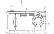
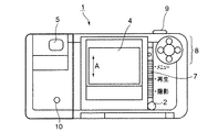
図1は、撮像装置1の正面図、図2は、撮像装置1の背面図である。
FIG. 1 is a front view of the
図1、図2に示すように、撮像装置1は、電源ボタン2と、光学系3と、LCD(Liquid Crystal Display)4と、光学ファインダー5と、内蔵フラッシュ6と、モード設定スイッチ7と、4連スイッチ8と、シャッターボタン9と、長秒モニタリングスイッチ10とを備える。
As shown in FIGS. 1 and 2, the
電源ボタン2は、撮像装置1の電源のオンオフを切り替えるものである。
The
光学系3は、ズームレンズや図略のメカニカルシャッター等を備えてなり、CCD(Charge Coupled Device)等の撮像素子11(図3参照)の撮像面に、被写体の光学像を結像するものである。
The
LCD4は、ライブビュー画像及び後述するメモリカードm(図3参照)に記録する画像(記録画像)の表示や、メモリカードmに記録された画像の再生表示等を行うものである。
The
ライブビュー画像は、被写体の画像を記録するまでの期間、一定の周期(1/30秒)でLCD4に切換表示される撮像素子11で撮像された画像をいい、このライブビュー画像により、被写体の状態が略リアルタイムでLCD4に表示され、撮影者は被写体の状態をLCD4で確認することができる。
The live view image is an image picked up by the
光学ファインダー5は、被写体が撮影される範囲を光学的に観察できるようにするものである。
The
内蔵フラッシュ6は、撮像素子11への露光量が不足している場合等に、該被写体に照明光を照射するものである。
The built-in
モード設定スイッチ7は、被写体像の撮影を行なう「撮影モード」と、メモリカードmに記録された撮影画像をLCD4に再生表示する「再生モード」と、各種機能の設定を行うための「メニューモード」との間でモードの切換設定を行うためのスイッチである。モード設定スイッチ7は、上下にスライドする3接点のスライドスイッチからなり、下にセットすると撮像装置1は撮影モードに設定され、中央にセットすると再生モードに設定され、上にセットするとメニューモードに設定される。
The
4連スイッチ8は、詳細には説明しないが、ズームレンズの光軸方向への移動や、露出補正、あるいはLCD4に再生する記録画像のコマ送り等を行うためのスイッチである。また、本実施形態の撮像装置1は、撮影モードの種類として、プログラムAEモード、絞り優先AEモード、シャッター速度優先AEモード、マニュアルモード及びバルブ撮影モードが備えられており、モード設定スイッチ7によりメニューモードが設定された状態で4連スイッチ8が操作されることにより、これらのモードを切り換えることができる。
Although not described in detail, the
プログラムAEモードは、予め設定されたAE(Auto Exposure)プログラムにしたがって絞り値とシャッタースピードとの組合せを自動的に設定するモードであり、絞り優先AEモードは、撮影者により予め設定された絞り値でシャッタースピードを設定して撮像を行うモードであり、シャッター速度優先AEモードは、撮影者により予め設定されたシャッタースピードで絞り値を設定して撮像を行うモードであり、マニュアルモードは、撮影者により予め設定されたシャッタースピードと絞り値とで撮像を行うモードである。 The program AE mode is a mode in which a combination of an aperture value and a shutter speed is automatically set according to a preset AE (Auto Exposure) program. The aperture priority AE mode is an aperture value preset by a photographer. The shutter speed setting AE mode is a mode in which an image is taken by setting an aperture value at a shutter speed preset by the photographer, and the manual mode is a mode in which the photographer takes a picture. Is a mode in which imaging is performed with a shutter speed and an aperture value set in advance.
また、バルブ撮影モードは、図略のメカニカルシャッターを開閉するタイミングを撮影者がシャッターボタン9で指示するバルブ撮影を行うモードであり、シャッターボタン9が完全に押し切られる(以下、この操作を全押し操作という)ことで電子シャッターにより記録用の露光動作が開始され、シャッターボタン9の全押しが解除されることでメカニカルシャッターが閉じてその露光動作が終了される。したがって、このバルブ撮影モードでは、撮像装置1に比較的長時間(例えば10秒など)露光させて被写体を撮影することができる。
The bulb shooting mode is a mode in which the photographer instructs the
シャッターボタン9は、2段階(半押し及び全押し)で押圧操作されるボタンであり、露出制御のタイミングを指示するためのものである。前記各撮影モードにおいて、シャッターボタン9が操作されていない状態では、1/30(秒)毎に被写体の光学像が取り込まれ、LCD4へのライブビュー画像の表示が行われる。また、撮像装置1は、前述のプログラムAEモード、絞り優先AEモード、シャッター速度優先AEモード及びマニュアルモードでは、シャッターボタン9が半押しされることで、ライブビュー画像の表示に加えてシャッタースピードや絞り値等の設定が行われる撮像待機状態に設定され、全押し操作されることで、メモリカードmに記録する被写体の光学像が決定される。なお、バルブ撮影モードにおけるシャッターボタン9の機能は前述の通りである。
The
ここで、本実施形態の撮像装置1は、前述したいずれかの撮影モードの設定時であって後述の長秒モニタリングモードに設定された場合に、記録用の画素信号を生成するための露光動作(以下、本露光動作という)の開始がシャッターボタン9により指示されるまでの期間だけでなく、本露光動作の期間中にも、被写体の状態(より正確には、メモリカードmに記録される画像の状態)をライブビュー画像としてリアルタイムでLCD4に表示するようにしているところに特徴を有している。
Here, the
本露光動作の期間(記録用の画素信号の生成期間)は、プログラムAEモード及び絞り優先AEモードでは、シャッターボタン9の全押し操作後であって、撮像装置1で算出されたシャッタースピードに相当するシャッター開放期間に相当し、シャッター速度優先AEモードでは、シャッターボタン9の全押し操作後であって、予め撮影者により設定されたシャッタースピードに相当するシャッター開放期間に相当し、マニュアルモードでは、シャッターボタン9の全押し操作後、撮影者により予め設定された時間(露光時間)が経過するまでの期間に相当し、バルブ撮影モードではシャッターボタン9の全押し状態が継続している期間に略相当する。
In the program AE mode and the aperture priority AE mode, the main exposure operation period (recording pixel signal generation period) corresponds to the shutter speed calculated by the
長秒モニタリングスイッチ10は、前述したいずれかの撮影モードの設定時において、本露光動作の期間が予め設定されたライブビュー画像の表示周期(例えば1/30秒)より著しく長いときに、その本露光動作期間にもライブビュー画像をLCD4に表示するモード(長秒モニタリングモード)に設定するためのものであり、押圧する毎に、長秒モニタリングモードの設定/非設定が交互に切り換えられる。なお、この長秒モニタリングモードは、特にバルブ撮影モードが設定されている場合に有効なものであるため、以下の説明においては、撮像装置1がバルブ撮影モードに設定されている場合について説明することとする。
The long-
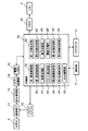
図3は、撮像装置1のシステムを示すブロック構成図である。同図において、図1,図2に示した部材と同一部材には同一の番号を付している。
FIG. 3 is a block configuration diagram showing a system of the
撮像装置1は、光学系3と、LCD4と、撮像素子11と、タイミングジェネレータ12と、信号処理部13、A/D変換部14と、画像メモリ15と、VRAM(Video Random Access Memory)16と、操作部17と、制御部18とを備えて構成されている。
The
光学系3は、図1に示す光学系3に相当するものであり、前述したようにメカニカルシャッターを備える。
The
撮像素子11は、例えばフォトダイオード等で構成される複数の光電変換素子がマトリックス状に2次元配列され、各光電変換素子の受光面に、例えばそれぞれ分光特性の異なるR(赤),G(緑),B(青)のカラーフィルタが1:2:1の比率で配設されてなるベイヤー配列のCCDカラーエリアセンサである。以下、光電変換素子にカラーフィルタが配設されたものを撮像素子11の画素という。撮像素子11は、光学系3により結像された被写体の光像をR(赤),G(緑),B(青)各色成分のアナログの電気信号(画像信号)に変換し、R,G,B各色の画像信号として出力する。
The
撮像素子11は、詳細には説明しないが、フォトダイオード等からなる受光部、垂直転送部、及び水平転送部等を備えてなるインターライン型の撮像素子であり、プログレッシブ転送方式により各画素の電荷が取り出される。すなわち、各受光部で蓄積された電荷は、垂直同期信号により垂直転送部に転送され、各垂直転送部に転送された電荷は、水平同期信号により水平転送路に近い画素から順に該水平転送路に転送されることにより画素信号として取り出される。このような撮像素子11における各画素の出力信号の読出し(水平同期、垂直同期)等の撮像動作や、撮像素子11による露光動作の開始及び終了のタイミングは、後述のタイミングジェネレータ12等により制御される。
Although not described in detail, the
本実施形態においては、撮像装置1が、長秒モニタリングスイッチ10により長秒モニタリングモードの設定時と非設定時とで、記録画像の生成方法が異なる。
In the present embodiment, the method for generating a recorded image differs between when the
すなわち、長秒モニタリングモードの非設定時には、例えばバルブ撮影モードの設定時においてシャッターボタン9の全押し操作の開始により本露光動作の開始(記録用の画素信号の生成開始)の指示が行われると、撮像素子11の略全ての画素が、シャッターボタン9の全押し操作が解除されるまでの期間、画素信号が取り出されることなく露光動作を継続して行う。そのため、LCD4には何も表示されない。その後、シャッターボタン9の全押し操作が解除されると、画素信号が取り出されることなく露光動作を継続して電荷を蓄積していたそれらの画素による本露光動作が終了しこれらの画素から画素信号が取り出され、その取り出された画素信号を用いて記録画像が生成される。
That is, when the long-second monitoring mode is not set, for example, when the bulb shooting mode is set, an instruction to start the main exposure operation (start generation of a recording pixel signal) is issued by starting full-pressing operation of the
一方、長秒モニタリングモードの設定時には、撮像素子11の複数の画素は、ライブビュー画像の表示用の画素(以下、LV表示用画素という)とメモリカードmへの記録用の画素(以下、記録用画素という)とに予め分けて利用される。
On the other hand, when the long-second monitoring mode is set, the plurality of pixels of the
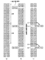
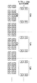
具体的には、撮像素子11の画素数とLCD4の表示画素数との比に応じて、LCD4の縦方向(図2の矢印A方向)に対応する撮像素子11における垂直方向に並ぶ複数の画素ラインのうち一部の画素ラインに位置する画素がLV表示用として用いられ、その他の画素ラインに位置する画素が記録画像用として用いられる。例えば、撮像素子11の垂直方向における画素数が2880(個)、LCD4の垂直方向における表示画素数が240(個)の場合には、図4に示すように、12列の画素ライン毎に1列の画素ラインをライブビュー画像用として用いる。なお、図4では、撮像素子11の横2列の画素ラインのみを図示したものである。
Specifically, in accordance with the ratio between the number of pixels of the
そして、シャッターボタン9の全押し操作の開始により本露光動作の開始(記録用の画素信号の生成開始)の指示が行われると、LV表示用画素及び記録用画素による露光動作が行われる。
When an instruction to start the main exposure operation (start generation of a recording pixel signal) is issued by starting full-pressing operation of the
また、本露光動作の期間、LV表示用画素から所定の時間間隔で画素信号が取り出され、その取り出された画素信号を用いて順次ライブビュー画像が生成される。これにより、LCD4に一定の時間間隔でライブビュー画像が表示される。また、これと並行して、記録用画素は、画素信号が取り出されることなく露光動作を継続して行う。その後、シャッターボタン9の全押し操作の解除により記録用画素による本露光動作が終了し該記録用画素から画素信号が取り出されると、その取り出された画素信号を用いて記録画像が生成される。この記録画像の生成方法については後述する。
Further, during the main exposure operation, pixel signals are extracted from the LV display pixels at predetermined time intervals, and live view images are sequentially generated using the extracted pixel signals. As a result, live view images are displayed on the
タイミングジェネレータ12は、制御部18から送信される基準クロックCLK0に基づいて、撮像素子11の駆動制御信号、例えば積分開始/終了(露出開始/終了)のタイミング信号、各画素の受光信号の読出制御信号(水平同期信号,垂直同期信号等)等のクロック信号を生成し、撮像素子11に出力する。
Based on the reference clock CLK0 transmitted from the
信号処理部13は、撮像素子11から出力されるアナログの画素信号に所定のアナログ信号処理を施すものである。信号処理部13は、CDS(相関二重サンプリング)回路とAGC(オートゲインコントロール)回路とを有し、CDS回路により画素信号のノイズの低減を行い、AGC回路により画素信号のレベル調整を行う。
The
A/D変換部14は、信号処理部13により出力されたアナログのR,G,Bの画素信号を、複数のビットからなるデジタルの画素信号にそれぞれ変換するものである。
The A /
画像メモリ15は、A/D変換部14から出力される画素信号を一時的に格納するとともに、この画像信号に対して制御部18により後述の処理を行うための作業領域として用いられるメモリである。
The
VRAM16は、LCD4に再生表示される画像の画素信号のバッファメモリであり、LCD4の画素数に対応した画素信号の記録容量を有する。
The
操作部17は、シャッターボタン9のレリーズ操作を検出するスイッチ、モード設定スイッチ7、4連スイッチ8及び長秒モニタリングスイッチ10等を含むものである。
The
制御部18は、例えば制御プログラムを記憶するROMや一時的にデータを記憶するRAMからなる記憶部(後述する第1、第2画像記憶部30,31を含む)が内蔵されたマイクロコンピュータからなり、上述した各部材の駆動を関連付けて制御するものである。
The
ここで、本露光動作中にもライブビュー画像をLCD4に表示する意義等について説明する。
Here, the significance and the like of displaying the live view image on the
長秒モニタリングモードの設定時において露光時間が長い(例えばバルブ撮影モードでシャッターボタン9が比較的長時間全押しされた等)ときに、シャッターボタン9の全押し操作開始以降に行われる撮像素子11の露光動作によって得られる全ての画素信号を、メモリカードmへの記録用として用いるように構成した場合、ライブビュー画像表示用として用いることのできる画素信号が無いため、シャッターボタン9の全押し中において、メモリカードmに記録される画像の状態をライブビュー画像としてLCD4に表示することはできない。
When the long-second monitoring mode is set, when the exposure time is long (for example, when the
また、本露光動作の期間に、前述のライブビュー画像をLCD4に表示する構成を備えた場合であっても、各時点における被写体の状態を示した画像をライブビュー画像として表示する構成では、次のような不具合が生じる。
Further, even when the above-described configuration for displaying the live view image on the
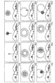
図5は、シャッターボタン9の全押し操作が開始されてから12秒間にわたって連続的に打ち上げられた3発の花火について、その12秒間の期間における各時点でLCD4に表示されるライブビュー画像を示したものであり、この図5においては、各時点で、その1/30秒前に撮像された被写体の状態がライブビュー画像として表示されている。
FIG. 5 shows a live view image displayed on the
このようなライブビュー画像の表示方法では、この12秒間のうちいずれかのタイミングで本露光動作の終了を指示しようとする場合に、その指示タイミングまでの花火の軌跡がLCD4に表示されないから、撮影者は、花火の状態を直接視認することで、例えば花火の状態が最も鮮やかになる等の所望の状態となるタイミングを予測し、その予測タイミングで撮像する被写体像を決定することとなる。
In such a live view image display method, when the end of the main exposure operation is to be instructed at any timing within the 12 seconds, the fireworks locus is not displayed on the
しかし、この場合、撮像装置1の一連の撮像動作が完了するまで、どのような画像が得られたのかが不明であり、また、メモリカードmに記録された画像が所望の画像と大きく異なる場合がある。
However, in this case, it is unclear what image was obtained until a series of imaging operations of the
以上の点に鑑みて、本実施形態では、撮像装置1に前述したような長秒モニタリングモードを備え、この長秒モニタリングモードの設定時には、シャッターボタン9の全押し操作が行われるまでの期間、すなわち本露光動作の開始が指示されるまでの期間に加えて、本露光動作の露光時間がライブビュー画像の表示周期(例えば1/30秒)より著しく大きいとき、この本露光動作の期間(全押し状態が継続している期間に略相当)にもメモリカードmに記録される画像の状態をライブビュー画像としてLCD4にリアルタイムで表示するようにしている。
In view of the above points, in the present embodiment, the
そして、このような構成を実現するため、前述したように、撮像素子11の複数の画素をLV表示用画素と記録用画素とに分け、本露光動作が終了し画素信号が取り出されるまでの期間は、LV表示用画素で生成される画素信号を一定の周期(例えば1/10秒)で読み出し、この読み出した画素信号を用いて順次ライブビュー画像を生成しLCD4に表示する。
In order to realize such a configuration, as described above, a plurality of pixels of the
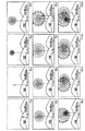
また、本実施形態では、メモリカードmに記録される画像の状態をLCD4に表示させるため、図6に示すように、長秒モニタリングモードの設定時において、記録用画素による本露光動作の期間、前回の周期で生成されたライブビュー画像(正確には後述の加算画像)と今回の周期で得られる画像とを加算することで、今回のライブビュー画像を生成することにより、各時点で撮像される画像を重畳したライブビュー画像を表示する。
Further, in the present embodiment, since the state of the image recorded on the memory card m is displayed on the
例えば、図6に示すように、シャッターボタン9の全押し操作の開始から12秒後には、その12秒間の期間に時間差をもって打ち上げられた3発の花火があたかも同時に開いたかのように画像が重畳されたライブビュー画像が生成され、そのライブビュー画像がLCD4に表示される。
For example, as shown in FIG. 6, after 12 seconds from the start of the full-pressing operation of the
そして、撮像装置1は、シャッターボタン9の全押し操作の解除により記録用画素による本露光動作の終了が指示されると、記録用画素から出力される画素信号を用いて記録画像を生成する。その際、LV表示用画素からはライブビュー画像の表示のために画素信号が取り出されており、このままでは、このLV表示用画素に対応する部分で画像が欠落するので、本実施形態の撮像装置1は、後述するように、この欠落した部分を記録用画素から得られる画素信号を用いて補間するようにしている。
Then, when the end of the main exposure operation by the recording pixel is instructed by releasing the full press operation of the
以上のような構成を実現すべく、図3に示すように、制御部18は、機能的に、第1撮像制御部19、第1記録制御部20、加算処理部21、アスペクト補正処理部22、第2撮像制御部23、第2記録制御部24、RAW補間部25、第1画像処理部26、第2画像処理部27、表示制御部28、画像圧縮部29、第1画像記憶部30及び第2画像記憶部31を備えている。
In order to realize the configuration as described above, as shown in FIG. 3, the
第1撮像制御部19は、長秒モニタリングモードの設定時において、バルブ撮影モードに設定されてからシャッターボタン9により本露光動作の終了が指示されるまでの期間において、LCD4の縦方向(図2の矢印A方向)に対応する画素の配列方向において、所定の間隔を介して並ぶ複数の画素ラインをLV表示用の画素ラインとして選定し、このLV表示用画素に露光動作を行わせつつ該LV表示用画素から所定の周期(例えば1/30秒)で画素信号を取り出す一方、記録用画素から画素信号を取り出さず露光動作を行わせるように、タイミングジェネレータ12から撮像素子11に出力されるクロック信号を制御するものである。
When the long-second monitoring mode is set, the first
例えば、図4(a)は、撮像素子11における垂直方向の複数の画素ラインのうち、12列の画素ライン毎に1列の画素ラインがLV表示用の画素ラインとして設定され、図4(b)は、他の画素ラインは記録画像用の画素ラインとして設定されたものを示したものであり、第1撮像制御部19は、シャッターボタン9により本露光動作の終了が指示されるまでの期間、LV表示用の画素ラインに位置する画素から所定の周期(例えば1/30秒)で画素信号を取り出す一方、記録画像用の画素ラインからは画素信号を取り出さないで、露光動作を継続させる。
For example, in FIG. 4A, among a plurality of vertical pixel lines in the
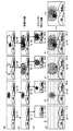
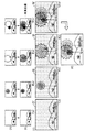
図7は、長秒モニタリングモードの設定時において、シャッターボタン9の全押し操作の開始から12秒間にわたって連続的に打ち上げられた3発の花火について、前記開始タイミングから1秒経過した時点、4秒経過した時点、8秒経過した時点及び12秒経過した時点を一例として、各時点においてLV表示用画素から得られる画像(a)と、後述する加算処理後のデータを用いて生成される画像(b)と、アスペクト補正後のデータを用いて生成される画像(c)と、記録用画素から得られるRAWデータを用いて生成される画像(d)と、メモリカードmに記録する記録画像(e)とを示したものである。
FIG. 7 shows the time when 1 second has elapsed from the start timing of 3 fireworks fired continuously for 12 seconds from the start of the full-pressing operation of the
本実施形態においては、シャッターボタン9の全押し操作の開始による本露光動作の開始後、例えば1秒経過した時点で記録用画素からRAWデータを読み出したものと仮定した場合に得られる画像は図7(d−1)に示すような画像となり、この図7(d−1)における黒線Pは、本露光動作中にライブビュー画像を表示すべくLV表示用画素の画素信号が用いられることにより欠落した部分である。
In the present embodiment, the image obtained when it is assumed that, for example, RAW data has been read from the recording pixels after one second has elapsed after the start of the main exposure operation by starting the full press operation of the
なお、第1撮像制御部19は、長秒モニタリングモードの非設定時において、シャッターボタン9により本露光動作の開始が指示されるまでの期間は、上記と同様、LV表示用画素から所定の周期(例えば1/30秒)で画素信号を取り出し、シャッターボタン9により本露光動作の開始が指示されると、撮像素子11の略全ての画素により記録用の画素信号を生成するため、どの画素からも画素信号は取り出されない。したがって、本露光動作の期間は、LCD4に何も表示されない。
Note that, when the long-second monitoring mode is not set, the first
第1記録制御部20は、長秒モニタリングモードの設定時に、本露光動作の開始から終了までの期間において、LV表示用画素からA/D変換部14等の処理を経て出力されるRAWデータ(図7(d)に示す黒線Pの部分に対応する画素信号)を、一時的に第1画像記憶部30に記録するものである。第1画像記憶部30に記録される、図7(a)に示すように、この黒線Pの部分に対応するLV表示用画素から得られるRAWデータは、図7(a)に示すように、該RAWデータから生成される画像を上下方向に隣接させた状態に対応する形で第1画像記憶部30に記録される。
When the long recording mode is set, the first
加算処理部21は、長秒モニタリングモードの設定時に、本露光動作の開始後における第2番目の周期以降、第1画像記憶部30にRAWデータが記録されるたびに、それらのRAWデータを順次加算処理し、この加算処理したデータを第1画像記憶部30に記録するものである。
When the long-second monitoring mode is set, the
図7に示すように、本露光動作の開始後、例えば1秒経過した時点では、加算処理部21は、その時点においてLV表示用画素から出力されるRAWデータからなる画像(a−1)と、その時点より1周期(例えば1/30秒)前において加算処理されたRAWデータからなる加算画像とを加算してなる加算画像(b−1)を生成する。同様に、本露光動作の開始後、例えば4秒経過した時点、8秒経過した時点、12秒経過した時点においても、加算処理部21は、各時点でLV表示用画素から出力されるRAWデータからなる画像(a−2),(a−3),(a−4)と、その時点より1周期(例えば1/30秒)前において加算処理されたRAWデータからなる加算画像とを加算してなる加算画像(b−2),(b−3),(b−4)を生成する。
As shown in FIG. 7, for example, when 1 second has elapsed after the start of the main exposure operation, the
このように、今回の周期で得られた画素信号からなる画像をPn(n=1,2,…,k−1,k)と表すものとすると、LV表示用画素による露光動作及びこの露光動作により得られるRAWデータの読み出しをn回繰り返して加算されたデータGnは、Gn=P1+P2+…+Pnとなる。 As described above, when an image composed of pixel signals obtained in the current cycle is represented as Pn (n = 1, 2,..., K−1, k), the exposure operation by the LV display pixel and the exposure operation are performed. The data Gn obtained by repeating the reading of the RAW data obtained n by n times becomes Gn = P1 + P2 +... + Pn.
アスペクト補正処理部22は、図7(c)に示すように、加算処理部21により生成された加算画像をLCD4に表示する際に、この加算処理後のデータの画素数をLCD4のアスペクトに対応するように補正し、そのアスペクト補正後のデータを第2画像記憶部31に記録するものである。これにより、長秒モニタリングモードの設定時において、本露光動作の期間(シャッターボタン9の全押し動作が行われている期間)、各時点における被写体の画像を重畳させたライブビュー画像(動体の軌跡が全て表示された画像)をLCD4に表示することができる。
When the addition image generated by the
第2撮像制御部23は、本露光動作の終了が指示されたとき、長秒モニタリングモードの設定時では、記録用画素から画素信号を出力させるべくタイミングジェネレータ12から撮像素子11に出力されるクロック信号を制御し、長秒モニタリングモードの非設定時では、略全ての画素から画素信号を出力させるべくタイミングジェネレータ12から撮像素子11に出力されるクロック信号を制御するものである。
When the end of the main exposure operation is instructed, the second
第2記録制御部24は、第2撮像制御部23による制御によりA/D変換部14等を介して得られたRAWデータを、一時的に第2画像記憶部31に記録するものである。
The second
RAW補間部25は、第2記録制御部24により第2画像記憶部31に記録されたRAWデータを用いてRAW補間処理を行うものである。すなわち、例えば、RAW補間部25は、本露光動作がその開始から12秒経過した時点で終了したものとすると、RAW補間部25は、LV表示のために欠落したRAWデータ(図7(d−4)に示す黒線部分Pの欠落した画像に対応するRAWデータ)を、その時点で記録用画素からA/D変換部14等の処理を経て得られるRAWデータを用いて補間する。このRAW補間処理の詳細な内容については後述する。
The
第1画像処理部26は、アスペクト補正処理部22から出力されるアスペクト補正画像、長秒モニタリングモードの設定時にはRAW補間部25から出力されるRAW補間後のRAWデータ、及び長秒モニタリングモードの非設定時には第2画像記憶部31に記録された略全てのRAWデータから各画素の画素データ(以下、RGB画素データという)を算出するものである。すなわち、第1画像処理部26は、各画素について、例えば当該画素が左上隅に位置するような隣接する4つの画素(Gの画素が2つ、R,Bの画素がそれぞれ1つずつ)を選定し、この4つの画素のRAWデータからRGB画像を生成する。
The first
第2画像処理部27は、第1画像処理部26による処理後のRGB画像に対し、黒レベルを基準の黒レベルに補正する黒レベル補正、光源に応じた白の基準に基づいて、R(赤)、G(緑)、B(青)の各色成分のデジタル信号のレベル変換を行うホワイトバランスの調整、R(赤),G(緑),B(青)の各色のデジタル信号のγ特性を補正するγ補正を行うものである。
The second
表示制御部28は、第2画像処理部27から出力される画像をLCD4に表示させるべく、その画像の画素データをVRAM16に転送するものである。これにより、長秒モニタリングモードの非設定時には、本露光動作が開始されるまでの期間、また、長秒モニタリングモードの設定時には、本露光動作が開始されるまでの期間に加えて本露光動作期間中にも、LCD4に被写体の状態(長秒モニタリングモードではメモリカードmに記録される画像の状態)をライブビュー画像としてリアルタイムで表示することができる。
The
画像圧縮部29は、第2画像処理部27により上記各種の処理が施された記録画像の画素データに、2次元DCT(Discrete Cosine Transform)変換、ハフマン符号化等のJPEG(Joint Picture Experts Group)方式による所定の圧縮処理を施して圧縮画像データを生成し、この圧縮画像データに、撮影画像に関する情報(圧縮率等の情報)を付加した画像ファイルをメモリカードmに記録するものである。
The
メモリカードmには、画像データが時系列的に配列して記録され、各コマ毎に、JPEG方式により圧縮された圧縮画像が、撮影画像に関するインデックス情報(コマ番号、露出値、シャッタースピード、圧縮率、撮影日、撮影時のフラッシュのオンオフのデータ、シーン情報等の情報)とともに記録される。 In the memory card m, image data is recorded in time series, and for each frame, the compressed image compressed by the JPEG method includes index information (frame number, exposure value, shutter speed, compression) about the captured image. Information such as rate, shooting date, flash on / off data at the time of shooting, and scene information).
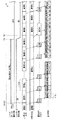
次に、本実施形態の撮像装置1の特徴部分である長秒モニタリングモードの設定時における撮像処理を、図8に示すタイムチャートを用いて説明する。
Next, imaging processing at the time of setting the long-second monitoring mode, which is a characteristic part of the
図8に示すように、長秒モニタリングモードの設定時においては、時刻T=T1でシャッターボタン9の全押し操作が行われるまで、LV表示用画素の画素信号によりライブビュー画像が生成され、表示制御部28は、このライブビュー画像をLCD4に表示させる。なお、ここでは、撮像装置1がバルブ撮影モードに設定されていることを前提としているため、メカニカルシャッターは、シャッターボタン9の全押し操作が解除されるまで開放状態が継続され、LV表示用画素及び記録用画素はその解除時点まで継続して露光動作を行う。
As shown in FIG. 8, when the long second monitoring mode is set, a live view image is generated and displayed by the pixel signal of the LV display pixel until the
そして、時刻T=T1でシャッターボタン9の全押し操作が開始されると、第1撮像制御部19は、その全押し開始タイミングより所定時間遅延した時刻T=T2から、LV表示用画素に1/10秒の周期で画素信号を出力させる一方、記録用画素からは画素信号を出力させることなく露光動作を継続して行わせる。
When the full-press operation of the
そして、第1記録制御部20は、第1画像記憶部30の記憶領域をクリアにした後、1/10秒の周期でLV表示用画素から読み出した画素信号を第1画像記憶部30に記憶させる。この取得した画素信号がシャッターボタン9の全押し開始以降の第1回目の周期で得られたものである場合には、加算処理部21による加算処理を実行せず、アスペクト補正処理部22及び第2画像処理部27は、アスペクト補正処理等の各種処理を施す。一方、前記読み出した画素信号が第2回目以降の周期で得られたものである場合には、加算処理部21は、各時点でLV表示用画素から出力され第1画像記憶部30に記録された画像と、その時点より1周期前において生成された加算画像とを加算する加算処理を行った後、アスペクト補正処理部22及び第2画像処理部27は、アスペクト補正処理等の各種処理を施す。
Then, after clearing the storage area of the first
そして、アスペクト補正処理等の処理が終了すると、表示制御部28は、この処理後の画像をLCD4に表示させ、シャッターボタン9の全押し操作が解除されるまで前述の処理が繰り返し行われる。これにより、LCD4には、各時点で撮像された画像が重畳されたライブビュー画像が表示される。
When the processing such as the aspect correction processing is completed, the
図8においては、ライブビュー画像の表示周期は、1/30秒とされているため、LV表示用画素から次の周期で画素信号を取得するまでの間(1/10秒間)、各周期で得られた画素信号により構成される画像が、それぞれ3回ずつLCD4に表示されることを示している。例えば、シャッターボタン9の全押し操作が開始されてから、第1回目の周期、すなわち「蓄積1」の期間でLV表示用画素から得られた画素信号「出力1」が、「画像1」として3回LCD4に表示される。また、第2回目以降の周期、例えば第2回目の周期である「蓄積2」の期間でLV表示用画素から得られた画素信号「出力2」が、この画素信号により構成される「画像2」と前述の「画像1」とが加算され、この加算画像「画像1+2」が3回LCD4に表示される。また、図8においては、シャッターボタン9の全押し操作中におけるLV表示用画素の画素信号の読み出し動作(垂直転送路への電荷の転送等)が50回にわたって周期的に行われたことを示す。
In FIG. 8, since the display cycle of the live view image is 1/30 second, until the pixel signal is acquired from the LV display pixel in the next cycle (1/10 second), each cycle is displayed. It shows that the image composed of the obtained pixel signals is displayed on the
そして、時刻T=T3でシャッターボタン9の全押し操作が解除されると、メカニカルシャッターが閉じられその解除タイミングより所定時間遅延した時刻T=T4で、シャッターボタン9の全押し操作の開始以降、露光動作を継続して行っていた記録用画素による露光動作が終了され、第2撮像制御部23は、時刻T=T2から時刻T=T4までの「蓄積α」の期間、画素信号が読み出されることなく継続して行われた記録用画素による露光動作によって生成された画素信号「出力α」をその記録用画素に出力させ、第2記録制御部20は、この画素信号「出力α」を第2画像記憶部31に記憶させる。
Then, when the full-pressing operation of the
その後、第2画像処理部27は、第2画像記憶部31に記憶された画素信号「出力α」に対し黒レベル補正等の処理を施した後、画像圧縮部29は、圧縮処理を施してこの圧縮後の画像をメモリカードmに記録する。なお、表示制御部28は、シャッターボタン9の全押し操作が解除される直前に生成された加算画像「1+…+49」に対してアスペクト補正処理等の各種処理を施された画像を所定時間LCD4に表示させる。
Thereafter, the second
次に、本実施形態の特徴部分である、前述のRAW補間部25によるRAW補間処理について、図4を用いて説明する。
Next, RAW interpolation processing by the above-described
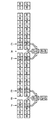
図4(a)は、撮像素子11の全ての画素からA/D変換部14等を介して出力されるRAWデータの配列を示し、同図(b)は、本露光動作の期間において、LV表示用及び記録画像用として用いられる画素を示し、同図(c)は、本露光動作の期間にライブビュー画像を表示するように構成したことにより欠落したRAWデータの補間方法を示すものである。
4A shows an array of RAW data output from all the pixels of the
図4(b)に示すように、記録画像用の画素から得られるRAWデータにより構成される画像は、LV表示用の画素ライン分だけRAWデータが垂直方向に所定間隔で欠落したものとなり、前述したように、本実施形態では、記録画像用の画素から得られるRAWデータを用いて、この欠落した画素データを補間するようにしている。 As shown in FIG. 4B, the image composed of the RAW data obtained from the pixels for the recorded image has RAW data missing from the LV display pixel lines at a predetermined interval in the vertical direction. As described above, in this embodiment, the missing pixel data is interpolated using the RAW data obtained from the pixels for the recorded image.
その際、RAWデータの状態で補間処理を行うとともに、補間後の各RAWデータの配列をベイヤー配列とすれば、補間処理を行って長秒モニタリングモードの非設定時と同じサイズの画像を得る場合に、第2画像処理部27以降の処理を長秒モニタリングモードの非設定時と共通化することができる。このことから、図4(c)に示すように、例えば矢印Aに示す画素ラインについて、左側の画素にはG(緑)の画素信号を、右側の画素にはB(青)のRAWデータを補間し、また、例えば矢印Bに示す画素ラインについて、左側の画素にはR(赤)のRAWデータを、右側の画素にはG(緑)のRAWデータを補間するのが好ましい。
At that time, when interpolation processing is performed in the state of RAW data and each RAW data array after interpolation is a Bayer array, an interpolation process is performed to obtain an image of the same size as when the long-second monitoring mode is not set In addition, the processing after the second
そこで、本実施形態では、欠落している画素のRAWデータを、当該画素の画素ラインと同種の画素ラインに位置する画素のRAWデータを用いて補間し、補間後のRAWデータの配列がベイヤー配列となるようにしている。 Therefore, in this embodiment, the RAW data of the missing pixel is interpolated using the RAW data of the pixel located on the same type of pixel line as the pixel line of the pixel, and the array of the RAW data after the interpolation is the Bayer array. It is trying to become.
また、被写体の形状が崩れるなど不自然な画像が生成されないように、補間先の画素に最も近接する同種のRAWデータを用いて補間するようにしている。 In addition, interpolation is performed using the same type of RAW data closest to the interpolation destination pixel so that an unnatural image such as the shape of the subject is not generated is generated.
具体的に、本実施形態では、矢印Aに示す画素ラインについて、左側の画素には、矢印Cに示すように、欠落している画素の配列と同じであって、欠落している画素ラインに最も近い画素ライン(図4では2列上側に位置する画素ライン)における左側のG(緑)の画素のRAWデータを補間し、右側の画素には、矢印Cに示すように、その画素ライン(2列上側に位置する画素ライン)における右側のB(青)の画素のRAWデータを補間する。また、矢印Bに示す画素ラインについて、左側の画素には、矢印Dに示すように、欠落している画素の配列と同じであって、欠落している画素ラインに最も近い画素ライン(2列上側に位置する画素ライン)における左側のR(赤)の画素のRAWデータを補間し、右側の画素には、その画素ライン(2列上側に位置する画素ライン)における右側のG(緑)の画素のRAWデータを補間するようにしている。 Specifically, in the present embodiment, with respect to the pixel line indicated by the arrow A, the left pixel has the same arrangement of the missing pixels as indicated by the arrow C, and the missing pixel line RAW data of the left G (green) pixel in the nearest pixel line (pixel line located at the upper side of the second column in FIG. 4) is interpolated, and the pixel line ( The RAW data of the right B (blue) pixel in the pixel line located at the upper side of the second column) is interpolated. As for the pixel line indicated by the arrow B, the pixel on the left side has the same pixel array as the missing pixel line as indicated by the arrow D and is closest to the missing pixel line (two columns). RAW data of the left R (red) pixel in the upper pixel line) is interpolated and the right pixel of the right G (green) in the pixel line (pixel line located two columns above) is interpolated. The raw data of the pixel is interpolated.
これにより、第2画像処理部27以降の処理を長秒モニタリングモードの非設定時と共通化することができるとともに、被写体の画像に歪みや偽色等の発生を防止または抑制することができる。
As a result, the processing after the second
また、シャッターボタン9により本露光動作の開始が指示されるまでの期間においては、LV表示用の画素から得られるRAWデータを用いてライブビュー画像を生成するようにしたので、長秒モニタリングモードの設定時において本露光動作の期間、ライブビュー画像を確実にリアルタイムでLCD4に表示することができる。
In addition, in the period until the start of the main exposure operation is instructed by the
そして、ライブビュー画像を構成する各RAWデータの配列及び補間後のRAWデータの配列がベイヤー配列となるようにそれぞれRAWデータを選定し、第2画像処理部27による画像処理等の処理が施される前のRAWデータの状態で前述の補間処理を行うようにしたから、第2画像処理部27以降の処理を長秒モニタリングモードの非設定時と共通化することができ、第2画像処理部27による画像処理が施された後の画素データを用いて欠落部位への画素データの補間を行う構成に比して補間処理が複雑しない。
Then, the RAW data is selected so that the array of each RAW data composing the live view image and the array of the RAW data after interpolation become a Bayer array, and processing such as image processing by the second
なお、本発明は、上記実施形態に限らず、次の実施形態(1)〜(11)も採用可能である。 The present invention is not limited to the above embodiment, and the following embodiments (1) to (11) can also be employed.
(1)上記実施形態においては、欠落している画素のRAWデータを、当該画素の2列上側に位置する画素ラインの画素のRAWデータを用いて補間するようにしたが、これに限らず、処理対象の画素ラインの2列下側に位置する画素ラインの画素のRAWデータを用いて補間するようにしてもよいし、あるいは次のように補間処理を行うようにしてもよい。 (1) In the above embodiment, the RAW data of the missing pixel is interpolated using the RAW data of the pixel of the pixel line located above the second column of the pixel. You may make it interpolate using the raw data of the pixel of the pixel line located 2 columns below a pixel line to be processed, or you may perform an interpolation process as follows.
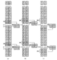
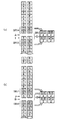
図9〜図11は、欠落している画像の補間処理方法の変形例を説明するための図である。 9 to 11 are diagrams for explaining modifications of the missing image interpolation processing method.
図9に示すように、上記実施形態(図4)と同様に画素が欠落したものとすると、矢印Aに示す画素ラインについて、左側の画素には、矢印C,Eに示すように、2列上側及び2列下側に位置する各画素ラインのうち、左側に位置するG(緑)の各画素のRAWデータの平均値を算出して、この平均値を当該画素のRAWデータとして補間し、右側の画素には、矢印C,Eに示すように、2列上側及び2列下側に位置する各画素ラインのうち、右側に位置するB(青)の各画素のRAWデータの平均値を算出して、この平均値を当該画素のRAWデータとして補間する。 As shown in FIG. 9, assuming that pixels are missing as in the above embodiment (FIG. 4), for the pixel line indicated by arrow A, the left pixel includes two columns as indicated by arrows C and E. Of the pixel lines located on the upper side and the lower side of the second column, the average value of the RAW data of each G (green) pixel located on the left side is calculated, and this average value is interpolated as the RAW data of the pixel, In the right pixel, as shown by arrows C and E, the average value of the RAW data of each B (blue) pixel located on the right side among the pixel lines located on the upper side and the lower side of the second column is shown. The average value is calculated and interpolated as RAW data of the pixel.
また、矢印Bに示す画素ラインについて、左側の画素には、矢印D,Fに示すように、2列上側及び2列下側に位置する各画素ラインのうち、左側に位置するR(赤)の各画素のRAWデータの平均値を算出して、この平均値を当該画素のRAWデータとして補間し、右側の画素には、矢印D,Fに示すように、2列上側及び2列下側に位置する各画素ラインのうち、右側に位置するG(緑)の各画素のRAWデータの平均値を算出して、この平均値を当該画素のRAWデータとして補間する。 As for the pixel line indicated by the arrow B, the left pixel includes R (red) positioned on the left side of the pixel lines positioned on the upper side and the lower side of the second column as indicated by arrows D and F. The average value of the RAW data of each pixel is calculated, and this average value is interpolated as the RAW data of the pixel. As shown by arrows D and F, the right side pixel has two columns above and two columns below. The average value of the RAW data of each G (green) pixel located on the right side among the pixel lines located at is calculated, and this average value is interpolated as the RAW data of the pixel.
これによっても、第2画像処理部27以降の処理を長秒モニタリングモードの非設定時と共通化することができるとともに、上記実施形態よりさらに被写体の画像に歪みや偽色等の発生を防止または抑制することができる。
This also makes it possible to share the processing after the second
図10(a)においては、斜線で示すように、隣接する4つの画素を1つのブロックとし、ブロック単位で処理を行うものである。 In FIG. 10A, as shown by the oblique lines, four adjacent pixels are made one block, and processing is performed in units of blocks.
図10(a)に示すように、欠落している画素ライン(矢印A,Bで示す画素ライン)の画素を含むブロックBR1,BR2に属する画素のRAWデータを、該ブロックBR1,BR2に隣接するブロックBR3,BR4の画素のRAWデータを用いて設定する。 As shown in FIG. 10A, the RAW data of the pixels belonging to the blocks BR1 and BR2 including the pixels of the missing pixel lines (pixel lines indicated by arrows A and B) are adjacent to the blocks BR1 and BR2. Setting is performed using the RAW data of the pixels of the blocks BR3 and BR4.
具体的には、矢印Aに示す画素ラインについて、左側の画素には、ブロックBR1と上側で隣接するブロックBR3の左上部に位置するG(緑)のRAWデータを、右側の画素には、ブロックBR3の右上部に位置するB(青)のRAWデータを補間する。また、矢印Gに示す画素ラインについて、左側のR(赤)の画素のRAWデータを、ブロックBR3の左下部に位置するR(赤)のRAWデータに置換し、右側のG(緑)の画素のRAWデータを、ブロックBR3の右下部に位置するG(緑)のRAWデータに置換する。 Specifically, for the pixel line indicated by the arrow A, G (green) RAW data located in the upper left part of the block BR3 adjacent to the upper side of the block BR1 is displayed on the left pixel, and Interpolates B (blue) RAW data located in the upper right part of BR3. For the pixel line indicated by the arrow G, the RAW data of the left R (red) pixel is replaced with the R (red) RAW data located at the lower left of the block BR3, and the right G (green) pixel. Is replaced with G (green) RAW data located in the lower right part of the block BR3.
同様に、矢印Bに示す画素ラインについて、左側の画素には、ブロックBR2と上側で隣接するブロックBR4の左上部に位置するR(赤)のRAWデータを、右側の画素には、ブロックBR4の右上部に位置するG(緑)のRAWデータを補間する。また、矢印Hに示す画素ラインについて、左側のG(緑)の画素のRAWデータを、ブロックBR4の左下部に位置するG(緑)のRAWデータに置換し、右側のB(青)の画素のRAWデータを、ブロックBR4の右下部に位置するB(青)のRAWデータに置換する。 Similarly, with respect to the pixel line indicated by arrow B, the left pixel has R (red) RAW data located in the upper left portion of the block BR4 adjacent to the upper side of the block BR2, and the right pixel has the block BR4. G (green) RAW data located in the upper right part is interpolated. For the pixel line indicated by the arrow H, the RAW data of the left G (green) pixel is replaced with the G (green) RAW data located in the lower left part of the block BR4, and the right B (blue) pixel. Are replaced with B (blue) RAW data located in the lower right part of the block BR4.
このように、欠落した画素に、近傍に位置する同色の画素のRAWデータを補間または置換するだけでよいから、比較的簡単な処理で自然な記録画像を得ることができる。また、この場合は、ブロック単位で補間するため、画素ライン単位で補間する場合に比して、直線等の画像の再現において優れている。 As described above, since it is only necessary to interpolate or replace the RAW data of the same color pixel located in the vicinity of the missing pixel, a natural recorded image can be obtained by relatively simple processing. In this case, since the interpolation is performed in units of blocks, it is superior in reproducing an image such as a straight line as compared with the case of performing interpolation in units of pixel lines.
なお、図10(a)においては、処理対象の画素ラインとその下の画素ラインとでブロックを構成し、このブロックに属する画素のRAWデータを、該ブロックの上側に隣接するブロックに属する画素のRAWデータで補間または置換するようにしたが、これに限られない。 In FIG. 10A, a pixel line to be processed and a pixel line below it constitute a block, and the RAW data of the pixels belonging to this block are converted to the pixels belonging to the block adjacent to the upper side of the block. Although interpolation or replacement is performed with RAW data, the present invention is not limited to this.
例えば、図10(b)に示すように、処理対象の画素ラインとその上の画素ラインとでブロックBR5,BR7を構成し、このブロックBR5,BR7に属する画素のRAWデータを、該ブロックBR5,BR7の上側に隣接するブロックBR6,BR8に属する画素のRAWデータで補間または置換してもよい。あるいは、図10(c)に示すように、処理対象の画素ラインとその下の画素ラインとでブロックBR9,BR11を構成し、このブロックBR7,BR11に属する画素のRAWデータを、該ブロックBR7,BR11の下側に隣接するブロックBR10,BR12に属する画素のRAWデータで補間または置換するようにしてもよい。 For example, as shown in FIG. 10 (b), the processing target pixel line and the pixel line above it constitute blocks BR5 and BR7, and the RAW data of the pixels belonging to the blocks BR5 and BR7 are converted into the block BR5. Interpolation or replacement may be performed with RAW data of pixels belonging to the blocks BR6 and BR8 adjacent to the upper side of BR7. Alternatively, as shown in FIG. 10 (c), the processing target pixel line and the pixel line below it constitute blocks BR9 and BR11, and the RAW data of the pixels belonging to the blocks BR7 and BR11 are transferred to the block BR7, You may make it interpolate or substitute by the raw data of the pixel which belongs to the blocks BR10 and BR12 which adjoin below BR11.
図11においては、斜線で示すように、隣接する4つの画素を1つのブロックとし、ブロック単位で処理を行う点は図10と同様であるが、処理対象の画素ラインとその上の画素ライン又はその下の画素ラインとでブロックを構成し、このブロックに属する画素のRAWデータを、該ブロックの両側に隣接するブロックに属する画素の平均のRAWデータで補間または置換するものである。 In FIG. 11, as shown by hatching, four adjacent pixels are made one block, and the processing is performed in units of blocks, as in FIG. 10, but the pixel line to be processed and the pixel line above it or A block is composed of the lower pixel lines, and RAW data of pixels belonging to this block is interpolated or replaced with average RAW data of pixels belonging to blocks adjacent to both sides of the block.
図11(a)に示すように、矢印Aについては、その下側の矢印Iで示す画素ラインとで1つのブロックBR13を構成している。そして、矢印Aに示す画素ラインについて、左側の画素には、ブロックBR13と上側及び下側で隣接するブロックBR14及びBR15のそれぞれ左上部に位置する各G(緑)の画素の平均のRAWデータを補間し、右側の画素には、ブロックBR14及びBR15のそれぞれ右上部に位置する各B(青)の画素の平均のRAWデータを補間する。 As shown in FIG. 11A, for the arrow A, the pixel line indicated by the arrow I below forms one block BR13. With respect to the pixel line indicated by the arrow A, the average RAW data of each G (green) pixel located in the upper left part of each of the blocks BR14 and BR15 adjacent to the block BR13 on the upper and lower sides in the pixel on the left side. Interpolation is performed, and average RAW data of each B (blue) pixel located in the upper right part of each of the blocks BR14 and BR15 is interpolated to the right pixel.
また、矢印Iに示す画素ラインについて、左側のR(赤)の画素のRAWデータを、ブロックBR14及びBR15のそれぞれ左下部に位置するR(赤)のRAWデータに置換し、右側のG(緑)の画素のRAWデータを、ブロックBR14及びBR15のそれぞれ右下部に位置するG(緑)のRAWデータに置換する。 For the pixel line indicated by the arrow I, the RAW data of the left R (red) pixel is replaced with the R (red) RAW data located at the lower left of each of the blocks BR14 and BR15, and the right G (green) ) Pixel data is replaced with G (green) RAW data located in the lower right part of each of the blocks BR14 and BR15.
また、図11(b)に示すように、矢印Bについては、その上側の矢印Jで示す画素ラインとで1つのブロックBR16を構成している。そして、矢印Bに示す画素ラインについて、左側の画素には、ブロックBR16と上側及び下側で隣接するブロックBR17及びBR18のそれぞれ左上部に位置する各G(緑)の画素の平均のRAWデータを補間し、右側の画素には、ブロックBR17及びBR18のそれぞれ右上部に位置する各B(青)の画素の平均のRAWデータを補間する。 In addition, as shown in FIG. 11B, for the arrow B, one pixel BR16 is constituted by the pixel line indicated by the arrow J above the arrow B. With respect to the pixel line indicated by the arrow B, the average RAW data of each G (green) pixel located in the upper left of each of the blocks BR17 and BR18 adjacent to the block BR16 on the upper side and the lower side in the pixel on the left side. Interpolation is performed, and average RAW data of each B (blue) pixel located in the upper right part of each of the blocks BR17 and BR18 is interpolated to the right pixel.
また、矢印Jに示す画素ラインについて、左側のG(緑)の画素のRAWデータを、ブロックBR17及びBR18のそれぞれ左下部に位置するG(緑)のRAWデータに置換し、右側のB(青)の画素のRAWデータを、ブロックBR17及びBR18のそれぞれ右下部に位置するB(青)のRAWデータに置換する。 For the pixel line indicated by arrow J, the RAW data of the left G (green) pixel is replaced with the G (green) RAW data located at the lower left of each of the blocks BR17 and BR18, and the right B (blue) ) Pixel data is replaced with B (blue) RAW data located at the lower right of each of the blocks BR17 and BR18.
この場合においても、欠落した画素に、近傍に位置する同色の画素の平均のRAWデータを補間または置換するだけでよいから、比較的簡単な処理で自然な記録画像を得ることができる。 Even in this case, it is only necessary to interpolate or replace the average RAW data of the pixels of the same color located in the vicinity of the missing pixels, so that a natural recorded image can be obtained by a relatively simple process.
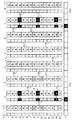
(2)上記実施形態では、ライブビュー画像を生成するに際し、列単位でLV表示用画素を選定するようにしたが、これに限らず、図12に示すように、垂直方向及び水平方向に所定の間隔を介して離間した画素(白黒反転表示した画素)を選定してもよい。 (2) In the above embodiment, when generating a live view image, LV display pixels are selected in units of columns. However, the present invention is not limited to this, and as shown in FIG. Pixels separated by the interval (pixels displayed in black and white inversion) may be selected.
その際、LV表示用の画素として選定される画素の配列がベイヤー配列となるように、垂直方向及び水平方向に(2n+1)(nは1以上の整数)ごとに、LV表示用の画素を選定すればよい。 At that time, LV display pixels are selected for each (2n + 1) (n is an integer of 1 or more) in the vertical direction and the horizontal direction so that the array of pixels selected as LV display pixels is a Bayer array. do it.
例えば、図12においては、n=2として垂直方向及び水平方向に5列ごとにLV表示用画素を選定している(LV表示用画素を黒塗りで示している)。つまり、図12において、上から垂直方向下側及び左から水平方向右側にそれぞれ番号を付したとき、垂直方向に上から4列目、9列目及び14列目で、且つ水平方向に左から2列目及び7列目に位置する画素のRAWデータを用いてライブビュー画像を生成している。 For example, in FIG. 12, n = 2 and LV display pixels are selected every five columns in the vertical and horizontal directions (LV display pixels are shown in black). That is, in FIG. 12, when numbers are assigned from the top to the bottom in the vertical direction and from the left to the right in the horizontal direction, respectively, the fourth, ninth and fourteenth rows from the top in the vertical direction and from the left in the horizontal direction. A live view image is generated using RAW data of pixels located in the second and seventh columns.
図13は、このように構成した場合であって長秒モニタリングモードの設定時に、シャッターボタンの全押し操作が開始されてから12秒間にわたって連続的に打ち上げられた3発の花火について、1秒経過した時点、4秒経過した時点、8秒経過した時点及び12秒経過した時点を一例として、各時点において、LV表示用画素のRAWデータを用いて生成される画像(a)と、加算処理後のRAWデータを用いて生成される画像(b)と、記録用画素のRAWデータを用いて生成される画像(c)と、メモリカードmに記録する記録画像(d)を示した図である。 FIG. 13 shows a case in which 1 second has elapsed with respect to the three fireworks fired continuously for 12 seconds after the shutter button full-press operation is started when the long-second monitoring mode is set. As an example, a time point of 4 seconds, a time point of 8 seconds, a time point of 12 seconds, and an image (a) generated using RAW data of LV display pixels at each time point, and after the addition process FIG. 6 is a diagram showing an image (b) generated using RAW data of the image, an image (c) generated using RAW data of a recording pixel, and a recorded image (d) recorded on the memory card m. .
図13(b)に示すように、シャッターボタン9の全押し操作後、仮に例えば1秒経過した時点において記録画像用の画素から読み出したRAWデータから得られる画像は、図13(c)に示すような画像となり、LV表示用の画素から出力されるRAWデータは、この図13(c)において黒点P’の部分に対応するものとなり、仮にこのRAWデータにより画像を生成すると、図13(a)に示すものとなる。
As shown in FIG. 13B, an image obtained from the RAW data read from the recording image pixels after, for example, 1 second has elapsed after the
そして、このようにLV表示用の画素を選定した場合に、本露光動作が終了すると、最近接の同色画素のRAWデータを用いて補間すればよい。図12において、例えば矢印Pに示すG(緑)の画素については、斜線で示す周囲に位置する4つのG(緑)の画素から得られるRAWデータの平均値を、その画素のRAWデータとすればよい。 Then, when pixels for LV display are selected in this way, when the main exposure operation is completed, interpolation may be performed using the RAW data of the closest pixel of the same color. In FIG. 12, for example, for the G (green) pixel indicated by the arrow P, the average value of the RAW data obtained from the four G (green) pixels located around the shaded area is used as the RAW data for that pixel. That's fine.
なお、図12では、垂直方向及び水平方向の両方向について5列ごとにライブビュー画像用の画素を選定するものを示したが、これに限られず、7列ごとや11列ごとにLV表示用画素を選定してもよく、また、例えば垂直方向には5列ごとに、水平方向には7列ごとにLV表示用画素を選定するというように、各方向でライブビュー画像表示用の画素として選定する画素ラインの間隔が異なってもよい。 FIG. 12 shows the case where the pixels for the live view image are selected for every five columns in both the vertical direction and the horizontal direction. However, the present invention is not limited to this, and the LV display pixels are set every seven columns or every eleven columns. In addition, for example, LV display pixels are selected every 5 columns in the vertical direction and every 7 columns in the horizontal direction, and are selected as the pixels for live view image display in each direction. The intervals of the pixel lines to be performed may be different.
(3)上記実施形態では、被写体の画像を表示するものとしてLCD4を備え、LCD4にライブビュー画像等を表示するようにしたが、これに限らず、光学ファインダー5の代わりに電子ビューファインダーが備えられている場合には、電子ビューファインダーにもライブビュー画像を表示するようにしてもよい。
(3) In the above embodiment, the
(4)上記実施形態では、12列毎に1つの画素ラインに位置する画素をライブビュー画像用として用いるようにしたが、この割合に限らず、垂直方向における、撮像素子11の画素数とLCD4の表示画素数との比に応じて、例えば6列毎に1つの割合で、あるいは16列に1つの割合等に設定することができる。
(4) In the above embodiment, the pixels located in one pixel line for every 12 columns are used for the live view image. However, the number of pixels of the
(5)上記実施形態では、LV表示用画素の配列がベイヤー配列となるように、図4(b)に示すように、垂直方向に交互に異種の画素ラインをLV表示用して選定したが、特に高画素化された撮像素子を用いた場合には、図14に示すように、各周期において、垂直方向に同種の画素ラインが所定数連続するようにライブビュー画像の画素ラインを選定し、これらの画素ラインに位置する画素からRAWデータを読み出し、この連続する同色画素のRAWデータを加算して1のRAWデータとしてライブビュー画像や記録画像を生成するようにすると、画素の縮小化による露光量の不足を補うことができる。 (5) In the above embodiment, different pixel lines are selected for LV display alternately in the vertical direction, as shown in FIG. 4B, so that the array of LV display pixels is a Bayer array. In particular, when an imaging device with a high pixel count is used, as shown in FIG. 14, the pixel lines of the live view image are selected so that a predetermined number of the same type of pixel lines continue in the vertical direction in each cycle. When the raw data is read from the pixels located in these pixel lines and the raw data of the same color pixels are added to generate a live view image or a recorded image as one raw data, Insufficient exposure can be compensated.
(6)上記実施形態においては、撮像装置1がバルブ撮影モードの設定時であって長秒モニタリングモードに設定されたときの利点について説明したが、マニュアルモードを始めとする他の撮影モードの設定時であって長秒モニタリングモードに設定された場合においても、前述のように撮像素子11の複数の画素をLV表示用と記録用とに分け、本露光動作中には、LV表示用の画素から画素信号を読み出してライブビュー画像を表示するとともに、本露光動作が終了すると記録用画素から画素信号を得て記録画像を生成するようにしてもよい。
(6) In the above embodiment, the advantage when the
(7)上記実施形態では、撮像素子を駆動するための駆動制御信号の生成の容易さの点から、プログレッシブ転送方式の撮像素子を採用したが、インターレース転送方式の撮像素子を採用した撮像装置にも本発明を適用可能である。 (7) In the above embodiment, the progressive transfer type image sensor is adopted from the viewpoint of easy generation of the drive control signal for driving the image sensor, but the image pickup apparatus adopts the interlace transfer type image sensor. The present invention is also applicable.
(8)上記実施形態では、画像を記録する手段として、メモリカードmを採用したが、これに限られず、当該撮像装置1が、例えばコンピュータなど記憶容量を有する機器と、通信ケーブル、あるいは通信ネットワークを介して通信可能に構成されている場合には、そのコンピュータ等の機器に画像を記録するようにしてもよい。
(8) In the above embodiment, the memory card m is used as a means for recording an image. However, the present invention is not limited to this, and the
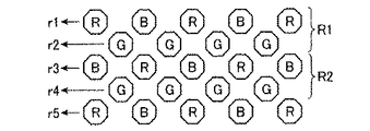
(9)本発明は、図15に示すように、八角形状の画素が市松格子状に配設された所謂ハニカムCCDにも採用可能である。 (9) The present invention can be applied to a so-called honeycomb CCD in which octagonal pixels are arranged in a checkered pattern as shown in FIG.
すなわち、図15に示すように、隣接するRGBの画素の列を1の画素ライン(例えばR1,R2)とみなした上で、上記実施形態と同様に、LV表示用として使用する画素ラインを選定するようにしてもよい。あるいは、R,Bの画素の列を1の画素ライン、Gの画素の列を1の画素ラインとみなし、上記実施形態と同様に、LV表示用として使用する画素ラインを選定するようにしてもよい。この場合、画像の歪みや偽色の少ない綺麗なライブビュー画像を得るため、LV表示用として取り出した画素信号の配列について、R,Bの画素ラインとGの画素ラインとから垂直方向(図21の縦方向)に交互に画素信号を取り出すようにするのが好ましい。 That is, as shown in FIG. 15, after considering a row of adjacent RGB pixels as one pixel line (for example, R1, R2), a pixel line used for LV display is selected as in the above embodiment. You may make it do. Alternatively, the column of R and B pixels is regarded as one pixel line, and the column of G pixels is regarded as one pixel line, and a pixel line used for LV display is selected as in the above embodiment. Good. In this case, in order to obtain a beautiful live view image with less image distortion and false color, the arrangement of pixel signals taken out for LV display is perpendicular to the R and B pixel lines and the G pixel lines (FIG. 21). It is preferable to extract pixel signals alternately in the vertical direction).
(10)前記実施形態においては、撮像素子11として、各光電変換素子の受光面に原色フィルター(R(赤),G(緑),B(青)のカラーフィルタ)を配設したCCDを採用したが、これに限られず、補色フィルター(C(シアン)、M(マゼンタ)、Y(イエロー))を配設したCCDを採用してもよい。
(10) In the above-described embodiment, a CCD in which primary color filters (R (red), G (green), and B (blue) color filters) are disposed on the light receiving surface of each photoelectric conversion element is employed as the
(11)前記実施形態のように、撮像素子11の複数の画素を前述のようにLV表示用の画素と記録用の画素とに分けて使用する技術を利用して、各撮影モードの設定時においてさらに次のようなレリーズタイムラグ短縮モードを備えることができる。
(11) At the time of setting each shooting mode, using the technique in which a plurality of pixels of the
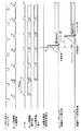
図16(a)〜(g)は、レリーズタイムラグ短縮モードの設定時における撮像素子11の各動作を示すタイミングチャートであり、図16(a)は、撮像素子11による転送路(垂直転送路及び水平転送路)のクリーニング動作を示し、図16(b)は、LV表示用画素による露光動作を示し、図16(c)は、撮像素子11に印加される垂直同期信号(VD)の出力動作を示し、図16(d)は、LV表示用画素の露光動作により生成される画素信号の読み出し動作を示し、図16(e)は、ライブビュー画像の表示動作を示し、図16(f)は、撮影者による本露光動作の終了指示操作を示し、図16(g)は、その指示操作により行われるレリーズタイムラグ短縮モードの記録動作を示す。また、図16(h)は、レリーズタイムラグ短縮モードの非設定時における記録動作とそのモードの設定時における記録動作との相違点を説明すべく、レリーズタイムラグ短縮モードの非設定時における記録動作を示すタイムチャートである。
FIGS. 16A to 16G are timing charts showing the operations of the
図16に示すように、レリーズタイムラグ短縮モードの設定時において、シャッターボタン9により本露光動作の開始指示が行われるまでの期間、前述の転送路に残留している電荷が図略のオーバーフロードレインに掃き捨てるクリーニング動作が例えば1/30秒の周期で行われ、各クリーニング動作が終了するごとに、LV表示用画素及び記録用画素による露光動作が行われる。そして、撮像素子11に垂直同期信号が印加されると、LV表示用画素による露光動作によって生成された画素信号の読み出しが行われる。読み出された画素信号から生成される画像の表示は、次の周期における画素信号の読み出し動作とほぼ並行して行われる。なお、本露光動作の開始指示が行われるまでの期間、記録用画素から読み出された画素信号については破棄される。
As shown in FIG. 16, when the release time lag shortening mode is set, the charge remaining in the transfer path is transferred to the overflow drain (not shown) until the
そして、LV表示用画素及び記録用画素からの画素信号の読み出し中にシャッターボタン9による本露光動作の開始指示が行われると、記録用画素による露光動作を継続して行い、撮像装置1は、所定の露光条件が満たされた時点でシャッターを閉じることにより、記録用画素による露光動作を終了する。
Then, when an instruction to start the main exposure operation by the
一方、レリーズタイムラグ短縮モードの非設定時においては、LV表示用画素及び記録用画素からの画素信号の読み出し中にシャッターボタン9による本露光動作の開始指示が行われると、撮像装置1は、転送路のクリーニング(その読み出していた画素信号の除去)を行った後、略全ての画素による露光動作を開始し、例えばシャッターボタン9の半押し中に算出されたシャッタースピードでメカニカルシャッターを閉じることで、その露光動作を終了する。
On the other hand, when the release time lag reduction mode is not set, if an instruction to start the main exposure operation is issued by the
このように、レリーズタイムラグ短縮モードの設定時においては、レリーズタイムラグ短縮モードの非設定時のように全ての画素を用いて記録画像を生成するのではなく、撮像素子11の一部の画素(記録用画素)を用いて記録画像を生成するから、その記録画像のサイズは、レリーズタイムラグ短縮モードの非設定時に得られる記録画像に比して小さくなる(上下方向(縦方向)に約半分)。 As described above, when the release time lag reduction mode is set, a recorded image is not generated using all the pixels as in the case where the release time lag reduction mode is not set, but some pixels (recording) are recorded. Therefore, the size of the recording image is smaller than that of the recording image obtained when the release time lag reduction mode is not set (about half in the vertical direction (vertical direction)).
しかし、本露光動作の開始指示が行われた時点で記録用画素で蓄積されている電荷を、本露光動作により生成される画素信号の一部とすることができる。換言すれば、本露光動作が、本露光動作の開始指示が行われるタイミングよりも以前からすでに行われているとみなすことができる。これにより、レリーズタイムラグ短縮モードの非設定時に比して、本露光動作の開始指示が行われたタイミングにより近いタイミングでメカニカルシャッターを閉じる(本露光動作を終了する)ことができる(T2<T1)。これにより、撮影者が望む被写体像に近い画像を記録画像として生成することができる。 However, the charge accumulated in the recording pixels at the time when the start instruction of the main exposure operation is issued can be part of the pixel signal generated by the main exposure operation. In other words, it can be considered that the main exposure operation has already been performed before the timing at which the start instruction of the main exposure operation is performed. As a result, the mechanical shutter can be closed (the main exposure operation is terminated) at a timing closer to the timing at which the start instruction of the main exposure operation is performed compared to when the release time lag reduction mode is not set (T2 <T1). . Thereby, an image close to the subject image desired by the photographer can be generated as a recorded image.
以上、説明した撮像装置1は、以下の付記1〜9に示す発明を主に含む。
The
[付記1] それぞれ異なる色を受光する複数種類の画素を備え、各画素を一方向に配列してなる画素ラインが前記一方向と交差する交差方向に複数配置してなる撮像素子と、所定の記録部に記録する記録用画素信号を生成するための露光動作の開始を前記撮像素子に指示するための入力操作部と、前記入力操作部により前記露光開始指示が行われると、前記撮像素子に露光動作を行わせるとともに、前記交差方向に並んで構成される複数の画素ラインのうち、一部の画素ラインに位置する複数の画素から所定の時間間隔でRAWデータを出力させる撮像制御部と、前記露光開始指示後の所定のタイミングで、前記複数の画素以外の他の画素からRAWデータを取得し、前記他の画素のRAWデータに基づき前記複数の画素に対応するRAWデータを補間する画像処理部と、前記画像処理部により生成された前記補間後のRAWデータからRGB画像を生成する第1画像生成部と、前記第1画像生成部により生成されたRGB画像を前記所定の記録部に記録させる記録制御部とを備えることを特徴とする撮像装置。 [Supplementary Note 1] An image pickup device including a plurality of types of pixels that receive different colors, and a plurality of pixel lines in which pixels are arranged in one direction are arranged in a crossing direction that intersects the one direction; An input operation unit for instructing the imaging device to start an exposure operation for generating a recording pixel signal to be recorded in the recording unit, and when the exposure start instruction is given by the input operation unit, the imaging device An imaging control unit that performs an exposure operation and outputs RAW data at a predetermined time interval from a plurality of pixels located in a part of the plurality of pixel lines arranged in the crossing direction; RAW data is acquired from other pixels other than the plurality of pixels at a predetermined timing after the exposure start instruction, and the RAW corresponding to the plurality of pixels is based on the RAW data of the other pixels. An image processing unit for interpolating data, a first image generation unit for generating an RGB image from the interpolated RAW data generated by the image processing unit, and an RGB image generated by the first image generation unit An imaging apparatus comprising: a recording control unit that causes the predetermined recording unit to perform recording.
[付記2] 前記画像処理部は、前記複数の画素に対応するRAWデータとして、前記複数の画素の近傍に位置する画素のRAWデータを用いて前記補間を行うことを特徴とする付記1に記載の撮像装置。
[Supplementary note 2] The
[付記3] 前記撮像素子は、前記複数種類の画素がベイヤー配列してなるものであり、前記画像処理部は、一頂点で互いに接する4つの画素をブロックとし、前記複数の画素を含むブロックに属する各画素に対し、該ブロックに隣接するブロックに属する画素のRAWデータを用いて代替のRAWデータを補間または置換することを特徴とする付記2に記載の撮像装置。
[Supplementary Note 3] The imaging element is formed by Bayer arrangement of the plurality of types of pixels, and the image processing unit uses four pixels that are in contact with each other at one vertex as a block and includes the plurality of pixels. The imaging apparatus according to
[付記4] 前記複数の画素から得られるRAWデータを所定の画素データに変換し、この画素データに基づくRGB画像を生成する第2画像生成部と、前記第2画像生成部により生成されたRGB画像を表示する画像表示部とを備えることを特徴とする付記1ないし3のいずれかに記載の撮像装置。
[Supplementary Note 4] A RAW data obtained from the plurality of pixels is converted into predetermined pixel data, and an RGB image based on the pixel data is generated, and an RGB generated by the second image generation unit The imaging apparatus according to any one of
[付記5] 前記撮像素子は、前記複数種類の画素がベイヤー配列してなるものであり、前記第2画像生成部は、前記撮像素子に備えられる画素の直交する2の配列方向にそれぞれ(2n+1)列ごとに設定された所定の画素ラインの交点上に位置する画素から得られるRAWデータに基づいて前記RGB画像を生成することを特徴とする付記4に記載の撮像装置。(nは1以上の整数)
[Supplementary Note 5] The image pickup element is formed by Bayer arrangement of the plurality of types of pixels, and the second image generation unit (2n + 1) in each of two orthogonal arrangement directions of the pixels included in the image pickup element. The imaging apparatus according to
[付記6] 前記入力操作部は、さらに、前記所定の記録部に記録する画像を得るための前記撮像素子による露光動作の露光時間を指示する機能を有しており、前記画像生成部は、前記入力操作部により指示される露光時間が前記所定の時間より長いときに前記画像を生成することを特徴とする付記1ないし5のいずれかに記載の撮像装置。
[Supplementary Note 6] The input operation unit further has a function of instructing an exposure time of an exposure operation by the imaging device for obtaining an image to be recorded in the predetermined recording unit, and the image generation unit includes: The imaging apparatus according to any one of
[付記7] 前記第2画像生成部は、前記所定の時間毎に前記複数の画素から得られるRAWデータを順次加算して前記RGB画像を生成し、前記画像表示部は、このRGB画像を表示することを特徴とする付記4ないし6のいずれかに記載の撮像装置。この発明によれば、前記所定の時間毎に前記撮像素子から得られる前記複数の画素のRAWデータを順次加算して前記RGB画像を生成し、前記画像表示部は、このRGB画像を表示するようにしたので、記録用画素信号を生成するための露光動作の期間、被写体の状態が重畳して画像表示部に表示される。これにより、撮影者は、画像表示部に表示される画像を視認することで、所定の記録部に記録される画像を確認することができる。
[Supplementary Note 7] The second image generation unit sequentially adds RAW data obtained from the plurality of pixels every predetermined time to generate the RGB image, and the image display unit displays the RGB image. The imaging apparatus according to any one of
[付記8] 前記撮像制御部は、前記入力操作部により前記露光開始指示が行われるまで、前記複数の画素に所定の時間間隔で画素信号を出力させ、前記露光開始指示が行われると、前記複数の画素により行われている露光動作を画素信号を出力させることなく継続して行わせた後、所定のタイミングで前記複数の画素に画素信号を記録用画素信号として出力させる第1の撮影モードと、前記露光開始指示が行われると、前記撮像素子の略全ての画素に記録用画素信号の生成を開始させ、所定のタイミングでそれらの画素に画素信号を記録用画素信号として出力させる第2の撮影モードとを備えることを特徴とする付記3または4に記載の撮像装置。この発明によれば、第2の撮影モードでは、第1の撮影モードで画像表示部への表示用として用いられる画素信号も含めて画像を生成する分、第1の撮影モードに比して大きく綺麗な記録画像を得ることができる。また、第1の撮影モードにおいては、前記複数の画素により行われている露光動作を画素信号の出力を行うことなく継続して行わせるから、記録用画素信号を生成するための露光動作の終了指示タイミング(入力操作部で被写体像を決定する操作が行われるタイミング)に近いタイミングで露光動作を終了することができる。これにより、撮影者が望む被写体像に近い画像を得ることができる。
[Appendix 8] The imaging control unit causes the plurality of pixels to output pixel signals at predetermined time intervals until the exposure start instruction is performed by the input operation unit, and when the exposure start instruction is performed, A first shooting mode in which an exposure operation performed by a plurality of pixels is continuously performed without outputting a pixel signal, and then the pixel signals are output to the plurality of pixels as recording pixel signals at a predetermined timing. When the exposure start instruction is issued, the generation of recording pixel signals is started for almost all pixels of the image sensor, and the pixel signals are output to the pixels as recording pixel signals at a predetermined timing. The imaging apparatus according to
[付記9] 前記画像表示部に表示する画像の画素信号を出力する前記一部の画素ラインは、前記交差方向に異種の画素ラインが交互に隣接するものであることを特徴とする付記1ないし8のいずれかに記載の撮像装置。この発明によれば、画像表示部に表示する画像の画素信号を出力する前記一部の画素ラインは、前記交差方向に異種の画素ラインが交互に隣接するものであるから、画像の歪みや偽色の少ない比較的綺麗な画像を画像表示部に表示することができる。 [Supplementary Note 9] The supplementary notes 1 to 3, wherein the partial pixel lines that output pixel signals of an image to be displayed on the image display unit are alternately adjacent to different pixel lines in the intersecting direction. The imaging apparatus according to any one of 8. According to the present invention, the partial pixel lines that output the pixel signals of the image to be displayed on the image display unit are such that different pixel lines are alternately adjacent in the intersecting direction. A relatively beautiful image with few colors can be displayed on the image display unit.
1 撮像装置
4 LCD表示部
7 シャッターボタン
10 長秒モニタリングスイッチ
11 撮像素子
18 制御部
19 第1撮像制御部
20 第1記録制御部
21 加算処理部
22 アスペクト補正処理部
23 第2撮像制御部
24 第2記録制御部
25 RAW補間部
26 第1画像処理部
27 第2画像処理部
28 表示制御部
29 画像圧縮部
30 第1画像記憶部
31 第2画像記憶部
DESCRIPTION OF
Claims (6)
所定の記録部に記録する記録用画素信号を生成するための露光動作の開始を前記撮像素子に指示するための入力操作部と、
前記入力操作部により前記露光開始指示が行われると、前記撮像素子に露光動作を行わせるとともに、前記交差方向に並んで構成される複数の画素ラインのうち、一部の画素ラインに位置する複数の画素から所定の時間間隔でRAWデータを出力させる撮像制御部と、
前記露光開始指示後の所定のタイミングで、前記複数の画素以外の他の画素からRAWデータを取得し、前記他の画素のRAWデータに基づき前記複数の画素に対応するRAWデータを補間する画像処理部と、
前記画像処理部により生成された前記補間後のRAWデータからRGB画像を生成する第1画像生成部と、
前記第1画像生成部により生成されたRGB画像を前記所定の記録部に記録させる記録制御部と
を備えることを特徴とする撮像装置。 An image sensor comprising a plurality of types of pixels each receiving a different color, and a plurality of pixel lines arranged in one direction and arranged in a crossing direction intersecting the one direction;
An input operation unit for instructing the image sensor to start an exposure operation for generating a recording pixel signal to be recorded in a predetermined recording unit;
When the exposure start instruction is given by the input operation unit, the image sensor is caused to perform an exposure operation, and among the plurality of pixel lines arranged in the intersecting direction, a plurality of pixels located in some pixel lines An imaging control unit for outputting RAW data at predetermined time intervals from the pixels;
Image processing for acquiring RAW data from other pixels other than the plurality of pixels at a predetermined timing after the exposure start instruction and interpolating RAW data corresponding to the plurality of pixels based on the RAW data of the other pixels And
A first image generation unit that generates an RGB image from the interpolated RAW data generated by the image processing unit;
An image pickup apparatus comprising: a recording control unit configured to record the RGB image generated by the first image generation unit in the predetermined recording unit.
Priority Applications (1)
| Application Number | Priority Date | Filing Date | Title |
|---|---|---|---|
| JP2003354284A JP2005123749A (en) | 2003-10-14 | 2003-10-14 | Imaging device |
Applications Claiming Priority (1)
| Application Number | Priority Date | Filing Date | Title |
|---|---|---|---|
| JP2003354284A JP2005123749A (en) | 2003-10-14 | 2003-10-14 | Imaging device |
Publications (1)
| Publication Number | Publication Date |
|---|---|
| JP2005123749A true JP2005123749A (en) | 2005-05-12 |
Family
ID=34612288
Family Applications (1)
| Application Number | Title | Priority Date | Filing Date |
|---|---|---|---|
| JP2003354284A Pending JP2005123749A (en) | 2003-10-14 | 2003-10-14 | Imaging device |
Country Status (1)
| Country | Link |
|---|---|
| JP (1) | JP2005123749A (en) |
Cited By (1)
| Publication number | Priority date | Publication date | Assignee | Title |
|---|---|---|---|---|
| JP2011139269A (en) * | 2009-12-28 | 2011-07-14 | Canon Inc | Imaging apparatus |
-
2003
- 2003-10-14 JP JP2003354284A patent/JP2005123749A/en active Pending
Cited By (1)
| Publication number | Priority date | Publication date | Assignee | Title |
|---|---|---|---|---|
| JP2011139269A (en) * | 2009-12-28 | 2011-07-14 | Canon Inc | Imaging apparatus |
Similar Documents
| Publication | Publication Date | Title |
|---|---|---|
| EP1246453A2 (en) | Signal processing apparatus and method, and image sensing apparatus | |
| JP2006165975A (en) | Image pickup element, image pickup device and image processing method | |
| JPH10210367A (en) | Electronic imaging device | |
| JP2005117395A (en) | Imaging device | |
| CN102630381A (en) | Electronic camera | |
| JP4738907B2 (en) | Solid-state imaging device and solid-state imaging device | |
| JP2004328117A (en) | Digital camera and imaging control method | |
| JP3738652B2 (en) | Digital camera | |
| JP2000152259A (en) | Solid-state image pickup device and signal read method | |
| JP4817529B2 (en) | Imaging apparatus and image processing method | |
| JP4123352B2 (en) | Movie imaging device and movie playback device | |
| JP4317117B2 (en) | Solid-state imaging device and imaging method | |
| JP2009021985A (en) | Imaging device and driving method of imaging device | |
| US20060197854A1 (en) | Image capturing apparatus and computer software product | |
| JP2005117494A (en) | Imaging device | |
| JP2006166252A (en) | Imaging device | |
| JP2010283504A (en) | Imaging device, imaging method, and imaging program | |
| JP4161309B2 (en) | Solid-state imaging device and imaging apparatus | |
| JP2006261929A (en) | Image pickup device | |
| JP3738654B2 (en) | Digital camera | |
| JP3627711B2 (en) | Color imaging device | |
| JP2005117276A (en) | Imaging device | |
| JP2010239267A (en) | Imaging apparatus, peripheral dimming correction control method, and program | |
| JP2000197004A (en) | Video recording device | |
| JP4015964B2 (en) | Digital camera |
Legal Events
| Date | Code | Title | Description |
|---|---|---|---|
| A621 | Written request for application examination |
Free format text: JAPANESE INTERMEDIATE CODE: A621 Effective date: 20060913 |
|
| A711 | Notification of change in applicant |
Free format text: JAPANESE INTERMEDIATE CODE: A711 Effective date: 20070827 |
|
| RD03 | Notification of appointment of power of attorney |
Free format text: JAPANESE INTERMEDIATE CODE: A7423 Effective date: 20070914 |
|
| A977 | Report on retrieval |
Free format text: JAPANESE INTERMEDIATE CODE: A971007 Effective date: 20081120 |
|
| A131 | Notification of reasons for refusal |
Free format text: JAPANESE INTERMEDIATE CODE: A131 Effective date: 20090113 |
|
| A02 | Decision of refusal |
Free format text: JAPANESE INTERMEDIATE CODE: A02 Effective date: 20090512 |