JP2005123750A - Video / map link system and link method - Google Patents

Video / map link system and link method Download PDF

Info

Publication number
JP2005123750A
JP2005123750A JP2003354302A JP2003354302A JP2005123750A JP 2005123750 A JP2005123750 A JP 2005123750A JP 2003354302 A JP2003354302 A JP 2003354302A JP 2003354302 A JP2003354302 A JP 2003354302A JP 2005123750 A JP2005123750 A JP 2005123750A
Authority
JP
Japan
Prior art keywords
map
video
data
camera
shooting
Prior art date
Legal status (The legal status is an assumption and is not a legal conclusion. Google has not performed a legal analysis and makes no representation as to the accuracy of the status listed.)
Pending
Application number
JP2003354302A
Other languages
Japanese (ja)
Inventor
Fumihiko Kotabe
文彦 小田部
Current Assignee (The listed assignees may be inaccurate. Google has not performed a legal analysis and makes no representation or warranty as to the accuracy of the list.)
Tsukuba Multimedia Corp
Original Assignee
Tsukuba Multimedia Corp
Priority date (The priority date is an assumption and is not a legal conclusion. Google has not performed a legal analysis and makes no representation as to the accuracy of the date listed.)
Filing date
Publication date
Application filed by Tsukuba Multimedia Corp filed Critical Tsukuba Multimedia Corp
Priority to JP2003354302A priority Critical patent/JP2005123750A/en
Publication of JP2005123750A publication Critical patent/JP2005123750A/en
Pending legal-status Critical Current

Links

Images

Landscapes

  • Closed-Circuit Television Systems (AREA)
  • Instructional Devices (AREA)

Abstract

【課題】 遠隔地のカメラで撮影される撮影映像と、対応する地図とを、利用端末画面上で連動させて表示すると共に、撮影映像を地図上で容易に特定する。
【解決手段】 映像・地図連動システムは、利用端末51と、遠隔地に設けられたカメラ31と、利用端末51及びカメラ31に通信ネットワークを介して接続される映像・地図情報処理サーバー41と、を備え、映像・地図情報処理サーバー41は、操作認識部21と、映像・地図同期処理部14と、地図・映像位置データ記憶部13と、を含み、映像・地図同期処理部14は、映像又は地図についての操作入力信号に基づき、カメラ31で撮影される撮影対象物を含む映像データを取得すると共に、地図・映像位置データ記憶部13から映像データに対応する地図データを取得し、撮影対象物を含む映像データに関する撮影情報を地図データ上に反映させる。
【選択図】図1
PROBLEM TO BE SOLVED: To display a photographed image photographed by a remote camera and a corresponding map in association with each other on a use terminal screen and easily specify the photographed image on the map.
A video / map link system includes a user terminal 51, a camera 31 provided at a remote location, a video / map information processing server 41 connected to the user terminal 51 and the camera 31 via a communication network, The video / map information processing server 41 includes an operation recognition unit 21, a video / map synchronization processing unit 14, and a map / video position data storage unit 13. The video / map synchronization processing unit 14 Alternatively, based on the operation input signal for the map, the video data including the photographing object photographed by the camera 31 is acquired, the map data corresponding to the video data is acquired from the map / video position data storage unit 13, and the photographing object Shooting information related to video data including objects is reflected on map data.
[Selection] Figure 1

Description

この発明は、インターネット等の通信回線を利用する、映像と地図とを連動させて表示するシステム及びその連動方法に関し、より詳細には、利用端末における画面上に、遠隔地で取得される映像の撮影方向や撮影の倍率等に対応して、映像と地図とを連動させて表示する映像・地図連動システム及びその連動方法に関する。   The present invention relates to a system for displaying video and a map in conjunction with each other using a communication line such as the Internet, and a method for interlocking the system. More specifically, the present invention relates to a video of a video acquired at a remote place on a screen of a user terminal. The present invention relates to a video / map linkage system and a linkage method for displaying a video and a map in association with each other in accordance with a shooting direction, a shooting magnification, and the like.

近年、インターネット等の通信回線の発達に伴い、インターネットを通じてニュースや音楽、買い物・観光等の情報を映像で配信することが行われている。また、防犯や災害対策等のために、監視する目的で監視対象となる映像をインターネットを通じて配信することも行われている。これらに伴い、インターネット上で遠隔地に設置された定点カメラ等のカメラにより撮影される映像と、このカメラが設置される地点周辺の地図とを、利用端末上に表示させるシステムが開発されている。   In recent years, with the development of communication lines such as the Internet, information such as news, music, shopping / tourism, etc., has been distributed via video. Also, for the purpose of crime prevention and disaster countermeasures, video to be monitored is distributed over the Internet for the purpose of monitoring. Along with these developments, a system has been developed that displays images taken by a camera such as a fixed-point camera installed remotely on the Internet and a map around the location where the camera is installed on the user terminal. .

上記に関連する従来技術として、下記の特許文献1には、監視地点が選択されると、選択された監視地点の局域地図と共に、選択された監視地点の監視カメラから撮像動画を受信して、その映像を画面表示する監視システムが開示されている。
特開平11−102495号公報(第1頁、第6図)
As a related art related to the above, in Patent Document 1 below, when a monitoring point is selected, a captured moving image is received from a monitoring camera at the selected monitoring point together with a local map of the selected monitoring point. A monitoring system for displaying the video on the screen is disclosed.
JP-A-11-102495 (first page, FIG. 6)

しかしながら、従来のシステムでは、撮影の方向や、撮影の倍率にもとづいて決定される視野の範囲等の撮影情報を地図上に反映させたり、このような撮影情報を反映させた地図と撮影される映像とを連動させて表示することは出来ない。このため、利用端末の画面に表示される撮影映像を見ている者は、その画面に撮影映像として映っている風景や撮影の対象物等が具体的に何かを特定することは難しく、撮影映像についての情報を容易に把握することが出来ないという問題があった。   However, in a conventional system, shooting information such as a shooting direction and a field of view determined based on a shooting magnification is reflected on a map, or a map reflecting such shooting information is shot. It cannot be displayed in conjunction with video. For this reason, it is difficult for a person watching a captured image displayed on the screen of the user terminal to specifically identify the scenery or the object to be photographed as the captured image on the screen. There was a problem that information about the video could not be easily grasped.

即ち、従来のように、カメラが設置される地点周辺の地図を利用端末の画面上に表示するのみでは、カメラにより撮影された映像(撮影映像)が表示されている画面を見た者は、その撮影映像が、具体的に地図上のどの方向の風景を示しているのか、又はどの対象物を示しているのか等の情報を容易に把握することはできない。   In other words, as in the past, only by displaying the map around the point where the camera is installed on the screen of the user terminal, those who saw the screen on which the video (captured video) captured by the camera was displayed, It is not possible to easily grasp information such as in which direction the landscape on the map indicates the landscape or which object the captured image indicates.

また、防犯や災害対策等のために監視する目的においても、画面に表示される映像(撮影映像)について具体的に特定できることが要望される。   In addition, for the purpose of monitoring for crime prevention and disaster countermeasures, it is desired that the video (captured video) displayed on the screen can be specifically identified.

本発明は、遠隔地に設置されたカメラにより撮影される映像と、この映像に対応する地図とを、利用端末における画面上で連動させて表示することができると共に、撮影された映像について、地図上で容易に特定することができる映像・地図連動システム及びその連動方法を実現することを課題とするものである。   The present invention can display an image captured by a camera installed at a remote place and a map corresponding to the image in association with each other on the screen of the user terminal. It is an object of the present invention to realize a video / map link system and a link method that can be easily specified above.

また、利用端末の画面上において、遠隔地に設置されたカメラで撮影される映像と連動して表示される地図を基に、容易に所望とする映像を表示させることができる映像・地図連動システム及びその連動方法を実現することを課題とするものである。   In addition, a video / map linkage system that can easily display a desired video on the screen of a user terminal based on a map displayed in linkage with a video shot by a camera installed at a remote location. It is an object of the present invention to realize the interlocking method.

本発明は上記課題を解決するために、一つ又は複数の利用端末と、遠隔地に設けられた少なくとも1つのカメラと、前記利用端末及び前記カメラに通信ネットワークを介して接続される映像・地図情報処理サーバーと、を備えた映像・地図連動システムであって、前記映像・地図情報処理サーバーは、操作認識部と、映像・地図同期処理部と、地図・映像位置データ記憶部と、を含んでおり、前記操作認識部は、前記利用端末からの入力に基づき、映像又は地図についての操作入力信号を前記映像・地図同期処理部に送り、前記地図・映像位置データ記憶部は、地図データと、該地図データに対応させて、少なくとも前記カメラの位置データを記憶し、前記映像・地図同期処理部は、前記映像又は地図についての操作入力信号に基づき、前記カメラで撮影される撮影対象物を含む映像データを取得すると共に、前記地図・映像位置データ記憶部から前記映像データに対応する地図データを取得し、前記撮影対象物を含む前記映像データに関する撮影情報を前記地図データ上に反映させることを特徴とする映像・地図連動システムを提供する。   In order to solve the above problems, the present invention provides one or a plurality of use terminals, at least one camera provided at a remote location, and a video / map connected to the use terminal and the camera via a communication network. An image / map linkage system comprising an information processing server, wherein the image / map information processing server includes an operation recognition unit, a video / map synchronization processing unit, and a map / video position data storage unit. The operation recognition unit sends an operation input signal for a video or a map to the video / map synchronization processing unit based on an input from the use terminal, and the map / video position data storage unit , At least camera position data is stored in correspondence with the map data, and the video / map synchronization processing unit is based on an operation input signal for the video or map, Shooting information related to the video data including the shooting target is acquired while acquiring video data including the shooting target imaged by the camera, and acquiring map data corresponding to the video data from the map / video position data storage unit. Is reflected on the map data, and a video / map linkage system is provided.

前記映像・地図同期処理部は、前記カメラの位置から前記カメラで撮影される撮影対象物の位置までの平面上における距離を算出して、前記地図データ上における前記撮影対象物の位置を特定することにより、前記撮影対象物を含む前記映像データに関する撮影情報を前記地図データ上に反映させることが好ましい。   The video / map synchronization processing unit calculates a distance on a plane from a position of the camera to a position of a photographing object photographed by the camera, and specifies a position of the photographing object on the map data. Accordingly, it is preferable that the shooting information regarding the video data including the shooting target is reflected on the map data.

前記撮影対象物を含む前記映像データに関する撮影情報には、少なくとも前記カメラの撮影方向、撮影の視野範囲、撮影の倍率、前記撮影対象物の位置、及び、前記撮影対象物についての情報が含まれていることが好ましい。   The shooting information related to the video data including the shooting target includes at least information about the shooting direction of the camera, the field of view of shooting, the shooting magnification, the position of the shooting target, and the shooting target. It is preferable.

前記撮影情報のうち少なくとも前記撮影対象物についての情報を、音声により伝達することにしてもよい。   Of the photographing information, at least information about the photographing object may be transmitted by voice.

また本発明は、一つ又は複数の利用端末と、遠隔地に設けられた少なくとも1つのカメラとに、通信ネットワークを介して映像・地図情報処理サーバーを接続し、前記カメラで撮影される映像を、地図と共に前記利用端末に表示させる映像・地図連動方法であって、前記利用端末からの入力に基づき、前記カメラで撮影される撮影対象物を含む映像データを取得すると共に、該映像データに対応する地図データを取得し、前記カメラの位置から前記撮影対象物の位置までの平面上における距離を算出することにより、前記地図データ上における前記撮影対象物の位置を特定し、特定された前記撮影対象物の位置を基に、前記撮影対象物を含む前記映像データに関する撮影情報を前記地図データ上に反映させることを特徴とする映像・地図連動方法を提供する。   The present invention also provides a video / map information processing server connected via a communication network to one or a plurality of use terminals and at least one camera provided at a remote location, A video / map link method for displaying on a user terminal together with a map, based on an input from the user terminal, acquiring video data including a subject to be photographed by the camera and corresponding to the video data The map data to be acquired is calculated, the position of the shooting object on the map data is specified by calculating the distance on the plane from the position of the camera to the position of the shooting object, and the specified shooting Video / map linkage characterized in that shooting information relating to the video data including the shooting target is reflected on the map data based on the position of the target The law provides.

前記撮影対象物を含む前記映像データに関する撮影情報には、少なくとも前記カメラの撮影方向、撮影の視野範囲、撮影の倍率、前記撮影対象物の位置、及び、前記撮影対象物についての情報が含まれていることが好ましい。   The shooting information related to the video data including the shooting target includes at least information about the shooting direction of the camera, the field of view of shooting, the shooting magnification, the position of the shooting target, and the shooting target. It is preferable.

前記撮影情報のうち少なくとも前記撮影対象物についての情報を、音声により伝達することにしてもよい。   Of the photographing information, at least information about the photographing object may be transmitted by voice.

以上の構成から成る本発明に係る映像・地図連動システム及びその連動方法によると、遠隔地に設置されたカメラにより撮影される所望の撮影映像と、この撮影映像に対応する地図とを、利用端末における画面上で連動させて表示することができると共に、撮影された所望の映像について、地図上で容易に特定することができる。   According to the video / map interlocking system and the interlocking method according to the present invention having the above-described configuration, a desired captured video captured by a camera installed at a remote place and a map corresponding to the captured video are used as a terminal. Can be displayed in conjunction with each other on the screen, and a desired photographed image can be easily specified on a map.

また、利用端末の画面上において、遠隔地に設置されたカメラで撮影される映像と連動して表示される地図を基にして、容易に所望とする撮影映像を表示させることができる。   In addition, on the screen of the user terminal, a desired captured image can be easily displayed based on a map displayed in conjunction with an image captured by a camera installed at a remote place.

本発明に係る映像・地図連動システム及びその連動方法を実施するための最良の形態を実施例に基づいて図面を参照して説明する。   The best mode for carrying out the video / map link system and link method according to the present invention will be described with reference to the drawings based on the embodiments.

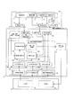
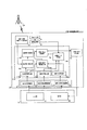
図1は、本発明の実施例1に係る映像・地図連動システムの全体構成を示す図である。この映像・地図連動システムは、複数の利用端末51と、少なくとも一つのカメラ31と、利用端末51及びカメラ31に、通信ネットワークを介して接続された映像・地図情報処理サーバー41とを備える。なお、図1では、複数の利用端末51のうち一つの利用端末51のみが図示されている。また、利用端末51は一つであってもよい。   FIG. 1 is a diagram illustrating an overall configuration of a video / map linkage system according to a first embodiment of the present invention. This video / map link system includes a plurality of usage terminals 51, at least one camera 31, and a video / map information processing server 41 connected to the usage terminals 51 and 31 via a communication network. In FIG. 1, only one usage terminal 51 among the plurality of usage terminals 51 is illustrated. Moreover, the number of the use terminals 51 may be one.

利用端末51は、入出力インターフェイス、CPU(中央演算処理装置)、記憶装置等(以上、特に図示せず)を備えており、入力部19及び表示部20が設けられた通常のパーソナルコンピューター(パソコン)である。   The use terminal 51 includes an input / output interface, a CPU (Central Processing Unit), a storage device and the like (not shown in particular), and is a normal personal computer (personal computer) provided with the input unit 19 and the display unit 20. ).

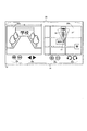
図2は、利用端末51の画面52の一例を具体的に示した図である。利用端末51の画面52には、表示部20として、映像表示部20aと地図表示部20bとが並んで示されている。映像表示部20aはカメラ31で撮影された映像を表示し、地図表示部20bは、この映像に対応した(連動した)地図を表示する。   FIG. 2 is a diagram specifically illustrating an example of the screen 52 of the use terminal 51. On the screen 52 of the use terminal 51, as the display unit 20, a video display unit 20a and a map display unit 20b are shown side by side. The video display unit 20a displays a video taken by the camera 31, and the map display unit 20b displays a map corresponding (linked) to this video.

本発明の特徴の一つは、撮影された映像と対応して表示させた地図上に、撮影の方向、撮影の視野範囲等、この映像(映像データ)に関する撮影情報を地図(地図データ)上に反映させていることである。   One of the features of the present invention is that on a map displayed in correspondence with a captured video, shooting information regarding the video (video data) such as a shooting direction and a shooting visual field range is displayed on the map (map data). It is reflected in.

具体的には、地図表示部20bでは、地図上における(表示された)カメラ31’の位置を中心にして扇形の撮影の視野範囲37’が表示されている。カメラ31’の位置から撮影された映像の焦点、言い換えれば、地図上における撮影対象物の位置までが矢印36で表されている。つまり、カメラ31’の位置から延びる矢印36の先端にこの撮影対象物が位置している。矢印36の長さl(エル)は、カメラ31’の位置から撮影対象物の位置までの、この地図上における距離を表す。   Specifically, the map display unit 20b displays a fan-shaped field-of-view range 37 'centered on the position of the camera 31' (displayed) on the map. The focus of the image taken from the position of the camera 31 ′, in other words, the position of the object to be photographed on the map is represented by an arrow 36. That is, the object to be photographed is located at the tip of the arrow 36 extending from the position of the camera 31 '. The length l (el) of the arrow 36 represents the distance on the map from the position of the camera 31 'to the position of the object to be photographed.

画面52上には、表示部20と共に、入力部19が示されている。入力部19は、映像表示部20aに表示された映像を拡大又は縮小する倍率変更についての操作入力ボタン19aと、映像表示部20aに表示された映像の方向を操作する操作入力ボタン19bと、地図表示部20bに表示された地図を拡大又は縮小する倍率変更についての操作入力ボタン19cと、地図表示部20bに表示された地図の方向を操作する操作入力ボタン19dとを有する。   On the screen 52, the input unit 19 is shown together with the display unit 20. The input unit 19 includes an operation input button 19a for changing the magnification for enlarging or reducing the image displayed on the image display unit 20a, an operation input button 19b for operating the direction of the image displayed on the image display unit 20a, and a map An operation input button 19c for changing the magnification for enlarging or reducing the map displayed on the display unit 20b and an operation input button 19d for operating the direction of the map displayed on the map display unit 20b are provided.

操作入力ボタン19a、19cのうち、+の印が付けられた操作入力ボタンは、それぞれ映像又は地図を拡大するときに操作し、−の印が付けられた操作入力ボタンは、それぞれ映像又は地図を縮小するときに操作する。操作入力ボタン19bのうち、図2の紙面に向かって右側の操作入力ボタンは、映像表示部20aに表示されている映像を基準にして、さらに右方向の映像を見たい場合に操作し、図2の紙面に向かって左側の操作入力ボタンは、さらに左方向の映像を見たい場合に操作する。   Among the operation input buttons 19a and 19c, the operation input buttons marked with + are operated when enlarging the image or the map, respectively, and the operation input buttons marked with − are respectively displayed with the image or map. Operate when shrinking. Of the operation input buttons 19b, the operation input button on the right side of the drawing in FIG. 2 is operated when it is desired to view a video in the right direction with reference to the video displayed on the video display unit 20a. The operation input button on the left side of the second page is operated when it is desired to view a video image in the left direction.

一方、操作入力ボタン19dのうち、図2の紙面に向かって右側の操作入力ボタンは、地図表示部20bに表示されている地図上のカメラ31’の視野範囲37’を基準にして、この視野範囲37’よりもさらに右周り方向にある視野範囲(映像表示部20aで表示されている映像のさらに右方向の映像に対応する)を見たい場合に操作する。同様に、操作入力ボタン19dのうち、図2の紙面に向かって左側の操作入力ボタンは、地図上に示されているカメラ31’の視野範囲37’よりもさらに左周り方向にある視野範囲(映像表示部20aで表示されている映像のさらに左方向の映像に対応する)を見たい場合に操作する。   On the other hand, among the operation input buttons 19d, the operation input button on the right side of the page of FIG. 2 has the field of view 37 ′ of the camera 31 ′ on the map displayed on the map display unit 20b as a reference. This operation is performed when it is desired to view the visual field range (corresponding to the video image in the further right direction of the video image displayed on the video display unit 20a) in the clockwise direction from the range 37 ′. Similarly, among the operation input buttons 19d, the operation input button on the left side of the paper surface of FIG. 2 has a field-of-view range that is further to the left than the field-of-view range 37 ′ of the camera 31 ′ shown on the map ( This operation is performed when the user wants to see the video displayed on the video display unit 20a (corresponding to a video in the left direction).

なお、本実施例では、入力部19として利用端末51の画面52上に操作入力ボタン19a〜19dを設けているが、同様の操作を利用端末51に接続される例えばキーボードから入力することにしてもよい。   In this embodiment, the operation input buttons 19a to 19d are provided on the screen 52 of the usage terminal 51 as the input unit 19, but the same operation is input from, for example, a keyboard connected to the usage terminal 51. Also good.

再び、図1を参照して、カメラ31は、遠隔地に設けられる定点カメラ(ライブカメラ)である。カメラ31は、例えば、ニュースや音楽、買い物・観光等の情報を映像で配信するためや、防犯、災害対策等の監視カメラとして利用され得る。なお、実施例1ではカメラ31として、例えば自動焦点機能を有するカメラを用いている。また、カメラ31は、パン、PAN機能(左右方向にカメラが首振り状に回る機能)及びチルト、TILT機能(上下方向にカメラが首振り状に動く機能)を有する。   Referring to FIG. 1 again, the camera 31 is a fixed point camera (live camera) provided at a remote place. The camera 31 can be used, for example, to distribute information such as news, music, shopping / tourism, etc. as video, or as a surveillance camera for crime prevention, disaster countermeasures, and the like. In the first embodiment, as the camera 31, for example, a camera having an autofocus function is used. In addition, the camera 31 has a pan and PAN function (a function in which the camera rotates in a horizontal direction) and a tilt and TILT function (a function in which the camera moves in a vertical direction).

なお、カメラとして、自動焦点機能を有さずに、360度全方位において映像データの取得を可能とする全方位撮影型のカメラ(後述する実施例2参照)を用いても良い。また、実施例1の自動焦点機能を有する(全方位型でない)カメラ31と、後述する実施例2の全方位撮影型のカメラとを組合わせて複数用いてもよい。   Note that an omnidirectional camera (see Example 2 to be described later) that can acquire video data in 360 ° omnidirectional without having an autofocus function may be used as the camera. Further, a plurality of cameras 31 (not omnidirectional) having the autofocus function of the first embodiment and omnidirectional photographing cameras of the second embodiment described later may be used in combination.

自動焦点機能を有する実施例1の31カメラは、信号入力部7と、受信された信号を制御する制御部5と、映像撮影部1と、映像出力部6と、信号出力部8と、を備える。そして、映像撮影部1は、焦点計測部2、方向計測部3、及び角度計測部4を有する。   The 31 camera according to the first embodiment having the autofocus function includes a signal input unit 7, a control unit 5 that controls a received signal, a video shooting unit 1, a video output unit 6, and a signal output unit 8. Prepare. The video photographing unit 1 includes a focus measuring unit 2, a direction measuring unit 3, and an angle measuring unit 4.

信号入力部7は、例えば通信ネットワークを介してカメラ31と接続された映像・地図情報処理サーバー41からの信号を受信する。制御部5は、受信された信号に基づき映像撮影部1を制御する。映像撮影部1は、この信号に基づき所望の映像を撮影する。撮影の際には、映像撮影部1において、焦点計測部2、方向計測部3、角度計測部4は、それぞれ、カメラ31で撮影される撮影対象物までの焦点距離、方向、角度を計測する。映像出力部6は、撮影された撮影対象物を含む映像データを映像・地図情報処理サーバー41に通信ネットワークを介して送信する。信号出力部8は、撮影対象物について計測された、これらの焦点距離、方向、角度についての計測値のデータを、映像データに関する撮影情報として、同様に映像・地図情報処理サーバー41に通信ネットワークを介して送信する。   The signal input unit 7 receives a signal from the video / map information processing server 41 connected to the camera 31 via, for example, a communication network. The control unit 5 controls the video photographing unit 1 based on the received signal. The video imaging unit 1 captures a desired video based on this signal. At the time of shooting, in the video shooting unit 1, the focus measuring unit 2, the direction measuring unit 3, and the angle measuring unit 4 respectively measure the focal length, direction, and angle to the shooting target imaged by the camera 31. . The video output unit 6 transmits the video data including the photographed subject to the video / map information processing server 41 via the communication network. Similarly, the signal output unit 8 uses the measurement data of the focal length, direction, and angle measured for the object to be photographed as shooting information about the video data to connect the communication network to the video / map information processing server 41. Send through.

映像・地図情報処理サーバー41は、映像入力部9と、信号出力部10と、信号入力部11と、映像変換(処理)部12と、地図・映像位置データ記憶部13と、映像・地図同期処理部14と、映像・地図出力部15と、操作認識部21と、を備える。   The video / map information processing server 41 includes a video input unit 9, a signal output unit 10, a signal input unit 11, a video conversion (processing) unit 12, a map / video position data storage unit 13, and a video / map synchronization. A processing unit 14, a video / map output unit 15, and an operation recognition unit 21 are provided.

操作認識部21は、利用端末51からの入力に基づき映像又は地図についての操作入力信号を映像・地図同期処理部14に送る。具体的には、操作認識部21は、倍率変更認識部16と、カメラ方向変更認識部17と、地図方向変更(操作)認識部18と、を有する。   The operation recognition unit 21 sends an operation input signal for a video or a map to the video / map synchronization processing unit 14 based on an input from the use terminal 51. Specifically, the operation recognition unit 21 includes a magnification change recognition unit 16, a camera direction change recognition unit 17, and a map direction change (operation) recognition unit 18.

倍率変更認識部16は、利用端末51の入力部19から入力される、映像データ又は地図データを拡大又は縮小する倍率変更についての指示に基づき、その操作入力信号を映像・地図同期処理部14に送る。具体的には、図2に示されるように、映像表示部20aに表示された映像を参照して映像データの拡大又は縮小についての指示、もしくは地図表示部20bに表示された地図を参照して地図の拡大又は縮小についての指示が、それぞれ操作入力ボタン19a、19cにより行われる。すると、この操作入力ボタン19a、19cにより行われた拡大又は縮小の倍率変更についての指示入力量が定量化(数値データ化)されて操作入力信号として映像・地図同期処理部14に送られる。   The magnification change recognizing unit 16 inputs the operation input signal to the video / map synchronization processing unit 14 based on the instruction about the magnification change for enlarging or reducing the video data or the map data input from the input unit 19 of the use terminal 51. send. Specifically, as shown in FIG. 2, referring to the video displayed on the video display unit 20a, an instruction for enlarging or reducing the video data, or referring to the map displayed on the map display unit 20b. An instruction for enlarging or reducing the map is given by the operation input buttons 19a and 19c, respectively. Then, the instruction input amount for the enlargement or reduction magnification change performed by the operation input buttons 19a and 19c is quantified (numerical data) and sent to the video / map synchronization processing unit 14 as an operation input signal.

カメラ方向変更認識部17は、利用端末51の入力部19から入力される、映像データの方向についての指示に基づき、その操作入力信号を映像・地図同期処理部14に送る。具体的には、図2に示されるように、映像表示部20aに表示された映像を基に、見たい方向についての指示入力が操作入力ボタン19bにより行われる。すると、操作入力ボタン19bにより行われた入力量が定量化(数値データ化)されて操作入力信号として映像・地図同期処理部14に送られる。   The camera direction change recognizing unit 17 sends the operation input signal to the video / map synchronization processing unit 14 based on an instruction about the direction of the video data input from the input unit 19 of the use terminal 51. Specifically, as shown in FIG. 2, based on the video displayed on the video display unit 20a, an instruction input regarding a desired direction is performed by the operation input button 19b. Then, the input amount performed by the operation input button 19b is quantified (numerical data) and sent to the video / map synchronization processing unit 14 as an operation input signal.

地図方向変更(操作)認識部18は、利用端末51の入力部19から入力される、地図についての操作入力信号を映像・地図同期処理部14に送る。具体的には、地図表示部20bに表示された視野範囲37’を基に、さらに見たい視野範囲の方向についての指示が、操作入力ボタン19dにより行われる。すると、操作入力ボタン19dにより行われた入力量が、上記と同様にして定量化(数値データ化)されて操作入力信号として映像・地図同期処理部14に送られる。   The map direction change (operation) recognizing unit 18 sends an operation input signal for a map input from the input unit 19 of the use terminal 51 to the video / map synchronization processing unit 14. Specifically, based on the visual field range 37 ′ displayed on the map display unit 20 b, an instruction about the direction of the visual field range to be further viewed is given by the operation input button 19 d. Then, the input amount made by the operation input button 19d is quantified (numerical data) in the same manner as described above and sent to the video / map synchronization processing unit 14 as an operation input signal.

利用端末51から送られてきたこれらの操作入力信号はそれぞれ、映像・地図同期処理部14で映像を撮影するための信号に変換された後、信号出力部10から、通信ネットワークを介してカメラ31内に送信される。   Each of these operation input signals sent from the user terminal 51 is converted into a signal for photographing a video by the video / map synchronization processing unit 14, and then from the signal output unit 10 through the communication network to the camera 31. Sent in.

映像入力部9は、カメラ31で撮影された映像データを、通信ネットワークを介してデジタル信号として受信する。映像変換(処理)部12は、このデジタル信号を映像入力部9から受け取り映像データに変換した後、映像・地図同期処理部14へ送る。   The video input unit 9 receives video data captured by the camera 31 as a digital signal via a communication network. The video conversion (processing) unit 12 receives this digital signal from the video input unit 9, converts it into video data, and sends it to the video / map synchronization processing unit 14.

信号入力部11は、カメラ31で撮影された映像データに関する撮影情報、具体的には例えば、カメラ31内の信号出力部8から送信される、撮影の際の映像についての焦点距離の計測値、方向の計測値、及び、角度の計測値についてのデータを受信し、映像・地図同期処理部14に送る。   The signal input unit 11 is shooting information related to video data shot by the camera 31, specifically, for example, a measurement value of a focal length of a video at the time of shooting transmitted from the signal output unit 8 in the camera 31, Data on the direction measurement value and the angle measurement value is received and sent to the video / map synchronization processing unit 14.

一方、地図・映像位置データ記憶部13は、少なくとも、設置されているカメラ31の位置データ(カメラ31の位置についてのデータ、例えばカメラ31の位置座標データ)を、地図データに対応させて記憶している。つまり、カメラ31の位置データと、地図データ上におけるカメラ31’の位置データとを対応させて記憶している。   On the other hand, the map / video position data storage unit 13 stores at least position data of the installed camera 31 (data on the position of the camera 31, for example, position coordinate data of the camera 31) in association with the map data. ing. That is, the position data of the camera 31 and the position data of the camera 31 'on the map data are stored in association with each other.

さらには、地図・映像位置データ記憶部13に、カメラ31で撮影される撮影対象物の地図データ上における位置(撮影対象物の位置データ、例えば撮影対象物の位置座標データ)と、この撮影対象物の位置データに対応させて、その撮影対象物についての情報を記憶させておいてもよい。地図データ上における撮影対象物についての情報としては、例えば、その撮影対象物が建物の場合、建物の名称、建物の所在地の住所、建物が有しているホームページのアドレス等の建物についての情報が挙げられる。また、その撮影対象物が山等の景色の場合であっても、同様に、その山の名称、その山の所在地の住所、その山への行き方、その山についての情報が掲載されているホームページのアドレス等の情報が挙げられる。   Further, in the map / video position data storage unit 13, the position on the map data of the object to be photographed by the camera 31 (position data of the object to be photographed, for example, position coordinate data of the object to be photographed), and the object to be photographed Information about the object to be photographed may be stored in association with the position data of the object. As information about the object to be photographed on the map data, for example, when the object to be photographed is a building, information on the building such as the name of the building, the address of the building location, and the address of the homepage that the building has is included. Can be mentioned. In addition, even if the object to be photographed is a landscape such as a mountain, the homepage where the name of the mountain, the address of the mountain location, how to get to the mountain, and information about the mountain are also posted. Information such as the address.

なお、またさらに、地図・映像位置データ記憶部13に、カメラ31で撮影される撮影対象物の撮影画面上における位置データ、つまり、カメラ31の映像撮影部1の撮影画面を座標に見立て、この座標に見立てた撮影画面上における撮影対象物の位置データと、地図データ上における撮影対象物の位置データとを予め対応づけて記憶させておくことにしてもよい。   Still further, the map / video position data storage unit 13 uses the coordinates of the position data on the shooting screen of the shooting object shot by the camera 31, that is, the shooting screen of the video shooting unit 1 of the camera 31. The position data of the object to be imaged on the image capturing screen based on the coordinates may be stored in advance in association with the position data of the object to be imaged on the map data.

映像・地図同期処理部14では、映像変換(処理)部12から送られてきた映像データと、地図・映像位置データ記憶部13に記憶されている地図データとを連動させる。つまり、映像・地図同期処理部14は、カメラ31で撮影された撮影対象物を含む映像データを、映像変換(処理)部12を経て取得すると共に、この映像データに対応する地図データを地図・映像位置データ記憶部13から取得する。それと同時に、信号入力部11から送られてきた撮影方向、撮影の視野範囲、撮影の中心点、撮影の倍率等の映像データに関する撮影情報を取得した地図データに反映させる。このような映像・地図同期処理部14の構成及び動作については、さらに詳しく後述する。   The video / map synchronization processing unit 14 links the video data sent from the video conversion (processing) unit 12 with the map data stored in the map / video position data storage unit 13. In other words, the video / map synchronization processing unit 14 obtains video data including a subject to be photographed by the camera 31 via the video conversion (processing) unit 12 and maps the map data corresponding to the video data to the map / map. Obtained from the video position data storage unit 13. At the same time, the shooting information regarding the video data such as the shooting direction, the shooting field of view range, the shooting center point, and the shooting magnification sent from the signal input unit 11 is reflected in the acquired map data. The configuration and operation of the video / map synchronization processing unit 14 will be described in more detail later.

映像・地図出力部15は、映像・地図同期処理部14から送られてきた上記の映像データと、この映像データに連動する地図データとを受け取り、利用端末51に出力送信する。   The video / map output unit 15 receives the video data sent from the video / map synchronization processing unit 14 and the map data linked to the video data, and outputs the data to the use terminal 51.

上述した映像・地図同期処理部14において、映像データと地図データとを連動させる方法(要するに、取得した映像データに関する撮影情報を、映像データと対応して取得した地図データ上に反映させる方法、映像・地図連動方法)として、例えば以下の方法がある。その方法は、少なくとも、カメラ31の位置からカメラ31で撮影される撮影対象物の位置までの平面上(水平面上)における距離を、カメラ31の位置に基づいて算出し、この算出された平面上における距離から、地図データ上におけるカメラの位置に基づいて撮影対象物の位置を特定する映像・地図連動方法である。つまり、この映像・地図連動方法では、カメラ31の位置に基づいてカメラ31の位置から撮影対象物の位置までの平面上における距離を算出する。この算出された平面上における距離に対応して、地図データ上におけるカメラの位置からの距離が求められる。地図データ上において、カメラの位置からの距離が求められことにより、その距離の先端に位置する撮影対象物の位置が特定されるのである。そして、特定された地図データ上における撮影対象物の位置を基に、撮影対象物を含む映像データに関する撮影情報を地図データ上に反映させる(表示、図示する)。   In the video / map synchronization processing unit 14 described above, a method of linking video data and map data (in short, a method of reflecting shooting information relating to acquired video data on map data acquired in association with video data, video -As a map interlocking method), for example, there are the following methods. In this method, at least a distance on a plane (on a horizontal plane) from the position of the camera 31 to the position of the object to be photographed by the camera 31 is calculated based on the position of the camera 31, and the calculated plane is calculated. This is a video / map interlocking method that specifies the position of an object to be photographed based on the position of the camera on the map data based on the distance at. That is, in this video / map linkage method, the distance on the plane from the position of the camera 31 to the position of the object to be photographed is calculated based on the position of the camera 31. Corresponding to the calculated distance on the plane, the distance from the camera position on the map data is obtained. By obtaining the distance from the camera position on the map data, the position of the object to be photographed located at the tip of the distance is specified. Then, based on the position of the shooting target on the specified map data, shooting information relating to video data including the shooting target is reflected on the map data (displayed and illustrated).

実施例1では、図1に示される映像・地図同期処理部14の構成、及び、上記映像・地図連動方法を用いた映像・地図同期システムの動作を以下に詳しく説明する。映像・地図同期処理部14は、視野算出部14aと、カメラ倍率算出部14bと、地図倍率算出部14cと、カメラ方向算出部14dと、地図方向算出部14eと、地図再生処理部14fと、映像・地図同期部14gと、を有する。   In the first embodiment, the configuration of the video / map synchronization processing unit 14 shown in FIG. 1 and the operation of the video / map synchronization system using the video / map synchronization method will be described in detail below. The video / map synchronization processing unit 14 includes a visual field calculation unit 14a, a camera magnification calculation unit 14b, a map magnification calculation unit 14c, a camera direction calculation unit 14d, a map direction calculation unit 14e, a map reproduction processing unit 14f, And a video / map synchronization unit 14g.

カメラ倍率算出部14bは、倍率変更認識部16から受け取った映像又は地図を拡大又は縮小する倍率変更についての操作入力信号を基に、この倍率変更率を数値データ化する。   The camera magnification calculation unit 14b converts the magnification change rate into numerical data based on an operation input signal for magnification change for enlarging or reducing the image or map received from the magnification change recognition unit 16.

地図倍率算出部14cは、カメラ倍率算出部14bで数値データ化された地図の倍率変更率に基づいて、地図・映像位置データ記憶部13から所望の倍率の地図データを取得する。   The map magnification calculation unit 14c acquires map data of a desired magnification from the map / video position data storage unit 13 based on the map magnification change rate converted into numerical data by the camera magnification calculation unit 14b.

カメラ方向算出部14dは、カメラ方向認識部17から受け取った映像の方向についての操作入力信号を基に、カメラ31を実際に動かす(映像を撮影する)ためのデータ(信号)に変換して信号出力部10に送る。また、この変換された映像を撮影するためのデータは、対応する数値データ化された地図上の視野範囲の方向変更率に変換され、地図方向算出部14eに送られる。   The camera direction calculation unit 14d converts the signal into data (signal) for actually moving the camera 31 (capturing the video) based on the operation input signal regarding the video direction received from the camera direction recognition unit 17. Send to output unit 10. Further, the data for photographing the converted video is converted into the direction change rate of the field-of-view range on the map converted into corresponding numerical data, and sent to the map direction calculation unit 14e.

地図方向算出部14eは、地図方向変更(操作)認識部18から受け取った地図についての操作入力信号(地図上における撮影対象物の方向変更についての操作入力信号)を基に、この方向変更率を数値データ化する。また、この数値データ化された方向変更率は、カメラ方向算出部14dに送られる。カメラ方向算出部14dでは、送られてきた撮影対象物の方向変更率に対応して、映像を撮影するためのデータに変換される。   The map direction calculation unit 14e calculates the direction change rate based on the operation input signal for the map received from the map direction change (operation) recognition unit 18 (the operation input signal for the direction change of the shooting target on the map). Convert to numerical data. The direction change rate converted into numerical data is sent to the camera direction calculation unit 14d. In the camera direction calculation unit 14d, the camera direction calculation unit 14d converts the data to be used for shooting a video in accordance with the direction change rate of the shooting target.

視野算出部14aは、カメラ31内の焦点計測部2及び角度計測部4において計測された数値データより、カメラ31の位置から映像の焦点Fとなる撮影対象物32までの地上の平面上における距離Lを算出する(後述する図3参照)。さらに、視野算出部14aは、算出された距離Lと、カメラ倍率算出部14bで数値データ化された映像(カメラ)の倍率変更率とから、距離Lに対応する地図上における距離l(エル)を算出する。さらに、視野算出部14aは、この距離l(エル)や、カメラ倍率算出部14bで数値データ化された倍率変更率や、地図方向算出部14eで数値データ化された方向変更率から、視野の範囲を導き出す(視野の範囲を規定する新たな境界線を算出する)。   The field-of-view calculation unit 14a calculates the distance on the ground plane from the position of the camera 31 to the photographing object 32 that is the focal point F of the image based on the numerical data measured by the focus measurement unit 2 and the angle measurement unit 4 in the camera 31. L is calculated (see FIG. 3 described later). Further, the visual field calculation unit 14a calculates the distance l (el) on the map corresponding to the distance L from the calculated distance L and the magnification change rate of the video (camera) converted into numerical data by the camera magnification calculation unit 14b. Is calculated. Further, the visual field calculation unit 14a calculates the visual field from the distance l (el), the magnification change rate converted into numerical data by the camera magnification calculation unit 14b, and the direction change rate converted into numerical data by the map direction calculation unit 14e. Deriving a range (calculating a new boundary that defines the range of the field of view).

地図再生処理部14fは、地図倍率算出部14cにより地図・映像データ記憶部13から倍率変更率に応じて取得された地図データに、視野算出部14aで算出された地図上に表示すべき、距離lを有し撮影対象物を示す矢印や、視野の範囲を規定する新たな境界線を図示する。即ち、地図再生処理部14fでは、撮影方向、視野の範囲、撮影対象物(撮影の中心点、映像の焦点)、撮影の倍率等の撮影データに関する撮影情報が反映された地図データが再生される。   The map reproduction processing unit 14f displays the distance to be displayed on the map calculated by the visual field calculation unit 14a on the map data acquired according to the magnification change rate from the map / video data storage unit 13 by the map magnification calculation unit 14c. An arrow having l and indicating an object to be imaged and a new boundary line defining the range of the field of view are illustrated. That is, the map reproduction processing unit 14f reproduces map data reflecting photographing information relating to photographing data such as a photographing direction, a field of view range, a photographing target (a photographing central point, a video focal point), and a photographing magnification. .

映像・地図同期部14gは、地図再生処理部14fで再生された撮影情報が反映された地図データと、映像変換部12から送られてきた映像データとを同期させる。同期された映像データと地図データとは、映像・地図出力部15から出力され、利用端末51に送信され、表示部20に表示される。   The video / map synchronization unit 14g synchronizes the map data reflecting the shooting information reproduced by the map reproduction processing unit 14f with the video data sent from the video conversion unit 12. The synchronized video data and map data are output from the video / map output unit 15, transmitted to the use terminal 51, and displayed on the display unit 20.

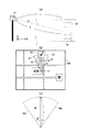
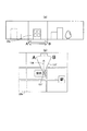
上述した映像データと地図データとを連動させる映像・地図連動方法について、以下にさらに詳述する。図3(a)は、視野算出部14aにおいて、カメラ31の位置から映像の焦点Fとなる撮影対象物32の位置までの地上の平面上における距離Lを算出する原理を示す図であり、図3(b)は、撮影された映像データと連動して地図データが表示された地図表示部20bを示す図である。   The video / map linkage method for linking the video data and map data described above will be described in further detail below. FIG. 3A is a diagram illustrating the principle of calculating the distance L on the ground plane from the position of the camera 31 to the position of the photographing object 32 to be the focal point F of the image in the visual field calculation unit 14a. 3 (b) is a diagram showing a map display unit 20b on which map data is displayed in conjunction with photographed video data.

ここで、図3(a)に示されるように、地上の平面をXY平面とし、初期状態として所定の倍率に設定された撮影条件において、カメラ31の位置から撮影対象物32の位置までの焦点距離をf、焦点距離fとXY平面とが成す角度をθとする。すると、視野算出部14aでは、カメラ31の位置から撮影対象物32の位置までのXY平面上における距離Lは、L=f×cosθとして算出される。算出された距離Lに対応して、初期状態において設定されカメラ倍率算出部14bで数値データ化された倍率(倍率変更率)を基に、地図データ上におけるカメラ31’の位置から撮影対象物32’の位置までの距離l(エル)が設定(算出)される。つまり、地図データ上における撮影対象物32’の位置が特定されるのである。なお、設定された距離lは、図3(b)の地図表示部20bでは、地図上においてカメラ31’の位置から撮影対象物32’の位置に向かう長さ(距離)lを有する矢印36として表示される。   Here, as shown in FIG. 3 (a), the focal point from the position of the camera 31 to the position of the object to be photographed 32 under the photographing condition in which the ground plane is the XY plane and is set to a predetermined magnification as an initial state. Let f be the distance, and θ be the angle between the focal length f and the XY plane. Then, in the visual field calculation unit 14a, the distance L on the XY plane from the position of the camera 31 to the position of the photographing object 32 is calculated as L = f × cos θ. Corresponding to the calculated distance L, based on the magnification (magnification change rate) set in the initial state and converted into numerical data by the camera magnification calculator 14b, the shooting object 32 is determined from the position of the camera 31 'on the map data. A distance l (el) to the position of 'is set (calculated). That is, the position of the photographing object 32 'on the map data is specified. Note that the set distance l is indicated by an arrow 36 having a length (distance) l from the position of the camera 31 ′ to the position of the object 32 ′ on the map in the map display unit 20 b of FIG. Is displayed.

さらに視野算出部14aは、地図表示部20bにおいて表示されるべき視野の範囲を設定する(導き出す)。つまり、既に述べたように、算出された距離lと、例えば初期状態において設定され地図方向算出部14eで数値データ化された方向(方向変更率)とから、地図上の視野の範囲37’を規定する境界線が算出(設定)される。つまり、視野範囲37’は、図3(b)に示されるように、視野の境界線33、34と円弧35とで囲まれた円弧状図形(扇形図形)である。ここで、視野の境界線33、34が成す角をαとする。なお、円弧35の中心には、撮影の中心点、つまり地図上において映像の焦点F’となる撮影対象物32’が位置している。   Furthermore, the visual field calculation unit 14a sets (leads out) a range of visual fields to be displayed on the map display unit 20b. That is, as described above, the visual field range 37 ′ on the map is calculated from the calculated distance l and, for example, the direction (direction change rate) set in the initial state and converted into numerical data by the map direction calculation unit 14e. A prescribed boundary line is calculated (set). That is, as shown in FIG. 3B, the visual field range 37 'is an arcuate figure (fan figure) surrounded by the visual field boundary lines 33 and 34 and the arc 35. Here, the angle formed by the boundary lines 33 and 34 of the visual field is α. Note that, at the center of the arc 35, a photographing center point, that is, a photographing object 32 'serving as a focal point F' of the image on the map is located.

上記のように視野算出部14aで算出された地図上に図示すべき距離l(エル)や視野範囲37’、撮影の中心点(撮影対象物の位置)32’、撮影の倍率等の映像データに関する撮影情報は、地図再生処理部14fにおいて地図データに反映される。さらに、地図データ上において特定された撮影対象物32’の位置(位置データ)を基に、撮影対象物32’の名称や住所等といった撮影対象物32’についての情報を含む映像データに関する撮影情報が、地図データ上に表示させることができる。撮影情報が反映された地図データは、地図・映像同期部14gで対応する映像データと同期され、同期された映像データと地図データとは、映像・地図出力部15を介して利用端末51に送信され、表示部20に表示される。   Image data such as the distance l (el) to be shown on the map calculated by the visual field calculation unit 14a as described above, the visual field range 37 ', the photographing center point (position of the photographing object) 32', and the photographing magnification. The shooting information related to is reflected in the map data in the map reproduction processing unit 14f. Further, based on the position (position data) of the shooting target 32 ′ specified on the map data, shooting information related to video data including information about the shooting target 32 ′ such as the name and address of the shooting target 32 ′. Can be displayed on the map data. The map data reflecting the shooting information is synchronized with the corresponding video data in the map / video synchronization unit 14g, and the synchronized video data and map data are transmitted to the user terminal 51 via the video / map output unit 15. And displayed on the display unit 20.

なお、少なくとも撮影対象物についての情報を含む映像データに関する撮影情報は、地図データ上に反映(表示)させると共に、利用端末51から音声出力させることにしてもよい。   Note that shooting information related to video data including at least information about the shooting target may be reflected (displayed) on the map data and may be output from the user terminal 51 as a sound.

次に、利用端末51から例えば映像を拡大又は縮小する倍率変更についての新たな操作入力、続いて、地図上における撮影の視野範囲(撮影対象物の方向)を変更する新たな操作入力が行われたとする。この場合、まず、カメラ倍率算出部14bは、倍率変更認識部16から受け取った映像データを拡大又は縮小する倍率変更率についての操作入力信号を基に、この映像の倍率変更率を数値データ化する。そして、カメラ倍率算出部14bは、映像についての数値データ化された倍率変更率と対応する地図についての倍率変更率を算出する。   Next, for example, a new operation input for changing the magnification for enlarging or reducing the image is performed from the use terminal 51, and then a new operation input for changing the field of view of the image on the map (the direction of the object to be imaged) is performed. Suppose. In this case, first, the camera magnification calculation unit 14b converts the magnification change rate of the video into numerical data based on an operation input signal regarding the magnification change rate for enlarging or reducing the video data received from the magnification change recognition unit 16. . Then, the camera magnification calculation unit 14b calculates the magnification change rate for the map corresponding to the magnification change rate converted into numerical data for the video.

なお、本実施例では、対応する地図についての倍率変更率の算出を、カメラ倍率算出部14bで行っているが、地図倍率算出部14cが、カメラ倍率算出部14bで算出された映像についての倍率変更率を基に、地図についての倍率変更率を算出することにしてもよい。   In this embodiment, the magnification change rate for the corresponding map is calculated by the camera magnification calculator 14b. However, the map magnification calculator 14c calculates the magnification for the video calculated by the camera magnification calculator 14b. You may decide to calculate the magnification change rate about a map based on a change rate.

一方、地図方向算出部14eは、地図方向変更(操作)認識部18から受け取った地図上における撮影の視野範囲(例えば撮影対象物の方向)を変更する新たな操作入力信号を基に、撮影対象物の方向変更率を数値データ化する。言い換えれば、地図方向算出部14eは、数値データ化した方向変更率(図2に示した矢印36の方向についての移動量)を算出し、視野算出部14aに送る。   On the other hand, the map direction calculation unit 14e is based on a new operation input signal for changing the field-of-view range (for example, the direction of the shooting target) on the map received from the map direction change (operation) recognition unit 18. Convert the direction change rate of objects into numerical data. In other words, the map direction calculation unit 14e calculates the direction change rate (the amount of movement in the direction of the arrow 36 shown in FIG. 2) converted into numerical data and sends it to the visual field calculation unit 14a.

地図倍率算出部14cは、カメラ倍率算出部14bで算出された地図についての倍率変更率に基づいて、地図・映像位置データ記憶部13からこの倍率変更率に対応する地図データを取得する。そして、視野算出部14aは、カメラ倍率算出部14bで算出された地図についての倍率変更率や地図方向算出部14eで算出された撮影対象物の方向変更率を基に、利用端末51の画面52上に表示する地図データ上の視野範囲を規定する新たな境界線を算出するのである。   The map magnification calculation unit 14c acquires map data corresponding to the magnification change rate from the map / video position data storage unit 13 based on the magnification change rate for the map calculated by the camera magnification calculation unit 14b. The field-of-view calculation unit 14a then uses the screen 52 of the user terminal 51 based on the magnification change rate for the map calculated by the camera magnification calculation unit 14b and the direction change rate of the shooting target calculated by the map direction calculation unit 14e. A new boundary line that defines the visual field range on the map data displayed above is calculated.

ここで、地図データ上の視野範囲を規定する新たな境界線を算出する原理について具体的に以下に説明する。倍率が変更された新たな地図データを地図・映像位置データ記憶部13から取得する場合、その倍率の変化率をpとする。すると、地図再生処理部14fは、倍率変更率pに対応して拡大又は縮小された(倍率を変更した)地図を地図・映像位置データ記憶部13から取得する。なお、倍率変更されると、実際の映像において、カメラ31の位置から焦点Fとなる撮影対象物の位置までの平面上における距離Lは変化するが、上記のように倍率変更率pに対応して拡大又は縮小された地図を取得するので、地図上に距離lとして表示される矢印36の長さ自体は変化しない。(同様に、地図上に表示される視野の境界線33、34の長さ自体も、変化しない。)   Here, the principle of calculating a new boundary line that defines the visual field range on the map data will be specifically described below. When new map data whose magnification has been changed is acquired from the map / video position data storage unit 13, the rate of change of the magnification is assumed to be p. Then, the map reproduction processing unit 14 f acquires from the map / video position data storage unit 13 a map that has been enlarged or reduced (the magnification has been changed) in accordance with the magnification change rate p. When the magnification is changed, the distance L on the plane from the position of the camera 31 to the position of the subject to be focused F changes in the actual video, but it corresponds to the magnification change rate p as described above. Therefore, the length of the arrow 36 displayed as the distance l on the map does not change. (Similarly, the lengths of the boundary lines 33 and 34 of the visual field displayed on the map do not change.)

倍率変更されて取得された地図上において、新たな視野の境界線33a、34aが成す角度をα’とすると、角度α’は、以下の式(1)で表される。   On the map acquired by changing the magnification, if the angle formed by the boundary lines 33a and 34a of the new visual field is α ′, the angle α ′ is expressed by the following equation (1).

α’=α/p (1)         α ′ = α / p (1)

式(1)より、新たに規定される視野の境界線33a、34aが成す角度α’が求められる。図3(c)に、新たに規定される視野の範囲、つまり、視野の境界線33a、34a及び視野の境界線33a、34aが成す角度α’が表示される模式的な図を示す。   From the expression (1), the angle α ′ formed by the newly defined visual field boundary lines 33a and 34a is obtained. FIG. 3C is a schematic diagram in which the range of the newly defined visual field, that is, the visual field boundary lines 33a and 34a and the angle α ′ formed by the visual field boundary lines 33a and 34a are displayed.

さらに、地図データ上における撮影の方向(撮影対象物の方向)が変更されると、新たな撮影の方向についての視野範囲が地図データ上に反映(図示)される。具体的には、地図方向変更認識部18から送られてくる方向についての操作入力信号に基づいて、地図方向算出部14eで算出された矢印36の方向についての移動量(数値データ化された方向変更率)を基に、視野算出部14aにおいて、視野の境界線33a、34a及び矢印36の方向が変更された新たな視野の範囲(視野範囲)が算出される。   Furthermore, when the shooting direction on the map data (the direction of the shooting target) is changed, the visual field range for the new shooting direction is reflected (shown) on the map data. Specifically, based on the operation input signal for the direction sent from the map direction change recognizing unit 18, the movement amount (the direction converted into numerical data) for the direction of the arrow 36 calculated by the map direction calculating unit 14e. Based on the (change rate), the visual field calculation unit 14a calculates a new visual field range (visual field range) in which the directions of the visual field boundary lines 33a and 34a and the arrow 36 are changed.

新たに算出された視野範囲は、地図再生処理部14fにおいて、地図倍率算出部14cから送られてきた地図データ上に反映される(図示される)。その後、映像・地図同期部14gにおいて、新たな視野範囲等が反映された地図データと、カメラ31から送られてきた映像データとが同期される。同期された地図データと映像データとは、映像地図出力部15を介して送信され、利用端末51の表示部20に表示される。 The newly calculated field-of-view range is reflected on the map data sent from the map magnification calculation unit 14c (illustrated) in the map reproduction processing unit 14f. Thereafter, in the video / map synchronization unit 14g, the map data reflecting the new visual field range and the video data sent from the camera 31 are synchronized. The synchronized map data and video data are transmitted via the video map output unit 15 and displayed on the display unit 20 of the user terminal 51.

このように、本発明の映像・地図連動システムによれば、遠隔地に設置されたカメラ31により、撮影される所望の映像と、この映像に対応して、この映像に関する撮影情報を反映させた地図とを、利用端末51の表示部20上で連動させて表示等させることができる。そして、撮影情報としては、上述したように、カメラ31の撮影方向、撮影の視野範囲、撮影の倍率、撮影対象物の位置、及び、撮影対象物についての情報が、少なくとも含まれる。   As described above, according to the video / map linkage system of the present invention, the desired video to be shot by the camera 31 installed at a remote place and the shooting information related to the video are reflected corresponding to the video. The map can be displayed on the display unit 20 of the user terminal 51 in conjunction with the map. As described above, the shooting information includes at least the shooting direction of the camera 31, the shooting field of view range, the shooting magnification, the position of the shooting target, and information about the shooting target.

(作用)
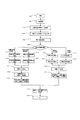
次に、図1及び図4を参照しつつ、実施例1の映像・地図連動システムの作用(映像・地図連動方法)について説明する。図4は、実施例1に係る映像・地図連動システムの作用(映像・地図連動方法)を説明するフローチャートである。
(Function)
Next, referring to FIGS. 1 and 4, the operation of the video / map interlocking system (video / map interlocking method) of the first embodiment will be described. FIG. 4 is a flowchart for explaining the operation (video / map link method) of the video / map link system according to the first embodiment.

ステップS1で本実施例の映像・地図連動システムの動作を開始すると、撮影倍率、撮影方向等について初期状態に設定された撮影条件下で、カメラ31で撮影された映像データは、例えば通信ネットワークを介して映像・地図情報処理サーバー41に送信される。そして、この映像データは、映像・地図情報処理サーバー41の映像入力部9でデジタル信号として受信された後、映像変換(処理)部12で映像データに変換され(ステップS2)、映像・地図同期処理部14に送られる。同時に、この映像データに含まれる撮影対象物について計測された焦点距離f、撮影方向等の撮影情報の元となる計測データが、映像・地図情報処理サーバー41の信号入力部11で受信され、映像・地図同期処理部14内に送られる。映像・地図同期処理部14の視野算出部14aで、視野範囲や、カメラ31の位置から撮影対象物の位置までの平面上における距離L等が算出される。(ステップS3)。算出された視野範囲等は、地図上に表示すべき映像データに関する撮影情報となる。   When the operation of the video / map link system of the present embodiment is started in step S1, video data shot by the camera 31 under the shooting conditions set in the initial state with respect to the shooting magnification, shooting direction, and the like are transmitted through, for example, a communication network. To the video / map information processing server 41. The video data is received as a digital signal by the video input unit 9 of the video / map information processing server 41, and then converted into video data by the video conversion (processing) unit 12 (step S2). It is sent to the processing unit 14. At the same time, the measurement data that is the basis of the shooting information such as the focal length f and the shooting direction measured for the shooting object included in the video data is received by the signal input unit 11 of the video / map information processing server 41, and the video -It is sent into the map synchronization processing unit 14. The visual field calculation unit 14a of the video / map synchronization processing unit 14 calculates the visual field range, the distance L on the plane from the position of the camera 31 to the position of the object to be photographed, and the like. (Step S3). The calculated visual field range or the like becomes photographing information regarding video data to be displayed on the map.

一方、初期状態に設定された撮影倍率についての数値データは、カメラ倍率算出部14bから地図倍率算出部14cへと送られ、撮影倍率に対応した地図倍率を有する地図データが取得される。そして、地図再生処理部14fにおいて、この地図データに、視野算出部14aで算出された映像データに関する撮影情報が図示される(表示される。反映される)。   On the other hand, the numerical data regarding the photographing magnification set in the initial state is sent from the camera magnification calculating section 14b to the map magnification calculating section 14c, and map data having a map magnification corresponding to the photographing magnification is acquired. Then, in the map reproduction processing unit 14f, shooting information related to the video data calculated by the visual field calculation unit 14a is illustrated (displayed and reflected) in the map data.

ステップS4で、この映像データに関する撮影情報(撮影方向、撮影の視野範囲、撮影の中心点、撮影の倍率等)が反映された地図データとカメラ31から映像入力部9及び映像変換部12を介して送られてきた映像データとが、映像・地図同期部14gにおいて同期される。このようにして、地図データと映像データとが連動される。   In step S4, the map data reflecting the shooting information (shooting direction, shooting field-of-view range, shooting center point, shooting magnification, etc.) relating to the video data and the camera 31 via the video input unit 9 and the video conversion unit 12 are reflected. The video data sent in this manner is synchronized in the video / map synchronization unit 14g. In this way, the map data and the video data are linked.

同期された映像データと地図データとは、映像・地図出力部15から利用端末51に出力送信され、利用端末51の表示部20に表示される(ステップS5)。   The synchronized video data and map data are output and transmitted from the video / map output unit 15 to the use terminal 51 and displayed on the display unit 20 of the use terminal 51 (step S5).

ステップS6では、利用端末51から入力する操作の種類が次のように選択される。映像の倍率変更についての操作入力が行われた場合には、この操作入力についての信号は通信ネットワークを介して地図・映像情報処理サーバー41に送信され、倍率変更認識部16を介してこの操作入力量を定量化した操作入力信号が映像・地図同期処理部14に送られる。この操作入力信号を基に、映像・地図同期処理部14のカメラ倍率算出部14bにおいてカメラの倍率変更率が算出される(ステップS7)。カメラ倍率算出部14bは、算出されたカメラの倍率変更率に対応して地図の倍率変更率を算出する(ステップS8)。   In step S6, the type of operation input from the use terminal 51 is selected as follows. When an operation input for changing the magnification of the video is performed, a signal about the operation input is transmitted to the map / video information processing server 41 via the communication network, and this operation input is sent via the magnification change recognition unit 16. An operation input signal whose amount is quantified is sent to the video / map synchronization processing unit 14. Based on this operation input signal, the camera magnification calculator 14b of the video / map synchronization processor 14 calculates the camera magnification change rate (step S7). The camera magnification calculator 14b calculates a map magnification change rate corresponding to the calculated camera magnification change rate (step S8).

ステップS6で、地図の倍率変更についての操作入力が行われた場合には、同様にして、カメラ倍率算出部14bは、地図の倍率変更率を算出する(ステップS9)。さらに、カメラ倍率算出部14bは、算出された地図の倍率変更率に対応してカメラの倍率変更率を算出する(ステップS10)。   If an operation input for changing the map magnification is made in step S6, the camera magnification calculator 14b calculates the map magnification change rate in the same manner (step S9). Further, the camera magnification calculation unit 14b calculates the magnification change rate of the camera corresponding to the calculated map magnification change rate (step S10).

算出されたカメラの倍率変更率は、さらには、実際に映像を撮影するための信号に変換され、信号出力部10からカメラ31に送信される。この映像を撮影するための信号に基づきカメラ31の制御が行われる(ステップS11)。つまり、カメラ31内の信号入力部7で受信された映像を撮影するための信号は制御部5に送られ、この信号に基づいて制御部5が撮影映像部1を制御し、所望の映像が撮影される。倍率変更されて撮影された新たな映像データは、映像出力部6から映像・地図情報処理サーバー41に送信される。この新たな映像データは、映像・地図情報処理サーバー41の映像入力部9で受信され、映像変換部12を経て、映像・地図同期処理部14に送られる。   The calculated camera magnification change rate is further converted into a signal for actually capturing a video and transmitted from the signal output unit 10 to the camera 31. The camera 31 is controlled on the basis of a signal for photographing this video (step S11). In other words, a signal for capturing a video received by the signal input unit 7 in the camera 31 is sent to the control unit 5, and the control unit 5 controls the captured video unit 1 based on this signal so that a desired video is displayed. Taken. New video data shot with the magnification changed is transmitted from the video output unit 6 to the video / map information processing server 41. The new video data is received by the video input unit 9 of the video / map information processing server 41 and sent to the video / map synchronization processing unit 14 via the video conversion unit 12.

映像・地図同期処理部14では、信号入力部11から送られてきた新たな撮影データに含まれる撮影対象物に関する撮影情報となる計測データ(具体的にはカメラ31の焦点計測部2や角度計測部4で計測された数値データ)に基づいて、既に述べた映像・地図連動方法(取得した映像データに関する撮影情報を、映像データと対応して取得した地図データ上に反映させる、つまり、表示・図示する方法)を用いることにより、受信した映像データと地図データとを連動させる。   In the video / map synchronization processing unit 14, measurement data (specifically, the focus measurement unit 2 and the angle measurement of the camera 31) which is shooting information regarding the shooting target included in the new shooting data sent from the signal input unit 11. Based on the numerical data measured by the unit 4, the already described video / map linkage method (shooting information related to the acquired video data is reflected on the map data acquired corresponding to the video data, that is, display / By using the method shown in the figure, the received video data and map data are linked.

具体的には、視野算出部14aは、カメラ31から送られてきた上記撮影情報となる計測データに基づき、カメラ31の位置から撮影対象物32の位置までの平面上における距離Lを算出する(ステップS12)。さらに、視野算出部14aは、算出した距離Lと、カメラ倍率算出部14bで算出された(数値データ化された)カメラの倍率変更率とから、地図上において距離Lと対応する距離l(エル)や、地図上に表示すべき視野の範囲を導き出す(視野の範囲規定する新たな境界線を算出する)(ステップS13)。この距離l(エル)が導き出される(算出される)ことにより、地図(地図データ)上における撮影対象物32’の位置が特定されることとなる。つまり、撮影対象物32’は、地図上において距離l(エル)を有する矢印36の先端に位置するものとして特定される(図3(b)参照)。   Specifically, the visual field calculation unit 14a calculates a distance L on a plane from the position of the camera 31 to the position of the shooting target 32 based on the measurement data that is the shooting information sent from the camera 31 ( Step S12). Further, the field-of-view calculation unit 14a calculates the distance l corresponding to the distance L on the map from the calculated distance L and the magnification change rate of the camera (converted into numerical data) calculated by the camera magnification calculation unit 14b. ) Or a range of field of view to be displayed on the map (a new boundary line defining the range of field of view is calculated) (step S13). By deriving (calculating) this distance l (el), the position of the object 32 'on the map (map data) is specified. That is, the photographing object 32 'is specified as being located at the tip of the arrow 36 having a distance l (el) on the map (see FIG. 3B).

一方、ステップS8又はステップS9でカメラ倍率算出部14bにおいて算出された地図の倍率変更率を基に、地図倍率算出部14cは、地図・映像データ記憶部13から所望の倍率の地図データを取得する(ステップS14)。   On the other hand, based on the map magnification change rate calculated by the camera magnification calculator 14b in step S8 or S9, the map magnification calculator 14c acquires map data of a desired magnification from the map / video data storage unit 13. (Step S14).

次に、地図再生処理部14fは、視野算出部14aで導き出された距離l(エル)、言い換えれば、距離l(エル)により特定された地図データ上における撮影対象物32’の位置を基に、カメラの撮影方向、撮影の視野範囲、撮影の倍率、撮影対象物32’の位置、撮影対象物32’についての情報(例えば、撮影対象物32’の名称、住所、行き方、ホームページアドレス等の情報)等の映像データに関する撮影情報を、地図倍率算出部14cにより取得された地図データに反映させる(表示する。図示する)。このようにして、撮影情報を反映させた地図データが再生される(ステップS15)。そして、映像・地図同期部14gにおいて、上記のようにして新たに倍率変更されて撮影された映像データと撮影情報を反映させた地図データとが同期され(ステップS16)、映像・地図出力部15から出力される(ステップS17)。   Next, the map reproduction processing unit 14f is based on the position of the photographing object 32 ′ on the map data specified by the distance l (el) derived by the visual field calculation unit 14a, in other words, the distance l (el). , The shooting direction of the camera, the shooting field of view, the shooting magnification, the position of the shooting target 32 ′, information about the shooting target 32 ′ (for example, the name, address, direction, homepage address, etc. of the shooting target 32 ′) Shooting information related to video data such as (information) is reflected (displayed) in the map data acquired by the map magnification calculation unit 14c. In this way, the map data reflecting the shooting information is reproduced (step S15). Then, the video / map synchronization unit 14g synchronizes the video data captured with the new magnification change as described above and the map data reflecting the imaging information (step S16), and the video / map output unit 15 (Step S17).

ステップS6で、映像の方向(撮影対象物の方向)変更についての操作入力が行われた場合には、この操作入力に基づく信号が、ネットワーク通信を介して映像・地図情報処理サーバー41に送信され、カメラ方向認識部17により映像データの方向についての操作入力信号に変えられて映像・地図同期処理部14に送られる。   When an operation input for changing the direction of the image (the direction of the object to be imaged) is performed in step S6, a signal based on this operation input is transmitted to the image / map information processing server 41 via network communication. Then, the camera direction recognition unit 17 changes the operation input signal to the direction of the video data and sends it to the video / map synchronization processing unit 14.

ステップS19で、カメラ方向算出部14dは、受け取った映像データの方向についての操作入力信号を基に、カメラ31を実際に動かす(映像を撮影する)ための信号に変換する(カメラ方向を算出する)(ステップS19)。さらに、カメラ方向算出部14dは、カメラ方向の算出に対応して、地図上における撮影対象物の方向変更率、つまり、図2の地図上に示される矢印36の方向についての移動量を算出する(ステップS20)。   In step S19, the camera direction calculation unit 14d converts the camera 31 into a signal for actually moving (capturing the video) based on the operation input signal regarding the direction of the received video data (calculating the camera direction). (Step S19). Furthermore, the camera direction calculation unit 14d calculates the direction change rate of the object to be photographed on the map, that is, the amount of movement in the direction of the arrow 36 shown on the map of FIG. 2 in response to the calculation of the camera direction. (Step S20).

同様にして、ステップS6で、地図上における撮影対象物(撮影)の方向を変更する操作入力が行われた場合には、この操作入力に基づく信号が、映像・地図処理サーバー41に送信された後、地図方向操作(変更)認識部18で地図上における撮影対象物の方向についての操作入力信号に変えられる。この操作入力信号を基に、地図方向算出部14eで、地図上における撮影対象物の(地図についての)方向変更率が算出される(ステップS21)。算出された方向変更率は、カメラ方向算出部14dに送られ、カメラ方向算出部14dにおいて、対応するカメラ方向が算出される(ステップS22)。   Similarly, when an operation input for changing the direction of the object to be imaged (photographing) on the map is performed in step S6, a signal based on this operation input is transmitted to the video / map processing server 41. Thereafter, the map direction operation (change) recognition unit 18 changes the operation input signal to the direction of the object to be photographed on the map. Based on this operation input signal, the map direction calculation unit 14e calculates the direction change rate (with respect to the map) of the object to be photographed on the map (step S21). The calculated direction change rate is sent to the camera direction calculation unit 14d, and the camera direction calculation unit 14d calculates the corresponding camera direction (step S22).

算出されたカメラ方向についての信号、つまり、カメラ31を実際に動かすための信号は、信号出力部10を介してカメラ31に送信され、この送信された信号に基づいてカメラ制御が行われる(ステップS23)。そして、所望の方向について映像が撮影される。   A signal for the calculated camera direction, that is, a signal for actually moving the camera 31, is transmitted to the camera 31 via the signal output unit 10, and camera control is performed based on the transmitted signal (step). S23). Then, a video is taken in a desired direction.

一方、ステップS20又はステップS21において算出された地図上における撮影対象物についての(地図についての)方向変更率を基に、視野算出部14aにおいて、方向変更された新たな視野範囲が算出される。つまり、地図上に図示されるべき新たな撮影対象物の方向についての矢印と視野範囲とが導き出され、方向変更された後の地図上における撮影対象物の位置が特定される。そして、特定された撮影対象物の位置を基に、この撮影対象物についての情報や導き出された視野範囲等の撮影対象物を含む映像データに関する撮影情報は、地図再生処理部14fにおいて、地図データに反映される(表示、図示される)(ステップS24)。   On the other hand, based on the direction change rate (with respect to the map) for the object to be photographed on the map calculated in step S20 or step S21, the visual field calculation unit 14a calculates a new visual field range whose direction has been changed. That is, an arrow and a field-of-view range regarding the direction of a new photographing object to be illustrated on the map are derived, and the position of the photographing object on the map after the direction is changed is specified. Then, on the basis of the position of the specified shooting object, shooting information on the shooting data such as information about the shooting object and the shooting object such as the derived visual field range is transmitted to the map data in the map reproduction processing unit 14f. Is reflected (displayed and illustrated) (step S24).

カメラ31から送られてきた所望の方向についての映像データと、地図再生処理部14fで撮影情報が反映された地図データとは、映像・地図同期部14gで同期され(ステップS16)、映像・地図出力部15を介して出力される(ステップS17)。上記のようにして、所望の方向について撮影される映像データと地図データとが連動される。   The video data about the desired direction sent from the camera 31 and the map data reflecting the shooting information by the map reproduction processing unit 14f are synchronized by the video / map synchronization unit 14g (step S16), and the video / map is obtained. The data is output via the output unit 15 (step S17). As described above, the video data photographed in a desired direction and the map data are linked.

出力された映像データと地図データとは、映像・地図出力部15からネットワーク通信を介して利用端末51に送信され、利用端末51の表示部20に表示される。なお、このとき、少なくとも撮影対象物32’についての情報を、利用端末51に設けられるスピーカ(図示せず)を介して音声により出力する(伝達する)ことにしてもよい。   The output video data and map data are transmitted from the video / map output unit 15 to the use terminal 51 via network communication and displayed on the display unit 20 of the use terminal 51. At this time, at least information about the imaging target 32 ′ may be output (transmitted) by voice via a speaker (not shown) provided in the use terminal 51.

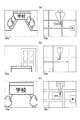
図5、図6は、上述した本発明に係る映像・地図連動システムにより得られた映像データと地図データとが、それぞれ利用端末51の映像表示部20aと地図表示部20bとに表示された例である。   5 and 6 are examples in which video data and map data obtained by the video / map linkage system according to the present invention described above are displayed on the video display unit 20a and the map display unit 20b of the use terminal 51, respectively. It is.

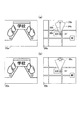
図5は、撮影の倍率(撮影の視野範囲、視野の範囲)を変更して表示された映像及び地図の例である。図5(a)では、初期状態に設定された(基本の)撮影の倍率(視野の範囲)で撮影された映像と、この映像に連動した地図とが示される。図5(b)では、図5(a)で撮影された映像について遠方を拡大したとき(望遠時)の映像とそれに連動した地図とが示される。図5(c)では、図5(a)で撮影された映像について近方を拡大したとき(近方拡大時)の映像とそれに連動した地図とが示される。   FIG. 5 is an example of an image and a map displayed by changing the shooting magnification (shooting field range, field range). In FIG. 5A, an image captured at the (basic) magnification (field of view range) set in the initial state and a map linked to the image are shown. In FIG. 5B, an image when the distant portion of the image taken in FIG. 5A is enlarged (at the time of telephoto) and a map linked to the image are shown. FIG. 5 (c) shows a video when the vicinity of the video imaged in FIG. 5 (a) is magnified (at the time of near magnification) and a map associated therewith.

図6は、撮影された映像についての倍率、視野の範囲等の撮影情報を地図上に反映させる表示形態の例を示す。図6(a)では、映像表示部20aで示される映像に対応して、図3で既に説明したように、地図上のカメラ31’の位置を基点として視野の範囲の境界線33b、34bと円弧35bとで囲まれた視野の範囲、及び、カメラ31’の位置から撮影の対象物の位置までの方向と距離とを表す矢印36bが地図表示部20bに示されている。図6(b)には、撮影された映像(撮影対象となる映像)の中心点32cが例えば星印で地図表示部20bに示されている。撮影の中心点、つまり、撮影される映像の焦点となる対象物は、地図上においてこの中心点32cに位置する。   FIG. 6 shows an example of a display form in which shooting information such as a magnification and a field of view for a shot video is reflected on a map. In FIG. 6A, corresponding to the video displayed on the video display unit 20a, as already described in FIG. 3, the boundary lines 33b and 34b of the field of view range with the position of the camera 31 ′ on the map as a base point A field of view that is surrounded by the arc 35b, and an arrow 36b that indicates the direction and distance from the position of the camera 31 'to the position of the object to be photographed are shown on the map display unit 20b. In FIG. 6B, the center point 32c of the photographed video (video to be photographed) is shown on the map display unit 20b with, for example, stars. The center point of shooting, that is, the object that is the focal point of the shot image is located at this center point 32c on the map.

上記のように、カメラで撮影された映像と地図とを連動させる。つまり、カメラで撮影された映像に対応する地図が表示されると共に、カメラの撮影の方向、撮影の視野範囲、撮影の倍率、撮影対象物の位置(撮影の中心点)といった映像データに関する撮影情報を地図上に反映させる(表示、図示する)。したがって、このような地図及び撮影された映像を見比べることにより、画面52を見ている者は、映像中の撮影対象物は何か(どの対象物を見ているのか)、また、どの方向を見ているのか、さらにはどの撮影範囲を見ているのか等を容易に理解することができる。よって、撮影の対象物を容易に特定することができ、また、撮影された映像についての情報を把握することができる。   As described above, the image captured by the camera and the map are linked. In other words, a map corresponding to the video shot by the camera is displayed, and shooting information relating to video data such as the shooting direction of the camera, the shooting field of view, the shooting magnification, and the position of the shooting target (the center point of shooting) Is reflected on the map (displayed, illustrated). Therefore, by comparing such a map and the captured video, the person who is viewing the screen 52 is what is the shooting target in the video (which target is being viewed) and in what direction. You can easily understand what you are looking at, and what shooting range you are looking at. Therefore, it is possible to easily identify an object to be photographed, and to grasp information about the photographed video.

さらに、映像データに関する撮影情報として、撮影対象物についての情報(例えば、撮影対象物の名称、住所、行き方、ホームページアドレス等の情報)も上記映像データに関する撮影情報と共に、表示する及び/又は音声により出力することにより、一層撮影対象物の特定や情報把握が容易となり、利便性を高めることができる。   Further, as shooting information related to the video data, information about the shooting target (for example, information such as the name, address, way to go, and home page address of the shooting target) is displayed together with the shooting information related to the video data and / or by voice. By outputting, it becomes easier to specify the object to be photographed and grasp information, and the convenience can be improved.

図7は、本発明の実施例2に係る映像・地図連動システムの全体構成を示す図である。実施例2の映像・地図連動システムは、実施例1の映像・地図連動システムに類似し、同一の構成部分には、同一の参照符号を付して説明を省略する。   FIG. 7 is a diagram illustrating the overall configuration of the video / map linkage system according to the second embodiment of the present invention. The video / map interlocking system of the second embodiment is similar to the video / map interlocking system of the first embodiment, and the same components are denoted by the same reference numerals and description thereof is omitted.

実施例2が実施例1と異なるのは、映像・地図連動システムを構成するカメラとして、360度全方位において映像データの取得を可能とする全方位撮影型のカメラ131が用いられていることである。したがって、実施例2の映像・地図連動システムでは、全方位撮影型のカメラ131に対応した構成を有すると共にこのカメラ131に対応した処理を行う。以下に、実施例1と異なる点について、実施例2の映像・地図連動システムの構成を簡単に説明する。   The second embodiment is different from the first embodiment in that an omnidirectional camera 131 that enables acquisition of video data in 360-degree omnidirectional is used as a camera constituting the video / map linkage system. is there. Therefore, the video / map linkage system according to the second embodiment has a configuration corresponding to the omnidirectional camera 131 and performs processing corresponding to the camera 131. The configuration of the video / map interlocking system of the second embodiment will be briefly described below with respect to differences from the first embodiment.

実施例2の映像・地図連動システムは、実施例1と同様の利用端末51の他、全方位撮影型のカメラ131と、カメラ131に対応した処理を行う映像・地図情報処理サーバー141とを備える。全方位撮影型のカメラ131では、予め定められた倍率の下で、全方位、つまり360度に渡る全ての方向についての映像データが撮影される。したがって、カメラ131の位置から撮影対象物の位置までの距離Lは、例えば予め算出されている。撮影された全方位についての映像データは、映像・地図情報処理サーバー141に通信ネットワークを介して送信される。   The video / map linkage system of the second embodiment includes an omnidirectional camera 131 and a video / map information processing server 141 that performs processing corresponding to the camera 131 in addition to the use terminal 51 similar to that of the first embodiment. . The omnidirectional camera 131 shoots image data in all directions, that is, all directions over 360 degrees under a predetermined magnification. Therefore, the distance L from the position of the camera 131 to the position of the object to be photographed is calculated in advance, for example. Video data for all directions taken is transmitted to the video / map information processing server 141 via a communication network.

映像・地図情報処理サーバー141内には、実施例1のカメラ方向変更認識部17(図1参照)に代えて、映像方向変更認識部117が設けられている。また、映像・地図情報処理サーバー141は、所望の映像データと地図データとを連動させる映像・地図同期処理部114を有する。映像・地図同期処理部114は、映像方向算出部114dと、映像倍率算出部114bと、地図内表示視野算出部114aと、映像データ処理部114hと、を含む。   In the video / map information processing server 141, a video direction change recognition unit 117 is provided instead of the camera direction change recognition unit 17 (see FIG. 1) of the first embodiment. The video / map information processing server 141 includes a video / map synchronization processing unit 114 that links desired video data and map data. The video / map synchronization processing unit 114 includes a video direction calculation unit 114d, a video magnification calculation unit 114b, an intra-map display visual field calculation unit 114a, and a video data processing unit 114h.

映像方向算出部114dは、映像方向変更認識部117から送られてくる映像の所望の方向についての操作入力信号に基づき、取得すべき映像データの方向についての信号(映像の方向データ)を算出する。映像倍率算出部114bは、倍率変更認識部16から送られてくる所望の映像又は地図の倍率についての操作入力信号を基づき、映像及び地図それぞれの倍率変更率を算出する。地図内表示視野算出部114aは、映像倍率算出部114bで算出される倍率変更率と、地図方向算出部14eで算出される地図方向データ、つまり、地図上に示される矢印36の方向(図2参照)についての移動量を基に、地図内に表示すべき視野の範囲を導く。この視野の範囲等の撮影情報は、実施例1と同様にして、地図倍率算出部14cにより地図・映像位置データ記憶部13から取得された所望の倍率の地図上に、地図再生処理部14fにおいて図示される(反映される)。   The video direction calculation unit 114d calculates a signal (video direction data) about the direction of the video data to be acquired based on the operation input signal about the desired direction of the video sent from the video direction change recognition unit 117. . The video magnification calculation unit 114b calculates the magnification change rate for each of the video and the map based on the operation input signal for the desired video or map magnification sent from the magnification change recognition unit 16. The intra-map display visual field calculation unit 114a and the magnification change rate calculated by the video magnification calculation unit 114b and the map direction data calculated by the map direction calculation unit 14e, that is, the direction of the arrow 36 shown on the map (FIG. 2). The range of the field of view to be displayed in the map is derived based on the movement amount for the reference). The photographing information such as the field of view is the same as in the first embodiment, and the map reproduction processing unit 14f places the map magnification processing unit 14c on the map with the desired magnification acquired from the map / video position data storage unit 13 by the map reproduction processing unit 14f. Illustrated (reflected).

映像データ処理部114hは、映像方向算出部114dで算出された映像方向データ、及び映像倍率算出部114bで算出された倍率変更率を基に、カメラ131から送られてきた全方位についての映像データのうち所望の方向の映像データを取得すると共に、所望の倍率にする処理を行う。   The video data processing unit 114h sends video data for all directions sent from the camera 131 based on the video direction data calculated by the video direction calculation unit 114d and the magnification change rate calculated by the video magnification calculation unit 114b. Among these, the video data in a desired direction is acquired, and a process for obtaining a desired magnification is performed.

このようにして得られた所望の映像データと、この映像データに関する撮影情報が反映された地図データとは、実施例1と同様に、映像・地図同期部14gで同期され、映像・地図出力部15を介して出力され、利用端末51の表示部20に表示される。本実施例においても、撮影対象物についての情報を含む映像データに関する撮影情報を、利用端末51において音声出力することができる。その他、本実施例においても、実施例1と同様の効果が得られる。   The desired video data obtained in this way and the map data reflecting the shooting information relating to this video data are synchronized by the video / map synchronization unit 14g as in the first embodiment, and the video / map output unit. 15 and displayed on the display unit 20 of the use terminal 51. Also in the present embodiment, shooting information related to video data including information about the shooting target can be output as audio at the use terminal 51. In addition, also in the present embodiment, the same effects as in the first embodiment can be obtained.

(作用)
次に、図7、図8を参照しつつ、上述した実施例2に係る映像・地図連動システムの作用(映像・地図連動方法)について説明する。図8は、実施例2に係る映像・地図連動システムの作用(映像・地図連動方法)を説明するフローチャートである。
(Function)
Next, referring to FIGS. 7 and 8, the operation of the video / map interlocking system (video / map interlocking method) according to the second embodiment will be described. FIG. 8 is a flowchart for explaining the operation of the video / map link system (video / map link method) according to the second embodiment.

ステップS101で、実施例2の映像・地図連動システムの動作を開始すると、予め定められた撮影倍率の下で、カメラ131で撮影された全方位についての映像データは、映像・地図情報処理サーバー141に送信される。   When the operation of the video / map linkage system of the second embodiment is started in step S101, the video / map information processing server 141 stores video data for all directions shot by the camera 131 under a predetermined shooting magnification. Sent to.

この全方位についての映像データは、映像・地図情報処理サーバー141の映像入力部9で、デジタル信号として受信された後、映像変換部12で映像データに変換され(ステップS102)、映像・地図同期処理部114内に送られる。   The video data for all directions is received as a digital signal by the video input unit 9 of the video / map information processing server 141, and then converted into video data by the video conversion unit 12 (step S102). It is sent into the processing unit 114.

映像・地図同期処理部114では、映像方向算出部114dは、初期状態において取得すべき映像の方向データ、つまり、全方位の映像データのうちどの方向の映像データを初期状態において取得するかについてのデータを算出している。この映像の方向データに基づいて、映像データ処理部114hは、予め定められた倍率を有する全方位についての映像データから初期状態における方向の映像データを取得する(ステップS103)。   In the video / map synchronization processing unit 114, the video direction calculation unit 114d determines which direction of the video data to be acquired in the initial state, that is, which direction of the video data is to be acquired in the initial state. Data is calculated. Based on the video direction data, the video data processing unit 114h acquires video data in the initial state from video data for all directions having a predetermined magnification (step S103).

さらに、映像方向算出部114dでは、算出された映像の方向データに対応して地図の方向データを算出している。この地図の方向データは地図方向算出部14eを介して地図内表示視野算出部114aに送られる。地図内表示視野算出部114aにおいて、カメラ131の位置から対象物の位置までの距離Lに対応する地図上での距離l(エル)(この距離lにより、地図上における撮影対象物の位置が特定される)、地図上に表示すべき視野の範囲等の撮影データに関する撮影情報が算出される。算出された撮影データに関する撮影情報は、地図再生処理部14fに送られる。   Further, the video direction calculation unit 114d calculates map direction data corresponding to the calculated video direction data. The map direction data is sent to the in-map display visual field calculation unit 114a via the map direction calculation unit 14e. In the map display visual field calculation unit 114a, the distance l (el) on the map corresponding to the distance L from the position of the camera 131 to the position of the object (the distance l identifies the position of the object to be photographed on the map). Shooting information relating to shooting data such as the range of field of view to be displayed on the map is calculated. The shooting information related to the calculated shooting data is sent to the map reproduction processing unit 14f.

一方、予め定められた撮影倍率についての数値データは、映像倍率算出部114bから地図倍率算出部14cへと送られ、地図倍率算出部14cで撮影倍率に対応した地図倍率を有する地図データが地図・映像位置データ記憶部13から取得される。取得された地図データは、地図再生処理部14fに送られ、地図再生処理部14fにおいて、この地図データに、地図内表示視野算出部114aで算出された撮影データに関する撮影情報が反映される(表示、図示される)。   On the other hand, numerical data on the predetermined shooting magnification is sent from the video magnification calculator 114b to the map magnification calculator 14c, and the map magnification calculator 14c generates map data having a map magnification corresponding to the shooting magnification. Obtained from the video position data storage unit 13. The acquired map data is sent to the map reproduction processing unit 14f, and the map reproduction processing unit 14f reflects imaging information related to the imaging data calculated by the in-map display visual field calculation unit 114a (display). ).

ステップS104で、この撮影データに関する撮影情報が反映された地図データと、ステップS103で取得された映像データとは、映像・地図同期部14gで同期される。同期された映像データと地図データとは、映像・地図出力部15を介して利用端末51に送信され、表示部20に表示される(ステップS105)。   In step S104, the map data reflecting the shooting information relating to the shooting data and the video data acquired in step S103 are synchronized by the video / map synchronization unit 14g. The synchronized video data and map data are transmitted to the user terminal 51 via the video / map output unit 15 and displayed on the display unit 20 (step S105).

ステップS106では、利用端末51から入力する操作の種類が次のように選択される。映像の倍率変更についての新たな操作入力が行われた場合には、この操作入力についての信号は通信ネットワークを介して地図・映像情報処理サーバー141に送信され、倍率変更認識部16を介してこの操作入力量を定量化した操作入力信号が映像・地図同期処理部114に送られる。この操作入力信号を基に、映像・地図同期処理部114の映像倍率算出部114bにおいて映像の倍率変更率が算出される(ステップS107)。映像倍率算出部114bは、算出された映像の倍率変更率に対応して地図の倍率変更率を算出する(ステップS108)。算出された地図の倍率変更率は、地図倍率算出部14cに送られる。   In step S106, the type of operation input from the use terminal 51 is selected as follows. When a new operation input for video magnification change is performed, a signal for this operation input is transmitted to the map / video information processing server 141 via the communication network, and this signal is input via the magnification change recognition unit 16. An operation input signal obtained by quantifying the operation input amount is sent to the video / map synchronization processing unit 114. Based on the operation input signal, the video magnification calculation unit 114b of the video / map synchronization processing unit 114 calculates the video magnification change rate (step S107). The video magnification calculator 114b calculates a map magnification change rate corresponding to the calculated video magnification change rate (step S108). The calculated map magnification change rate is sent to the map magnification calculator 14c.

ステップS106で、地図の倍率変更についての新たな操作入力が行われた場合には、同様にして、映像倍率算出部114bは、地図の倍率変更率を算出する(ステップS109)。さらに、映像倍率算出部114bは、算出された地図の倍率変更率に対応して映像の倍率変更率を算出する(ステップS110)。算出された映像の倍率変更率は、映像データ処理部114hに送られる。   When a new operation input for changing the map magnification is made in step S106, the video magnification calculator 114b similarly calculates the map magnification change rate (step S109). Further, the video magnification calculator 114b calculates a video magnification change rate corresponding to the calculated map magnification change rate (step S110). The calculated video magnification change rate is sent to the video data processing unit 114h.

映像データ処理部114hでは、全方位の映像データから初期状態の倍率及び方向で取得されている映像データについて、ステップS110で新たに算出された倍率変更率に基づき、拡大又は縮小の倍率変更についての処理が行われ、新たな映像データが生成される(ステップS111)。   In the video data processing unit 114h, with respect to video data acquired from the omnidirectional video data at the initial magnification and direction, the enlargement or reduction magnification change is performed based on the magnification change rate newly calculated in step S110. Processing is performed and new video data is generated (step S111).

一方、ステップS108又はステップS109で映像倍率算出部114bにおいて算出された地図の倍率変更率を基に、地図倍率算出部14cは、地図・映像データ記憶部13から所望の倍率の地図データを取得する(ステップS112)取得された所望の倍率の地図データは、地図再生処理部14fに送られる。   On the other hand, the map magnification calculation unit 14c acquires map data of a desired magnification from the map / video data storage unit 13 based on the map magnification change rate calculated by the video magnification calculation unit 114b in step S108 or step S109. (Step S112) The acquired map data of the desired magnification is sent to the map reproduction processing unit 14f.

次に、地図再生処理部14fは、地図倍率算出部14cで取得された地図データに、地図内視野算出部114aで算出された視野の範囲等の映像データに関する撮影情報を反映させる(表示、図示する)。このようにして、映像データに関する撮影情報を反映させた地図データが再生される(ステップS113)。上記のように、新たに倍率変更された映像データと、この映像データについての撮影情報を反映させた地図データとは、映像・地図同期部14gで同期され(ステップS114)、映像・地図出力部15から出力される(ステップS115)。   Next, the map reproduction processing unit 14f reflects the shooting information regarding the video data such as the range of the visual field calculated by the intra-map visual field calculation unit 114a in the map data acquired by the map magnification calculation unit 14c (display, illustrated). To do). In this way, the map data reflecting the shooting information relating to the video data is reproduced (step S113). As described above, the video data whose magnification has been newly changed and the map data reflecting the shooting information on the video data are synchronized by the video / map synchronization unit 14g (step S114), and the video / map output unit 15 (step S115).

ステップS106で、映像の方向変更についての新たな操作入力が行われた場合には、この操作入力に基づく信号が、ネットワーク通信を介して映像・地図情報処理サーバー41に送信され、映像方向変更認識部117により映像データの方向についての操作入力信号に変えられて映像・地図同期処理部114に送られる。   When a new operation input for changing the direction of the video is performed in step S106, a signal based on this operation input is transmitted to the video / map information processing server 41 via the network communication to recognize the video direction change. It is changed to an operation input signal for the direction of the video data by the unit 117 and sent to the video / map synchronization processing unit 114.

ステップS116で、映像方向算出部114dは、受け取った映像データの方向についての操作入力信号を基に、映像の方向データ、つまり、全方位の映像データのうちどの方向の映像データを取得するかについてのデータに変換する。(映像方向を算出する)(ステップS116)。この映像の方向データに対応して、地図方向算出部14eは、地図の方向データ、つまり、地図上に示される矢印36の方向(図2参照)についての移動量を算出する(地図方向を算出する)(ステップS117)。   In step S116, the video direction calculation unit 114d determines which direction of the video direction data, that is, the video data in all directions is to be acquired based on the operation input signal regarding the direction of the received video data. Convert to data. (Image direction is calculated) (step S116). Corresponding to this video direction data, the map direction calculation unit 14e calculates the amount of movement in the direction data of the map, that is, the direction of the arrow 36 shown on the map (see FIG. 2) (calculates the map direction). (Step S117).

同様にして、ステップS106で、地図の方向変更についての新たな操作入力が行われた場合には、この操作入力に基づく信号が、映像・地図処理サーバー141に送信された後、地図方向変更認識部18で地図の方向についての操作入力信号に変えられ、この操作入力信号を基に、地図方向算出部14eで地図の方向データが算出される(ステップS118)。そして、この地図の方向データに対応して、映像方向算出部114dは、映像の方向データを算出する(ステップS119)。算出された映像の方向データは、映像データ処理部114hに送られる。   Similarly, when a new operation input for changing the direction of the map is performed in step S106, a signal based on this operation input is transmitted to the video / map processing server 141, and then the map direction change is recognized. The unit 18 changes the operation input signal for the map direction, and the map direction calculation unit 14e calculates the map direction data based on the operation input signal (step S118). Then, in response to the map direction data, the video direction calculation unit 114d calculates video direction data (step S119). The calculated video direction data is sent to the video data processing unit 114h.

算出された映像の方向データに基づき、映像データ処理部114hでは、予め定められた倍率を有する全方位についての映像データから所望の方向についての映像データを取得する。こうして、新たな映像データが生成される(ステップS120)。   Based on the calculated video direction data, the video data processing unit 114h acquires video data for a desired direction from video data for all directions having a predetermined magnification. Thus, new video data is generated (step S120).

一方、ステップS117又はステップS118において算出された地図の方向データは、地図内表示視野算出部114aに送られ、地図内視野算出部114aにおいて、方向変更された視野範囲が算出される。つまり、地図上に図示されるべき新たな方向についての矢印と視野の範囲とが導き出される。そして、導き出された視野範囲等についての映像データに関する撮影情報は、地図再生処理部14fに送られ、地図再生処理部14fにおいて、地図データに反映される(図示される)(ステップS121)。   On the other hand, the map direction data calculated in step S117 or step S118 is sent to the intra-map display visual field calculation unit 114a, and the intra-map visual field calculation unit 114a calculates the visual field range whose direction has been changed. That is, an arrow and a field of view for a new direction to be illustrated on the map are derived. Then, the shooting information related to the video data regarding the derived visual field range or the like is sent to the map reproduction processing unit 14f, and is reflected in the map data (illustrated) in the map reproduction processing unit 14f (step S121).

ステップ120で生成された映像データと、ステップ121でこの映像データに関する撮影情報が反映された地図データとは、映像・地図同期部14gで同期され(ステップS114)、映像・地図出力部15を介して出力される(ステップS115)。上記のようにして、所望の方向についての映像データと地図データとが連動される。   The video data generated in step 120 and the map data reflecting the shooting information related to the video data in step 121 are synchronized by the video / map synchronization unit 14g (step S114), and are transmitted via the video / map output unit 15. Are output (step S115). As described above, video data and map data for a desired direction are linked.

出力された映像データと地図データとは、映像・地図出力部15からネットワーク通信を介して利用端末51に送信され、利用端末51の表示部20に表示される。本実施例においても、実施例1と同様に、少なくとも撮影対象物についての情報を利用端末51のスピーカから音声により出力(伝達)することにしてもよい。   The output video data and map data are transmitted from the video / map output unit 15 to the use terminal 51 via network communication and displayed on the display unit 20 of the use terminal 51. Also in the present embodiment, as in the first embodiment, at least information about the object to be photographed may be output (transmitted) from the speaker of the use terminal 51 by voice.

図9(a)は、実施例2の映像・地図連動システムにより全方位についての映像から所望の方向の映像を取得する様子を示す。所望の方向について取得された映像は、利用端末51の映像表示部20aに表示される(映像表示部20aについては図2参照)。また、図9(b)は、図9(a)で取得された映像(映像データ)に連動して利用端末51の地図表示部20bに表示される地図を示す。   FIG. 9A shows a state in which an image in a desired direction is acquired from an image in all directions by the image / map linkage system according to the second embodiment. The video acquired in the desired direction is displayed on the video display unit 20a of the user terminal 51 (see FIG. 2 for the video display unit 20a). FIG. 9B shows a map displayed on the map display unit 20b of the usage terminal 51 in conjunction with the video (video data) acquired in FIG. 9A.

図9(a)で取得される映像の端の点A、Bはそれぞれ、図9(b)で地図上に表示される視野範囲137’の両端を表す点A、Bに対応している。なお、地図上の矢印136は、地図上におけるカメラ131’の位置からの撮影の方向(撮影対象となる中心方向)を示している。以上説明したように、本実施例においても、実施例1と同様の効果が得られる。   The end points A and B of the video acquired in FIG. 9A correspond to the points A and B representing both ends of the visual field range 137 ′ displayed on the map in FIG. 9B, respectively. Note that an arrow 136 on the map indicates a shooting direction from the position of the camera 131 ′ on the map (a central direction to be shot). As described above, also in this embodiment, the same effect as that of Embodiment 1 can be obtained.

なお、上記各実施例、特に実施例1では、映像・地図連動方法として、カメラ31の位置データからカメラ31で撮影される撮影対象物までの平面上(水平面上)における距離を、カメラ31に基づいて算出し、地図データ上における撮影対象物の位置を特定する方法を用いた。しかし、上記映像・地図連動方法には限られず、他の映像・地図連動方法として、地図・映像位置データ記憶部13に予め対応づけて記憶させておいた撮影画面上における撮影対象物の位置データを基にして、地図データ上における撮影対象物の位置を特定する方法を用いてもよい。   In each of the above-described embodiments, particularly in Embodiment 1, as a video / map linkage method, the distance on the plane (on the horizontal plane) from the position data of the camera 31 to the object to be photographed by the camera 31 is set to the camera 31. Based on this, a method of specifying the position of the photographing object on the map data was used. However, the video / map linkage method is not limited to this, and as another video / map linkage method, the position data of the shooting object on the shooting screen stored in advance in the map / video position data storage unit 13 is stored. Based on the above, a method of specifying the position of the photographing object on the map data may be used.

以上、本発明に係る映像・地図連動システム及びその連動方法の最良の形態を実施例に基づいて説明したが、本発明は特にこのような実施例に限定されることなく、特許請求の範囲記載の技術的事項の範囲内でいろいろな実施例があることはいうまでもない。   As described above, the best mode of the video / map link system and the link method according to the present invention has been described based on the embodiments. However, the present invention is not particularly limited to such embodiments, and is described in the claims. It goes without saying that there are various embodiments within the scope of the technical matters.

本発明の活用例として、インターネットを通じてのニュースや音楽、買い物・観光等の情報を映像で配信するシステムとしての利用、さらには、防犯や災害対策等のために、監視する目的で監視対象となる映像をインターネットを通じて配信するシステムとしての利用が挙げられる。   As an example of use of the present invention, it is used as a system for distributing information such as news, music, shopping / tourism, etc. via video on the Internet, and for monitoring purposes for crime prevention and disaster countermeasures. It can be used as a system for distributing video over the Internet.

本発明の実施例1に係る映像・地図連動システムの全体構成を示すブロック図である。It is a block diagram which shows the whole structure of the image | video / map interlocking system which concerns on Example 1 of this invention. 利用端末の画面の一例を具体的に示した図である。It is the figure which showed an example of the screen of a utilization terminal concretely. 図3(a)は、視野算出部において、カメラの位置から映像の焦点Fとなる対象物(撮影対象とされる映像)の位置までの地上における距離Lを算出する原理を示す図であり、図3(b)は、撮影された映像データと連動して地図データが表示された地図表示部を示す図であり、図3(c)は、新たに規定される視野の境界線及び視野の境界線が成す角度α’が表示される模式的な図を示す。FIG. 3A is a diagram showing the principle of calculating the distance L on the ground from the position of the camera to the position of the target object (video to be captured) from the position of the camera in the visual field calculation unit. FIG. 3B is a diagram showing a map display unit on which map data is displayed in conjunction with the captured video data, and FIG. 3C shows the boundary lines and field of view defined newly. A schematic diagram in which an angle α ′ formed by a boundary line is displayed is shown. 実施例1に係る映像・地図連動システムの操作を説明するフローチャートである。6 is a flowchart illustrating an operation of the video / map linkage system according to the first embodiment. 撮影の倍率(視野の範囲)を変更して表示された映像及び地図の例である。It is an example of the image | video and map displayed by changing the magnification (field of view range) of imaging | photography. 撮影された映像についての倍率、視野の範囲等の撮影情報を地図上に反映させる表示形態の例を示す。The example of the display form which reflects imaging | photography information, such as a magnification about the image | photographed image | video, the range of a visual field, on a map is shown. 本発明の実施例2に係る映像・地図連動システムの全体構成を示すブロック図である。It is a block diagram which shows the whole structure of the image | video / map interlocking system which concerns on Example 2 of this invention. 実施例2に係る映像・地図連動システムの作用を説明するフローチャートである。12 is a flowchart illustrating the operation of the video / map linkage system according to the second embodiment. 図9(a)は、実施例2の映像・地図連動システムにより全方位についての映像から所望の方向の映像を取得する様子を示す図であり、図9(b)は、図9(a)で取得された映像(映像データ)に連動して利用端末の地図表示部に表示される地図を示す図である。FIG. 9A is a diagram illustrating a state in which a video in a desired direction is acquired from a video in all directions by the video / map linkage system according to the second embodiment, and FIG. It is a figure which shows the map displayed on the map display part of a utilization terminal in response to the image | video (video data) acquired by (1).

符号の説明Explanation of symbols

1 映像撮影部
2 焦点計測部
3 方向計測部
4 角度計測部
5 制御部
6 映像出力部
7、11 信号入力部
8、10 信号出力部
9 映像入力部
12 映像変換(処理)部
13地図・映像位置データ記憶部
14、114 映像・地図同期処理部
14a 視野算出部
14b カメラ倍率算出部
14c 地図倍率算出部
14d カメラ方向算出部
14e 地図方向算出部
14f 地図再生処理部
14g 映像・地図同期部
15 映像・地図出力部
16 倍率変更認識部
17 カメラ方向変更認識部
18 地図方向操作(変更)認識部
19 入力部
19a、19b、19c、19d 操作入力ボタン
20 表示部
20a 映像表示部
20b 地図表示部
21 操作認識部
31、31’、131、131’ カメラ
32、32’ 撮影対象物
33、34 境界線
35 円弧
36、136 矢印
37’137’ 視野範囲
41、141 映像・地図情報処理サーバー
51 利用端末
52 画面
114a 地図内視野算出部
114b 映像倍率算出部
114d 映像方向算出部
114h 映像データ処理部
DESCRIPTION OF SYMBOLS 1 Image | video imaging | photography part 2 Focus measurement part 3 Direction measurement part 4 Angle measurement part 5 Control part 6 Image | video output part 7,11 Signal input part 8,10 Signal output part 9 Image | video input part 12 Image | video conversion (processing) part 13 Map and image | video Position data storage unit 14, 114 Video / map synchronization processing unit 14a Field of view calculation unit 14b Camera magnification calculation unit 14c Map magnification calculation unit 14d Camera direction calculation unit 14e Map direction calculation unit 14f Map reproduction processing unit 14g Video / map synchronization unit 15 video Map output unit 16 Magnification change recognition unit 17 Camera direction change recognition unit 18 Map direction operation (change) recognition unit 19 Input unit 19a, 19b, 19c, 19d Operation input buttons 20 Display unit 20a Video display unit 20b Map display unit 21 Operation Recognition unit 31, 31 ', 131, 131' Camera 32, 32 'Object to be photographed 33, 34 Border 35 Arc 6,136 arrow 37'137 'field of view 41, 141 video and map information processing server 51 using terminal 52 screen 114a within map field calculating unit 114b image magnification calculator 114d image direction calculation unit 114h video data processing unit

Claims (7)

一つ又は複数の利用端末と、遠隔地に設けられた少なくとも1つのカメラと、前記利用端末及び前記カメラに通信ネットワークを介して接続される映像・地図情報処理サーバーと、を備えた映像・地図連動システムであって、
前記映像・地図情報処理サーバーは、操作認識部と、映像・地図同期処理部と、地図・映像位置データ記憶部と、を含んでおり、
前記操作認識部は、前記利用端末からの入力に基づき、映像又は地図についての操作入力信号を前記映像・地図同期処理部に送り、
前記地図・映像位置データ記憶部は、地図データと、該地図データに対応させて、少なくとも前記カメラの位置データを記憶し、
前記映像・地図同期処理部は、前記映像又は地図についての操作入力信号に基づき、前記カメラで撮影される撮影対象物を含む映像データを取得すると共に、前記地図・映像位置データ記憶部から前記映像データに対応する地図データを取得し、前記撮影対象物を含む前記映像データに関する撮影情報を前記地図データ上に反映させることを特徴とする映像・地図連動システム。
Video / map comprising one or a plurality of usage terminals, at least one camera provided at a remote location, and a video / map information processing server connected to the usage terminals and the camera via a communication network An interlocking system,
The video / map information processing server includes an operation recognition unit, a video / map synchronization processing unit, and a map / video position data storage unit,
The operation recognition unit sends an operation input signal for a video or a map to the video / map synchronization processing unit based on an input from the user terminal,
The map / video position data storage unit stores map data and at least position data of the camera in association with the map data,
The video / map synchronization processing unit acquires video data including a photographing object photographed by the camera based on an operation input signal for the video or map, and the video / map synchronization processing unit from the map / video position data storage unit. A video / map interlocking system characterized in that map data corresponding to data is acquired and shooting information relating to the video data including the shooting target is reflected on the map data.
前記映像・地図同期処理部は、前記カメラの位置から前記カメラで撮影される撮影対象物の位置までの平面上における距離を算出して、前記地図データ上における前記撮影対象物の位置を特定することにより、前記撮影対象物を含む前記映像データに関する撮影情報を前記地図データ上に反映させることを特徴とする請求項1記載の映像・地図連動システム。   The video / map synchronization processing unit calculates a distance on a plane from a position of the camera to a position of a photographing object photographed by the camera, and specifies a position of the photographing object on the map data. The video / map linkage system according to claim 1, wherein shooting information related to the video data including the shooting target is reflected on the map data. 前記撮影対象物を含む前記映像データに関する撮影情報には、少なくとも前記カメラの撮影方向、撮影の視野範囲、撮影の倍率、前記撮影対象物の位置、及び、前記撮影対象物についての情報が含まれていることを特徴とする請求項1又は2に記載の映像・地図連動システム。   The shooting information related to the video data including the shooting target includes at least information about the shooting direction of the camera, the field of view of shooting, the magnification of shooting, the position of the shooting target, and the shooting target. The video / map linkage system according to claim 1, wherein the video / map linkage system is provided. 前記撮影情報のうち少なくとも前記撮影対象物についての情報を、音声により伝達することを特徴とする請求項3に記載の映像・地図連動システム。   4. The video / map linkage system according to claim 3, wherein at least information on the object to be photographed is transmitted by voice among the photographing information. 一つ又は複数の利用端末と、遠隔地に設けられた少なくとも1つのカメラとに、通信ネットワークを介して映像・地図情報処理サーバーを接続し、前記カメラで撮影される映像を、地図と共に前記利用端末に表示させる映像・地図連動方法であって、
前記利用端末からの入力に基づき、前記カメラで撮影される撮影対象物を含む映像データを取得すると共に、該映像データに対応する地図データを取得し、
前記カメラの位置から前記撮影対象物の位置までの平面上における距離を算出することにより、前記地図データ上における前記撮影対象物の位置を特定し、
特定された前記撮影対象物の位置を基に、前記撮影対象物を含む前記映像データに関する撮影情報を前記地図データ上に反映させることを特徴とする映像・地図連動方法。
A video / map information processing server is connected to one or a plurality of use terminals and at least one camera provided at a remote location via a communication network, and the video shot by the camera is used together with a map. A video / map link method to be displayed on the terminal,
Based on the input from the user terminal, to obtain video data including a subject to be photographed by the camera, to obtain map data corresponding to the video data,
By calculating the distance on the plane from the position of the camera to the position of the shooting object, the position of the shooting object on the map data is specified,
A video / map interlocking method, wherein shooting information relating to the video data including the shooting target is reflected on the map data based on the identified position of the shooting target.
前記撮影対象物を含む前記映像データに関する撮影情報には、少なくとも前記カメラの撮影方向、撮影の視野範囲、撮影の倍率、前記撮影対象物の位置、及び、前記撮影対象物についての情報が含まれていることを特徴とする請求項5に記載の映像・地図連動方法。   The shooting information related to the video data including the shooting target includes at least information about the shooting direction of the camera, the field of view of shooting, the magnification of shooting, the position of the shooting target, and the shooting target. The video / map interlocking method according to claim 5, wherein the video / map interlocking method is provided. 前記撮影情報のうち少なくとも前記撮影対象物についての情報を、音声により伝達することを特徴とする請求項6に記載の映像・地図連動方法。   7. The video / map interlocking method according to claim 6, wherein at least information about the object to be photographed is transmitted by voice among the photographing information.
JP2003354302A 2003-10-14 2003-10-14 Video / map link system and link method Pending JP2005123750A (en)

Priority Applications (1)

Application Number Priority Date Filing Date Title
JP2003354302A JP2005123750A (en) 2003-10-14 2003-10-14 Video / map link system and link method

Applications Claiming Priority (1)

Application Number Priority Date Filing Date Title
JP2003354302A JP2005123750A (en) 2003-10-14 2003-10-14 Video / map link system and link method

Publications (1)

Publication Number Publication Date
JP2005123750A true JP2005123750A (en) 2005-05-12

Family

ID=34612293

Family Applications (1)

Application Number Title Priority Date Filing Date
JP2003354302A Pending JP2005123750A (en) 2003-10-14 2003-10-14 Video / map link system and link method

Country Status (1)

Country Link
JP (1) JP2005123750A (en)

Cited By (6)

* Cited by examiner, † Cited by third party
Publication number Priority date Publication date Assignee Title
JP2008154188A (en) * 2006-12-20 2008-07-03 Sony Corp Image transmission system and image transmission method
WO2013168387A1 (en) * 2012-05-08 2013-11-14 パナソニック株式会社 Display image formation device and display image formation method
JP2016146186A (en) * 2016-02-12 2016-08-12 日立マクセル株式会社 Information processing device, information processing method, and program
KR101750390B1 (en) * 2016-10-05 2017-06-23 주식회사 알에프코리아 Apparatus for tracing and monitoring target object in real time, method thereof
JP2018107587A (en) * 2016-12-26 2018-07-05 株式会社日立国際電気 Monitoring system
CN115225944A (en) * 2022-09-20 2022-10-21 深圳比特微电子科技有限公司 Video processing method, video processing device, electronic equipment and computer-readable storage medium

Cited By (11)

* Cited by examiner, † Cited by third party
Publication number Priority date Publication date Assignee Title
JP2008154188A (en) * 2006-12-20 2008-07-03 Sony Corp Image transmission system and image transmission method
WO2013168387A1 (en) * 2012-05-08 2013-11-14 パナソニック株式会社 Display image formation device and display image formation method
JP2013236215A (en) * 2012-05-08 2013-11-21 Panasonic Corp Display video forming apparatus and display video forming method
CN104272726A (en) * 2012-05-08 2015-01-07 松下电器产业株式会社 Display image formation device and display image formation method
US20150109452A1 (en) 2012-05-08 2015-04-23 Panasonic Corporation Display image formation device and display image formation method
CN104272726B (en) * 2012-05-08 2017-10-24 松下电器产业株式会社 Display image forming apparatus and display image forming method
US10051244B2 (en) 2012-05-08 2018-08-14 Panasonic Intellectual Property Management Co., Ltd. Display image formation device and display image formation method
JP2016146186A (en) * 2016-02-12 2016-08-12 日立マクセル株式会社 Information processing device, information processing method, and program
KR101750390B1 (en) * 2016-10-05 2017-06-23 주식회사 알에프코리아 Apparatus for tracing and monitoring target object in real time, method thereof
JP2018107587A (en) * 2016-12-26 2018-07-05 株式会社日立国際電気 Monitoring system
CN115225944A (en) * 2022-09-20 2022-10-21 深圳比特微电子科技有限公司 Video processing method, video processing device, electronic equipment and computer-readable storage medium

Similar Documents

Publication Publication Date Title
JP4098808B2 (en) Remote video display method, video acquisition device, method thereof, and program thereof
KR101231518B1 (en) Camera control apparatus, camera system, electronic conference system, and camera control method
JP4195991B2 (en) Surveillance video monitoring system, surveillance video generation method, and surveillance video monitoring server
US20110063457A1 (en) Arrangement for controlling networked PTZ cameras
CN103262561B (en) Video distribution system and method for video distribution
RU2598598C2 (en) Information processing device, information processing system and information processing method
JP2006333132A (en) Imaging apparatus, imaging method, program, program recording medium, and imaging system
JP2002351603A (en) Portable information processing device
KR20130130544A (en) Method and system for presenting security image
JP5963006B2 (en) Image conversion apparatus, camera, video system, image conversion method, and recording medium recording program
JP4414708B2 (en) Movie display personal computer, data display system, movie display method, movie display program, and recording medium
JP7467262B2 (en) Image information generating device, method, and program
JP2019054369A (en) IMAGING DEVICE, IMAGING DEVICE CONTROL METHOD, AND PROGRAM
JP2019041188A (en) Image processing apparatus, imaging apparatus, control method of image processing apparatus, and program
JP6952456B2 (en) Information processing equipment, control methods, and programs
JP2005123750A (en) Video / map link system and link method
JP2008182321A (en) Image display system
JP2023121636A (en) Information processing system, communication system, image sharing method, and program
JP2023121637A (en) Information processing system, communication system, image transmission method, program
JP2023130045A (en) Information processing device, control method for information processing device, program, recording medium, and system
JP5509986B2 (en) Image processing apparatus, image processing system, and image processing program
JP4872396B2 (en) Image editing apparatus, image editing method, and image editing program
EP4250744A1 (en) Display terminal, communication system, method for displaying, method for communicating, and carrier means
CN100452868C (en) Remote image display method, image capture device and method
JP2019186727A (en) Imaging device, method for controlling the same, program, and imaging system

Legal Events

Date Code Title Description
A621 Written request for application examination

Free format text: JAPANESE INTERMEDIATE CODE: A621

Effective date: 20050930

A621 Written request for application examination

Free format text: JAPANESE INTERMEDIATE CODE: A621

Effective date: 20060831

A977 Report on retrieval

Free format text: JAPANESE INTERMEDIATE CODE: A971007

Effective date: 20080104

A131 Notification of reasons for refusal

Free format text: JAPANESE INTERMEDIATE CODE: A131

Effective date: 20080115

A02 Decision of refusal

Free format text: JAPANESE INTERMEDIATE CODE: A02

Effective date: 20080520