JP2005133473A - Drain plug device for wash basin, sink, and the like - Google Patents
Drain plug device for wash basin, sink, and the like Download PDFInfo
- Publication number
- JP2005133473A JP2005133473A JP2003372236A JP2003372236A JP2005133473A JP 2005133473 A JP2005133473 A JP 2005133473A JP 2003372236 A JP2003372236 A JP 2003372236A JP 2003372236 A JP2003372236 A JP 2003372236A JP 2005133473 A JP2005133473 A JP 2005133473A
- Authority
- JP
- Japan
- Prior art keywords
- drainage
- shaft
- sink
- support
- basin
- Prior art date
- Legal status (The legal status is an assumption and is not a legal conclusion. Google has not performed a legal analysis and makes no representation as to the accuracy of the status listed.)
- Pending
Links
Images


Landscapes
- Sink And Installation For Waste Water (AREA)
Abstract
Description
本発明は、洗面器、流し等の排水栓装置、更に詳しくは操作部の操作で排水栓の支持部で支持される作動軸を上下動させ、それに栓蓋を従動させて、水槽底部の排水口を開閉する排水栓装置に関するものである。 The present invention relates to a drain plug device such as a wash basin and a sink, and more specifically, an operation shaft supported by the support portion of the drain plug is moved up and down by operation of the operation portion, and the stopper lid is driven to drain the water at the bottom of the water tank. The present invention relates to a drain plug device that opens and closes a mouth.
従来、この種の洗面器、流し等の排水栓装置は、水槽底部にパッキンを介して排水口部材をナット止めし、その排水口部材に排水栓の支持部を設置し、操作部の操作によって支持部の作動軸を交互に上昇下降させ、それによって栓蓋の支持軸を押上げての開栓、栓蓋の下降による閉栓を繰り返すようになっている(例えば、特許文献1、特許文献2参照)。
Conventionally, this kind of basin, sink, and other drainage stopper devices have nuts attached to the drainage port member through packing at the bottom of the water tank, and a drainage plug support part is installed on the drainage port member. The operation shaft of the support portion is alternately raised and lowered, thereby repeatedly opening and closing the plug lid by pushing up the support shaft of the plug lid and closing the plug lid by lowering (for example,
ところで、排水口部材に取り付けられる排水栓の支持部は、作動軸を上下動可能に案内する構成のもの、ロックとロック解除を交互に繰り返す開閉部を有する構成のものがあるが、共に成形上のクリアランス、取付誤差(係止誤差)等によって作動軸の鉛直度が正確に出ないのが実状である。
ことに排水栓のその支持部は排水口部材の下位レベルに設置されていることが多いため、作動軸に栓蓋の支持軸を一体にすると、作動軸と栓蓋との間の長い距離でその鉛直誤差が増幅され傾きを大きくする結果、閉栓時の止水性が満足されず、漏水してしまう。
それを理由に、特許文献1、2のように、支持部の作動軸に対して栓蓋の支持軸を別体にして、栓蓋の自重で閉栓するようにしている。
しかしながら、栓蓋の支持軸をそれとは別体な作動軸で押上げるようにすると、操作部の操作で作動軸を押したその勢いで栓蓋が排水口から飛び出してしまったり、栓蓋が踊って作動軸とその支持軸とで衝突音を発生させ、使用者を不快にする問題があった。
また、栓蓋の自重だけで止水することから、低水位の時の止水が確実ではない問題もあった。
In particular, since the support portion of the drain plug is often installed at a lower level of the drain port member, when the support shaft of the plug lid is integrated with the operation shaft, the distance between the operation shaft and the plug lid is long. As a result of the vertical error being amplified and the inclination being increased, the water stoppage at the time of plugging is not satisfied and water leaks.
For this reason, as in
However, if the support shaft of the plug lid is pushed up by an operating shaft that is separate from it, the plug lid may jump out of the drainage outlet by the moment when the operating shaft is pushed by the operation of the operation section, or the plug lid will dance. As a result, there is a problem that a collision noise is generated between the operating shaft and its supporting shaft, which makes the user uncomfortable.
Further, since the water is stopped only by the dead weight of the stopper lid, there is a problem that the water stop at the low water level is not reliable.
本発明は上記従来事情に鑑みてなされたもので、その目的とする処は、栓蓋の排水口からの飛び出し及び排水口内での踊りを、止水性を高めた上で防止することである。 The present invention has been made in view of the above-described conventional circumstances, and its intended process is to prevent the stopper lid from popping out from the drain outlet and dancing in the drain outlet while enhancing the water-stopping property.
前記課題を解決するために講じた技術的手段は、洗面器、流し等の水槽底部に取り付けられる排水口部材に排水継手を接続して排水路を形成し、操作部の操作で排水口を開閉する排水栓のその支持部を前記排水路に配設した洗面器、流し等の排水栓装置において、前記支持部の作動軸に対して栓蓋の支持軸を揺動可能で且つ人為的な引っ張り力で支持軸が作動軸から外れる程度の係止力をもって係脱可能に係合させてあることを特徴とする洗面器、流し等の排水栓装置である(請求項1)。
そして、洗面器、流し等の水槽底部に取り付けられる排水口部材に排水継手を接続して排水路を形成し、操作部の操作で排水口を開閉する排水栓のその支持部を前記排水路に配設した洗面器、流し等の排水栓装置において、前記支持部の作動軸に対して栓蓋の支持軸を揺動可能に磁着させた場合も、有効なものである(請求項2)。
The technical measures taken to solve the above problems are to connect drainage joints to drainage port members attached to the bottom of a water tank such as a wash basin, sink, etc. to form a drainage channel, and open and close the drainage port by operating the operation unit. In a drain plug device such as a wash basin or a sink in which the support portion of the drain plug is disposed in the drain channel, the support shaft of the plug lid can be swung with respect to the operation shaft of the support portion and can be artificially pulled. A drain plug device for a wash basin, a sink or the like, wherein the support shaft is detachably engaged with a locking force such that the support shaft is disengaged from the operating shaft by force (Claim 1).
And, a drainage joint is formed by connecting a drainage joint to a drainage port member attached to the bottom of the water tank such as a basin, a sink, etc., and the support part of the drainage plug that opens and closes the drainage port by operation of the operation part is connected to the drainage path. In a drain plug device such as a wash basin or a sink, it is also effective when the support shaft of the plug lid is magnetically attached to the operating shaft of the support portion so as to be able to swing (claim 2). .
前記手段によれば、支持部の作動軸に対して栓蓋の支持軸が揺動して排水口全域に万遍なく栓蓋をフィットさせて作動軸、支持軸の鉛直度の有無に関係なく水密状に閉栓する。
また、少なくとも作動軸の下降力が栓蓋を下方に引っ張って、止水性を向上させる。
そして、操作部の操作による作動軸の押動力の強弱に間係なく栓蓋を踊らせたり、飛び出させない。
その上、栓蓋を外せる。
According to the above means, the support shaft of the plug lid swings with respect to the operation shaft of the support portion, and the plug cover is fitted uniformly over the entire drainage port, regardless of whether or not the operation shaft and the support shaft are vertical. Close in a watertight manner.
In addition, at least the lowering force of the operating shaft pulls the stopper lid downward, thereby improving the water stoppage.
And, the plug lid is not allowed to dance or jump out without depending on the strength of the pushing force of the operating shaft by the operation of the operation unit.
In addition, the lid can be removed.
また、係止力、磁着力は、人為的な引っ張り力で支持軸が作動軸から外れる程度に設定されていると、開栓状態の栓蓋を掴んで引っ張ることで栓蓋を外せるようにする(請求項3)。 Also, if the locking force and magnetizing force are set so that the support shaft is detached from the operating shaft by an artificial pulling force, the plug lid can be removed by grasping and pulling the plug lid in the opened state. (Claim 3).
更に洗面器、流し等の水槽底部に取り付けられる排水口部材に排水継手を接続して排水路を形成し、操作部の操作で排水口を開閉する排水栓のその支持部を前記排水路に配設した洗面器、流し等の排水栓装置において、前記栓蓋の支持軸に、下半部に軸方向に設けたスリット間を弾性部とするスリーブ状物を設け、該スリーブ状物内に前記支持部の作動軸をクリアランスを有して挿入し、前記弾性部に内側に向けて設けた弧状凸部を前記支持部の作動軸に設けたその弧状凸部と適合する形状の弧状凹部に係合させて、前記支持軸を作動軸に対して揺動可能且つ係脱可能にした具体的構成をその一例として挙げることができる(請求項4) Furthermore, a drainage joint is formed by connecting a drainage joint to a drainage port member attached to the bottom of a water tank such as a basin, a sink, etc., and the support part of a drainage plug that opens and closes the drainage port by operating the operation part is arranged in the drainage channel. In a drain plug device such as a wash basin and a sink provided, a sleeve-like object having an elastic portion between slits provided in the axial direction in the lower half portion is provided on a support shaft of the stopper lid, and the sleeve-like object is provided in the sleeve-like object. The operating shaft of the support portion is inserted with a clearance, and the arc-shaped convex portion provided inwardly on the elastic portion is engaged with the arc-shaped concave portion having a shape matching the arc-shaped convex portion provided on the operating shaft of the support portion. A specific configuration in which the support shaft can be swung with respect to the operating shaft and can be engaged and disengaged can be given as an example (claim 4).
本発明は以上のように構成したから、下記の利点がある。
(請求項1、2)支持部の作動軸に対して栓蓋の支持軸を揺動可能で且つ係脱可能に係合させたり、磁着させているから、支持部の作動軸に鉛直度が出ていなくとも、栓蓋の排水口からの飛び出しや排水口内での踊りを防止した上にその作動軸に対する栓蓋の支持軸の揺動作用で、栓蓋を排水口に漏水することなくフィットさせて止水できる。
しかも、作動軸の下降力が加わって栓蓋を下方に引っ張って排水口に、より密接させるので、止水性の向上に貢献し、例えば栓蓋や支持軸を軽量な合成樹脂材で成形した場合や貯水が低水位の時であっても確実に止水できる。
そして、飛び出したり踊らないので盗まれることはないし、栓蓋をその支持軸と共に外して排水口部材内を清掃することもできる。
(請求項3)支持部の作動軸に対する栓蓋の支持軸の係止力、磁着力を、人為的な引っ張り力で支持軸が作動軸から外れる程度に設定していると、工具を使用せずに栓蓋をその支持軸と共に抜取ることができる。
Since the present invention is configured as described above, it has the following advantages.
(
In addition, the lowering force of the operating shaft is applied and the plug lid is pulled downward to bring it closer to the drain port, which contributes to the improvement of water stoppage. For example, when the lid and support shaft are molded with a lightweight synthetic resin material Even when the water storage is at a low water level, the water can be reliably stopped.
And since it does not jump out or dance, it is not stolen, and the inside of the drain port member can be cleaned by removing the stopper lid together with its supporting shaft.
(Claim 3) If the locking force and the magnetizing force of the stopper cover support shaft with respect to the support portion operation shaft are set to such an extent that the support shaft is detached from the operation shaft by an artificial pulling force, use a tool. Without removing the stopper lid together with its supporting shaft.
以下、本発明洗面器、流し等の排水栓装置の実施の形態例を図1〜図7に基づいて説明すると、図1〜図3はその第1の実施の形態、図4及び図5は同第2の実施の形態、図6及び図7は第3の実施の形態を夫々示している。 Hereinafter, an embodiment of a drain plug device of the present invention basin, sink, etc. will be described with reference to FIGS. 1 to 7. FIG. 1 to FIG. 3 are the first embodiment, and FIG. 4 and FIG. The second embodiment, FIGS. 6 and 7, respectively show the third embodiment.
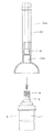
図1〜図3に示す第1の実施の形態について説明すると、図1は、洗面器、流し等の排水栓装置の排水栓部分を示している。
各図1において、符号Aは排水栓装置、100は洗面器Bに取付けられた排水口部材である。
排水栓装置Aは、洗面器B上縁面に装設された操作部からの押動操作の度にレリースワイヤを介して排水栓が上昇と下降を交互に繰り返すプッシュワンウェイ方式であり、符号Wはそのレリースワイヤ、1は上昇端でロックとロック解除を交互に行なう支持部(スラストロック機構)Sを収容するボックス、2はその支持部Sで上昇、下降を交互に繰り返す排水栓である。
The first embodiment shown in FIGS. 1 to 3 will be described. FIG. 1 shows a drain plug portion of a drain plug device such as a wash basin and a sink.
In each FIG. 1, the code | symbol A is a drain plug apparatus, 100 is the drain outlet member attached to the basin B. In FIG.
The drain plug device A is a push one-way system in which the drain plug alternately rises and lowers via a release wire every time a pushing operation is performed from the operation unit installed on the upper edge surface of the basin B. Is a release wire, 1 is a box for accommodating a support portion (thrust lock mechanism) S that alternately locks and unlocks at the rising end, and 2 is a drain plug that repeats rising and lowering alternately at the support portion S.
排水口部材100は、図1に示すように上縁に係止鍔部100aを周設した円筒状を呈し、下半部外周面に外螺子101を螺設すると共に洗面器Bのオーバーフロー路b1に面する個所同一円周上に複数個の通水口102を開口し、同図1に示すように係止鍔部100aと洗面器B底部に開口した排水口bの縁との間に鍔下パッキン103を介在した状態で三角パッキン104を押し潰すように所定トルクで締付ナット105を締結して洗面器Bの底部に設けてなり、下端に排水継手200をナット106止めして排水路300を形成している。
As shown in FIG. 1, the
前記排水口部材100の前記開口縁は従来から周知のようにホッパー状のテーパー面で形成されている。
The opening edge of the
前記排水継手200は、その上部部分にその内周面と軸芯とを結ぶ放射状リブ3を複数本架設し、そのクロスする軸芯部に前記排水栓装置Aの支持部(スラストロック機構)Sを収容する前記ボックス1を抜差し可能に係合させる係止孔4を開孔している。
The
排水栓2は、本実施の形態では栓蓋12中央から支持軸22を垂設すると共に、前記栓蓋12から放射状に振れ防止片部32を一体に突設し、その下位レベルで支持軸22に挿通してヘアーキャッチャ42を備え、栓蓋12下位の外周部にパッキン52を周設している。
In the present embodiment, the
前記栓蓋の支持軸22は、前記支持部Sの作動軸5に対して揺動可能で且つ係脱可能に係合されている。
The stopper
その具体的構成は、図2に示すように、前記支持軸22の軸芯に連通状に開孔した縦孔22aの下端に連通して設けた二段付き凹部22bと、その二段付き凹部22bの下段凹部22b−1に圧入される合成樹脂製のスリーブ状物6と、支持部Sの作動軸5に設けた環状の弧状凹部7とからなっている。
As shown in FIG. 2, the specific configuration includes a two-step recessed
前記スリーブ状物6は、合成樹脂製であり、その下半部を上半部に対して若干薄肉にして下段凹部22b−1内面との間に弾性変形隙間を確保すると共に軸方向のスリット16を周方向に等間隔をおいて切入することによってスリット16、16間に形成した弾性部26の下端に弧状凸部26aを突設して、形成されている。
このスリーブ状物6の内径は、支持部Sの作動軸5を僅かのクリアランスCを有して挿入できる程度に設定されている。
The
The inner diameter of the
前記弧状凸部26aは、弧状凹部に適合する大きさにしてあり、人為的に引っ張り力を加えた時だけ、弧状凹部7から外れるようになっている。
The arc-shaped
従って、作動軸5のスリーブ状物6とのクリアランスCだけスリーブ状物6における弾性部26の弾性機能を利用して支持軸22が作動軸5に対して揺動可能となる。
この弾性部26の弾性力は、排水栓2の自重よりも弱く設定されている。
Therefore, the
The elastic force of the
以上のように構成された洗面器、流し等の排水栓装置Aでは、前記のように栓蓋12の支持軸22が作動軸5に対して揺動可能であるので、支持部(ボックスを含む)Sに成形上の誤差、取付誤差等が生じてボックス1から突出する作動軸5の鉛直度が正確ではなくとも、排水栓2を、鉛直をもって上下動させて排水口bを開閉し、確実に止水することができる(図3参照)。
通常、支持部Sは、作動軸5が自重で落下するタイプ、その作動軸5が戻りスプリングで付勢落下するタイプのものがあり、その力を有効利用して止水することができる。
そして、係止力は、人為的な引っ張り力で支持軸が作動軸から外れる程度、例えば9.8N程度に設定されており、その力に抗して引抜くことによって栓蓋12を作動軸5から外すことができる。
尚、セット時は弾性部26が外側に開くように支持軸22を作動軸5に係止させる。
In the drain plug apparatus A such as a wash basin and a sink constructed as described above, the
In general, the support portion S includes a type in which the
The locking force is set to such an extent that the support shaft is disengaged from the operating shaft by an artificial pulling force, for example, about 9.8 N. By pulling out against the force, the
At the time of setting, the
次に図4及び図5に示す第2の実施の形態を説明すると、この実施の形態は、前記支持部Sの作動軸5に対する係止構成の変形例を示している。
Next, a second embodiment shown in FIG. 4 and FIG. 5 will be described. This embodiment shows a modified example of the locking structure of the support portion S with respect to the operating
その具体的構成は、前記作動軸5の上端に球状体15を連設する一方、前記支持軸22の下端にその球状体15を抱持する合成樹脂製の抱持部22cを設けている。
この抱持部22cは図示するように内部中空な球体における直径水平レベルの若干下位での開放部に向けて中高部位からスリット22c−1を前記実施の形態と同様に等間隔をおいて切欠してそのスリット22c−1、22c−1間に弾性部26を形成して、その弾性部26が外側に開くようにして支持軸22を作動軸5に係止させ、その弾性力に抗して引っ張ることによって球状体15に対して支持軸22が外れるようになっている。
この実施の形態の係止力は、抱持部22cに対する球状体15の摺接力であり、前記第1の実施の形態に比してその揺動時の抵抗をより小さく抑制する。
Specifically, the
As shown in the figure, the holding
The locking force of this embodiment is the sliding contact force of the
この実施の形態は、前記実施の形態に比して揺動範囲を大きくすることができる。
他の構成は前記する第1の実施の形態と同様であるため、同一符号を付して具体的説明は省略する。
In this embodiment, the swing range can be increased as compared with the above embodiment.
Since other configurations are the same as those of the first embodiment described above, the same reference numerals are given and detailed descriptions thereof are omitted.
更に、図6及び図7に示す第3の実施の形態を説明すると、この実施の形態は、支持部Sの作動軸5に対して栓蓋12の支持軸22を揺動可能に磁着させたものである。
Further, a third embodiment shown in FIGS. 6 and 7 will be described. In this embodiment, the
この実施の形態は、作動軸5または支持軸22の一方に磁石8を設け、他方に磁性体(例えば鉄)9を設けている。各々図示するように各々インサートして磁着するようにしてある。インサートせず、磁石8と支持軸または作動軸が直接磁着する構成でも良いものである。
その磁着力は、支持部(ボックスを含む)Sに成形上の誤差、取付誤差等が生じてボックス1から突出する作動軸5の鉛直度が正確ではなくとも、排水栓2が鉛直をもって上下動するように支持軸22が作動軸5に対して揺動する程度に設定して、排水口bを確実に閉塞して止水することができるようになっている。
その揺動は、支持軸22の下端に凹設されている凹部22dに先端が収容される作動軸5のその凹部22dと作動軸5との間のクリアランスCを利用して行なわれる。
また、磁着力は、人為的な引っ張り力で支持軸が作動軸から外れる程度、前記する第1、第2の実施の形態と同様に例えば9.8N程度に設定されており、その力に抗して引抜くことによって栓蓋12を作動軸5から外すことができる。
他の構成は前記する第1の実施の形態と同様であるため、同一符号を付して具体的説明は省略する。
In this embodiment, a
Even if the vertical angle of the operating
The swinging is performed using the clearance C between the
The magnetizing force is set to about 9.8 N, for example, to the extent that the support shaft is disengaged from the operating shaft by an artificial pulling force, as in the first and second embodiments described above. Then, the
Since other configurations are the same as those of the first embodiment described above, the same reference numerals are given and detailed descriptions thereof are omitted.
本発明は、支持部が作動軸を上下動可能に案内するスラストロック機構を収容しない単なる案内筒を包含するものであるし、操作部の押し引きで排水栓が上昇と下降を繰り返す排水栓装置をも包含し、また支持部がスラストロック機構等のロック機構を有するものにおいては、そのロック機構がカム機構等、その他のロック機構をも包含するものである。 The present invention includes a simple guide cylinder that does not accommodate a thrust lock mechanism in which a support portion guides an operating shaft so as to be movable up and down, and a drain plug device in which the drain plug repeatedly rises and falls by pushing and pulling the operation portion. In the case where the support portion has a lock mechanism such as a thrust lock mechanism, the lock mechanism also includes other lock mechanisms such as a cam mechanism.
A:排水栓装置 100:排水口部材
200:排水継手 300:排水路
b:排水口 1:排水栓
S:支持部 5:作動軸
12:栓蓋 22:支持軸
6:スリーブ状物 26:弾性部
26a:弧状凸部 7:弧状凹部
C:クリアランス 8: 磁石
9:磁性体
A: Drainage plug device 100: Drainage port member 200: Drainage joint 300: Drainage channel b: Drainage port 1: Drainage plug S: Support part 5: Actuation shaft 12: Cap lid 22: Support shaft 6: Sleeve-like object 26:
Claims (4)
Priority Applications (1)
| Application Number | Priority Date | Filing Date | Title |
|---|---|---|---|
| JP2003372236A JP2005133473A (en) | 2003-10-31 | 2003-10-31 | Drain plug device for wash basin, sink, and the like |
Applications Claiming Priority (1)
| Application Number | Priority Date | Filing Date | Title |
|---|---|---|---|
| JP2003372236A JP2005133473A (en) | 2003-10-31 | 2003-10-31 | Drain plug device for wash basin, sink, and the like |
Publications (1)
| Publication Number | Publication Date |
|---|---|
| JP2005133473A true JP2005133473A (en) | 2005-05-26 |
Family
ID=34648672
Family Applications (1)
| Application Number | Title | Priority Date | Filing Date |
|---|---|---|---|
| JP2003372236A Pending JP2005133473A (en) | 2003-10-31 | 2003-10-31 | Drain plug device for wash basin, sink, and the like |
Country Status (1)
| Country | Link |
|---|---|
| JP (1) | JP2005133473A (en) |
Cited By (5)
| Publication number | Priority date | Publication date | Assignee | Title |
|---|---|---|---|---|
| CN102296674A (en) * | 2011-07-21 | 2011-12-28 | 广州海鸥卫浴用品股份有限公司 | Lift-draw type drainage control device |
| JP2015071898A (en) * | 2013-10-03 | 2015-04-16 | 株式会社日本アルファ | Drain plug device |
| JP2016017382A (en) * | 2014-07-11 | 2016-02-01 | 株式会社日本アルファ | Drain plug device |
| JP2021113398A (en) * | 2020-01-16 | 2021-08-05 | 株式会社日本アルファ | Drain plug device |
| JP2021143550A (en) * | 2020-03-13 | 2021-09-24 | 丸一株式会社 | Drain plug device and method for assembling drain plug device |
-
2003
- 2003-10-31 JP JP2003372236A patent/JP2005133473A/en active Pending
Cited By (8)
| Publication number | Priority date | Publication date | Assignee | Title |
|---|---|---|---|---|
| CN102296674A (en) * | 2011-07-21 | 2011-12-28 | 广州海鸥卫浴用品股份有限公司 | Lift-draw type drainage control device |
| CN102296674B (en) * | 2011-07-21 | 2014-04-09 | 广州贝郎卫浴用品有限公司 | Lift-draw type drainage control device |
| JP2015071898A (en) * | 2013-10-03 | 2015-04-16 | 株式会社日本アルファ | Drain plug device |
| JP2016017382A (en) * | 2014-07-11 | 2016-02-01 | 株式会社日本アルファ | Drain plug device |
| JP2021113398A (en) * | 2020-01-16 | 2021-08-05 | 株式会社日本アルファ | Drain plug device |
| JP7473947B2 (en) | 2020-01-16 | 2024-04-24 | 株式会社日本アルファ | Drain plug device |
| JP2021143550A (en) * | 2020-03-13 | 2021-09-24 | 丸一株式会社 | Drain plug device and method for assembling drain plug device |
| JP7403099B2 (en) | 2020-03-13 | 2023-12-22 | 丸一株式会社 | Drain plug device and how to assemble the drain plug device |
Similar Documents
| Publication | Publication Date | Title |
|---|---|---|
| US6880179B2 (en) | Sink stopper | |
| KR20120043390A (en) | Drain plug | |
| JP2005133473A (en) | Drain plug device for wash basin, sink, and the like | |
| JPS58143029A (en) | Drain instrument | |
| CN102076573B (en) | use display closure | |
| JP5356660B2 (en) | Seal structure of drain hole of wash bowl | |
| JP5430695B2 (en) | Beverage container closure | |
| US6904623B2 (en) | Drain plug structure for bath tub | |
| JP2008025331A (en) | Drain plug device | |
| KR200311269Y1 (en) | A drainage valve having pressing-type pop-up function | |
| JP2004183226A (en) | Drainage structure | |
| JPH09316957A (en) | Hop-up type drain cock | |
| JP3749827B2 (en) | L type drainage joint | |
| JP2018119374A (en) | Valve member | |
| JP2014076377A (en) | Beverage container plug | |
| JP2002071023A (en) | Lid packing | |
| JP2010255282A (en) | Drain plug | |
| JP3922927B2 (en) | Connection structure between release wire and drain tube guide tube | |
| JP2010035443A (en) | Buffer member for float | |
| JP6893461B2 (en) | Drainage mass | |
| JP2018003485A (en) | Drain plug device | |
| JP2006063570A (en) | Connecting structure of drain plug device | |
| JPH11193562A (en) | Opening and closing device of faucet cover for drain faucet | |
| KR200469258Y1 (en) | Scupper cap of deck | |
| JP2004183225A (en) | Drain valve device |