JP2005140280A - 動力伝達機構及びその組立方法 - Google Patents
動力伝達機構及びその組立方法 Download PDFInfo
- Publication number
- JP2005140280A JP2005140280A JP2003378843A JP2003378843A JP2005140280A JP 2005140280 A JP2005140280 A JP 2005140280A JP 2003378843 A JP2003378843 A JP 2003378843A JP 2003378843 A JP2003378843 A JP 2003378843A JP 2005140280 A JP2005140280 A JP 2005140280A
- Authority
- JP
- Japan
- Prior art keywords
- adapter
- shaft
- screw portion
- drive shaft
- power transmission
- Prior art date
- Legal status (The legal status is an assumption and is not a legal conclusion. Google has not performed a legal analysis and makes no representation as to the accuracy of the status listed.)
- Granted
Links
- 230000005540 biological transmission Effects 0.000 title claims abstract description 63
- 238000000034 method Methods 0.000 title claims description 8
- 230000002093 peripheral effect Effects 0.000 claims abstract description 26
- 239000012530 fluid Substances 0.000 claims description 12
- 239000011295 pitch Substances 0.000 description 21
- 239000003507 refrigerant Substances 0.000 description 21
- XEEYBQQBJWHFJM-UHFFFAOYSA-N Iron Chemical compound [Fe] XEEYBQQBJWHFJM-UHFFFAOYSA-N 0.000 description 6
- 239000007769 metal material Substances 0.000 description 4
- 229910052742 iron Inorganic materials 0.000 description 3
- 238000007789 sealing Methods 0.000 description 3
- 230000000694 effects Effects 0.000 description 2
- 239000000463 material Substances 0.000 description 2
- 230000006835 compression Effects 0.000 description 1
- 238000007906 compression Methods 0.000 description 1
- 230000003247 decreasing effect Effects 0.000 description 1
- 230000005489 elastic deformation Effects 0.000 description 1
- 238000005516 engineering process Methods 0.000 description 1
Images


Classifications
-
- F—MECHANICAL ENGINEERING; LIGHTING; HEATING; WEAPONS; BLASTING
- F16—ENGINEERING ELEMENTS AND UNITS; GENERAL MEASURES FOR PRODUCING AND MAINTAINING EFFECTIVE FUNCTIONING OF MACHINES OR INSTALLATIONS; THERMAL INSULATION IN GENERAL
- F16D—COUPLINGS FOR TRANSMITTING ROTATION; CLUTCHES; BRAKES
- F16D1/00—Couplings for rigidly connecting two coaxial shafts or other movable machine elements
- F16D1/06—Couplings for rigidly connecting two coaxial shafts or other movable machine elements for attachment of a member on a shaft or on a shaft-end
-
- F—MECHANICAL ENGINEERING; LIGHTING; HEATING; WEAPONS; BLASTING
- F16—ENGINEERING ELEMENTS AND UNITS; GENERAL MEASURES FOR PRODUCING AND MAINTAINING EFFECTIVE FUNCTIONING OF MACHINES OR INSTALLATIONS; THERMAL INSULATION IN GENERAL
- F16H—GEARING
- F16H55/00—Elements with teeth or friction surfaces for conveying motion; Worms, pulleys or sheaves for gearing mechanisms
- F16H55/32—Friction members
- F16H55/36—Pulleys
Landscapes
- Engineering & Computer Science (AREA)
- General Engineering & Computer Science (AREA)
- Mechanical Engineering (AREA)
- Applications Or Details Of Rotary Compressors (AREA)
- Transmission Devices (AREA)
- Pulleys (AREA)
Abstract
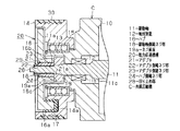
【解決手段】 駆動軸11の外周面には、駆動軸側雄ネジ部18が形成されているとともにネジ座面19aが設けられている。駆動軸11において駆動軸側雄ネジ部18の外側には、円筒状のアダプタ21が配置されている。アダプタ21の内周面に形成されたアダプタ側雌ネジ部22は、駆動軸側雄ネジ部18に螺合されている。アダプタ21の外周面に形成されたアダプタ側雄ネジ部23には、ハブ16に形成されたハブ側雌ネジ部24が螺合されている。そして、これら螺合によって、ネジ座面19aに対してハブ16が押し付けられることで、該ハブ16と駆動軸11とが締結固定されている。
【選択図】 図1
Description
(従来技術)
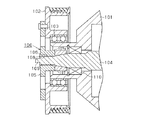
図4に示すように、前記ハブ105から駆動軸104へのトルクの伝達は、ネジ座部材107を介する経路と、ハブ側雌ネジ部108及び駆動軸側雄ネジ部106を介する経路のそれぞれで行われる。従って、ハブ105から駆動軸104へ伝達されるトルクの最大値(最大トルク)を「T(max)」とし、ハブ105からネジ座部材107に伝達されるトルクを「T(1)」とし、ハブ側雌ネジ部108から駆動軸側雄ネジ部106に伝達されるトルクを「T(2)」とすると、「T(max)=T(1)+T(2)」と表せる。また、ハブ105から駆動軸104への最大トルクT(max)の伝達を可能とするためには、駆動軸104とハブ105との締付けトルクを最大トルクT(max)以上とする必要がある。
図2に示すように、前記ハブ16から駆動軸11へのトルクの伝達は、ボス部16bの先端面16c及びネジ座部材19のネジ座面19aを介する経路と、ハブ側雌ネジ部24及びアダプタ21のアダプタ側雄ネジ部23を介する経路のそれぞれで行われる。アダプタ21から駆動軸11へのトルクの伝達は、アダプタ側雌ネジ部22及び駆動軸側雄ネジ部18を介する経路と、アダプタ21の端面21a及びネジ座部材19のネジ座面19aを介する経路のそれぞれで行われる。
(1)駆動軸側雄ネジ部18及びアダプタ側雌ネジ部22のネジピッチと、アダプタ側雄ネジ部23及びハブ側雌ネジ部24のネジピッチとは異なっている。従って、例えば、冷媒圧縮機Cの運転時においてアダプタ21に外力が作用しても、該アダプタ21がハブ16及び駆動軸11に対して相対螺進することを抑制でき、例えば駆動軸11及びハブ16からのアダプタ21の抜けを防止することができる。
○上記実施形態を変更し、前記駆動軸側雄ネジ部18及びアダプタ側雌ネジ部22のネジピッチと、アダプタ側雄ネジ部23及びハブ側雌ネジ部24のネジピッチとを異ならせるにあたり、駆動軸側雄ネジ部18及びアダプタ側雌ネジ部22のネジピッチを、アダプタ側雄ネジ部23及びハブ側雌ネジ部24のネジピッチよりも大きくすること。このようにすれば、駆動軸側雄ネジ部18及びアダプタ側雌ネジ部22のネジピッチに対して相関関係を有する各ネジ部18,22のネジ山を大きくして互いの接触面積を広くすることができ、アダプタ21と駆動軸11との間での伝達トルクに占める、駆動軸側雄ネジ部18とアダプタ側雌ネジ部22との間での分担を大きくすることができる。
(1)前記シャフト及び前記回転体並びに前記アダプタは同種の材料よりなっている請求項1〜6のいずれか一項に記載の動力伝達機構。
Claims (7)
- シャフトと該シャフトに連結された回転体との間で動力伝達を行う動力伝達機構であって、前記シャフトの外周面にはシャフト側雄ネジ部が形成されているとともにネジ座面が設けられ、前記シャフトにおいて前記シャフト側雄ネジ部の外側には円筒状のアダプタが配置され、該アダプタの内周面に形成されたアダプタ側雌ネジ部は前記シャフト側雄ネジ部に螺合され、前記アダプタの外周面に形成されたアダプタ側雄ネジ部には前記回転体に形成された回転体側雌ネジ部が螺合されており、これら螺合によって前記ネジ座面に対して前記回転体が押し付けられることで、該回転体と前記シャフトとが締結固定されていることを特徴とする動力伝達機構。
- 前記シャフト側雄ネジ部及び前記アダプタ側雌ネジ部のネジピッチと、前記アダプタ側雄ネジ部及び前記回転体側雌ネジ部のネジピッチとは異なっている請求項1に記載の動力伝達機構。
- 前記シャフト側雄ネジ部及び前記アダプタ側雌ネジ部のネジピッチは、前記アダプタ側雄ネジ部及び前記回転体側雌ネジ部のネジピッチよりも小さい請求項2に記載の動力伝達機構。
- 前記シャフト側雄ネジ部及び前記アダプタ側雌ネジ部のネジピッチは、前記アダプタ側雄ネジ部及び前記回転体側雌ネジ部のネジピッチよりも大きい請求項2に記載の動力伝達機構。
- 前記シャフトは流体機械の駆動軸であって該流体機械には前記駆動軸を封止する軸封装置が備えられており、前記駆動軸へ動力を入力するための前記回転体は、前記軸封装置よりも機外側で前記駆動軸に締結固定されている請求項1〜4のいずれか一項に記載の動力伝達機構。
- 前記シャフトにおいて前記ネジ座面が向かう側に位置する端部には、前記シャフトと前記アダプタとの螺合作業時において組立機械のチャックがくわえるための回り止め部が設けられており、該回り止め部は前記シャフト側雄ネジ部よりも小径とされている請求項1〜5のいずれか一項に記載の動力伝達機構。
- 請求項1〜6のいずれか一項に記載の動力伝達機構の組立方法であって、前記シャフトと前記アダプタとを相対回転させることで、前記シャフト側雄ネジ部と前記アダプタ側雌ネジ部とを螺合する第1工程と、前記アダプタと前記回転体とを相対回転させることで、前記アダプタ側雄ネジ部と前記回転体側雌ネジ部とを螺合して前記ネジ座面に前記回転体を押し付ける第2工程とからなることを特徴とする動力伝達機構の組立方法。
Priority Applications (4)
| Application Number | Priority Date | Filing Date | Title |
|---|---|---|---|
| JP2003378843A JP4100329B2 (ja) | 2003-11-07 | 2003-11-07 | 動力伝達機構及びその組立方法 |
| US10/979,676 US7374407B2 (en) | 2003-11-07 | 2004-11-02 | Power transmission mechanism and process of assembling the same |
| EP04026185A EP1529977B1 (en) | 2003-11-07 | 2004-11-04 | Power transmission mechanism and process of assembling the same |
| DE602004004975T DE602004004975T2 (de) | 2003-11-07 | 2004-11-04 | Kraftübertragungsmechanismus und Verfahren zum Zusammensetzen eines solchen Mechanismus |
Applications Claiming Priority (1)
| Application Number | Priority Date | Filing Date | Title |
|---|---|---|---|
| JP2003378843A JP4100329B2 (ja) | 2003-11-07 | 2003-11-07 | 動力伝達機構及びその組立方法 |
Publications (2)
| Publication Number | Publication Date |
|---|---|
| JP2005140280A true JP2005140280A (ja) | 2005-06-02 |
| JP4100329B2 JP4100329B2 (ja) | 2008-06-11 |
Family
ID=34431361
Family Applications (1)
| Application Number | Title | Priority Date | Filing Date |
|---|---|---|---|
| JP2003378843A Expired - Fee Related JP4100329B2 (ja) | 2003-11-07 | 2003-11-07 | 動力伝達機構及びその組立方法 |
Country Status (4)
| Country | Link |
|---|---|
| US (1) | US7374407B2 (ja) |
| EP (1) | EP1529977B1 (ja) |
| JP (1) | JP4100329B2 (ja) |
| DE (1) | DE602004004975T2 (ja) |
Cited By (1)
| Publication number | Priority date | Publication date | Assignee | Title |
|---|---|---|---|---|
| KR101207308B1 (ko) | 2005-11-07 | 2012-12-03 | 한라공조주식회사 | 하이브리드용 동력전달장치 |
Families Citing this family (7)
| Publication number | Priority date | Publication date | Assignee | Title |
|---|---|---|---|---|
| JP2008223945A (ja) * | 2007-03-14 | 2008-09-25 | Toyota Industries Corp | 圧縮機の動力伝達装置 |
| JP2008232206A (ja) | 2007-03-19 | 2008-10-02 | Toyota Industries Corp | 圧縮機の動力伝達装置 |
| US7901194B2 (en) * | 2008-04-09 | 2011-03-08 | Hamilton Sundstrand Corporation | Shaft coupling for scroll compressor |
| DE102009014718A1 (de) * | 2009-03-27 | 2010-09-30 | Astrium Gmbh | Vorrichtung zur Feineinstellung des Abstandes zwischen zwei Elementen |
| CN104675700B (zh) * | 2013-10-31 | 2017-04-19 | 大金工业株式会社 | 螺杆压缩机 |
| CN112879538B (zh) * | 2021-01-11 | 2022-11-18 | 山东百昌汽车零部件有限公司 | 一种防止高速运转松动的驱动轴组件 |
| US20250314288A1 (en) * | 2024-04-09 | 2025-10-09 | Cnh Industrial America Llc | Drive pulley adapter for a belt driven component |
Family Cites Families (8)
| Publication number | Priority date | Publication date | Assignee | Title |
|---|---|---|---|---|
| US2269799A (en) * | 1939-09-23 | 1942-01-13 | Torrington Mfg Co | Fan hub and shaft assembly |
| JPH0727121A (ja) | 1993-06-30 | 1995-01-27 | Jacobs Japan Inc | 締付け用ネジ |
| JP4038948B2 (ja) | 1999-10-22 | 2008-01-30 | 株式会社デンソー | 動力伝達装置 |
| JP2003013995A (ja) * | 2001-06-28 | 2003-01-15 | Toyota Industries Corp | 動力伝達機構および圧縮機 |
| JP2003028183A (ja) | 2001-07-13 | 2003-01-29 | Toyota Industries Corp | 動力伝達部材の締結構造 |
| JP2003035255A (ja) | 2001-07-23 | 2003-02-07 | Toyota Industries Corp | 動力伝達部材の締結構造 |
| JP3928405B2 (ja) | 2001-10-24 | 2007-06-13 | 株式会社デンソー | 回転体と回転軸との締結構造 |
| DE10317116B4 (de) * | 2002-04-16 | 2019-07-25 | Denso Corporation | Kupplungseinrichtung |
-
2003
- 2003-11-07 JP JP2003378843A patent/JP4100329B2/ja not_active Expired - Fee Related
-
2004
- 2004-11-02 US US10/979,676 patent/US7374407B2/en not_active Expired - Fee Related
- 2004-11-04 DE DE602004004975T patent/DE602004004975T2/de not_active Expired - Lifetime
- 2004-11-04 EP EP04026185A patent/EP1529977B1/en not_active Expired - Lifetime
Cited By (1)
| Publication number | Priority date | Publication date | Assignee | Title |
|---|---|---|---|---|
| KR101207308B1 (ko) | 2005-11-07 | 2012-12-03 | 한라공조주식회사 | 하이브리드용 동력전달장치 |
Also Published As
| Publication number | Publication date |
|---|---|
| JP4100329B2 (ja) | 2008-06-11 |
| DE602004004975D1 (de) | 2007-04-12 |
| US7374407B2 (en) | 2008-05-20 |
| EP1529977B1 (en) | 2007-02-28 |
| DE602004004975T2 (de) | 2007-11-08 |
| US20050100397A1 (en) | 2005-05-12 |
| EP1529977A1 (en) | 2005-05-11 |
Similar Documents
| Publication | Publication Date | Title |
|---|---|---|
| KR20030061293A (ko) | 토크 리미터 | |
| US7125191B2 (en) | Power transmission device | |
| JP4100329B2 (ja) | 動力伝達機構及びその組立方法 | |
| JP2009030739A (ja) | 波動歯車装置 | |
| JP2006183527A (ja) | 流体機械 | |
| EP1933061A1 (en) | Power transmission device of a compressor | |
| JP2009257543A (ja) | 回転軸連結構造及びギヤドモータ | |
| US7303478B2 (en) | Power transmission mechanism capable of preventing breakage of a rotating shaft | |
| JP2012041969A (ja) | 等速自在継手用ブーツ及び等速自在継手 | |
| WO2011013433A1 (ja) | 自在継手用ブーツ | |
| JP2007120558A (ja) | 機械装置のネジカバーの緩み止め構造 | |
| JP2006077939A (ja) | 動力伝達装置 | |
| EP1972811A2 (en) | Power transmission device of a compressor | |
| JP2010121704A (ja) | ブーツ取付構造 | |
| JP2006234116A (ja) | プーリ | |
| JP2008045675A (ja) | 等速自在継手のブーツ装着構造 | |
| JP2009092108A (ja) | 回転体と回転軸の締結構造 | |
| JP2004019495A (ja) | 動力伝達機構の位置決め構造 | |
| JP2005053388A (ja) | 電動パワーステアリング装置 | |
| JP2009127762A (ja) | 等速自在継手 | |
| JP2007177923A (ja) | 継手用ブーツ | |
| JP2005351307A (ja) | 圧縮機の締結装置 | |
| JP2003028183A (ja) | 動力伝達部材の締結構造 | |
| JP2008064192A (ja) | 流体伝動装置の連結構造 | |
| WO2014157276A1 (ja) | 動力伝達装置 |
Legal Events
| Date | Code | Title | Description |
|---|---|---|---|
| A621 | Written request for application examination |
Free format text: JAPANESE INTERMEDIATE CODE: A621 Effective date: 20060119 |
|
| A977 | Report on retrieval |
Free format text: JAPANESE INTERMEDIATE CODE: A971007 Effective date: 20080221 |
|
| TRDD | Decision of grant or rejection written | ||
| A01 | Written decision to grant a patent or to grant a registration (utility model) |
Free format text: JAPANESE INTERMEDIATE CODE: A01 Effective date: 20080226 |
|
| A61 | First payment of annual fees (during grant procedure) |
Free format text: JAPANESE INTERMEDIATE CODE: A61 Effective date: 20080310 |
|
| FPAY | Renewal fee payment (event date is renewal date of database) |
Free format text: PAYMENT UNTIL: 20110328 Year of fee payment: 3 |
|
| LAPS | Cancellation because of no payment of annual fees |