JP2005142000A - Fuel cell - Google Patents
Fuel cell Download PDFInfo
- Publication number
- JP2005142000A JP2005142000A JP2003376379A JP2003376379A JP2005142000A JP 2005142000 A JP2005142000 A JP 2005142000A JP 2003376379 A JP2003376379 A JP 2003376379A JP 2003376379 A JP2003376379 A JP 2003376379A JP 2005142000 A JP2005142000 A JP 2005142000A
- Authority
- JP
- Japan
- Prior art keywords
- fuel cell
- separator
- electrode structure
- seal member
- suction
- Prior art date
- Legal status (The legal status is an assumption and is not a legal conclusion. Google has not performed a legal analysis and makes no representation as to the accuracy of the status listed.)
- Withdrawn
Links
Images





Classifications
-
- Y—GENERAL TAGGING OF NEW TECHNOLOGICAL DEVELOPMENTS; GENERAL TAGGING OF CROSS-SECTIONAL TECHNOLOGIES SPANNING OVER SEVERAL SECTIONS OF THE IPC; TECHNICAL SUBJECTS COVERED BY FORMER USPC CROSS-REFERENCE ART COLLECTIONS [XRACs] AND DIGESTS
- Y02—TECHNOLOGIES OR APPLICATIONS FOR MITIGATION OR ADAPTATION AGAINST CLIMATE CHANGE
- Y02E—REDUCTION OF GREENHOUSE GAS [GHG] EMISSIONS, RELATED TO ENERGY GENERATION, TRANSMISSION OR DISTRIBUTION
- Y02E60/00—Enabling technologies; Technologies with a potential or indirect contribution to GHG emissions mitigation
- Y02E60/30—Hydrogen technology
- Y02E60/50—Fuel cells
Landscapes
- Fuel Cell (AREA)
Abstract
【課題】簡単な構成で、セパレータ同士又は前記セパレータと電解質・電極構造体とを互いに保持することができ、組み立て作業を容易且つ効率的に遂行することを可能にする。
【解決手段】電解質膜・電極構造体12を第1及び第2金属セパレータ14、16で挟持するとともに、前記第1及び第2金属セパレータ14には、それぞれ第1及び第2シール部材40、48が一体化される。第1シール部材40は、吸着盤44を一体的に成形しており、この吸着盤44は、第2シール部材48の面に押し付けられることにより、第2金属セパレータ16を吸着する。このため、第1及び第2金属セパレータ14、16は、吸着盤44の吸引作用下に互いに保持される。
【選択図】図2
The present invention enables a separator to hold each other or the separator and an electrolyte / electrode structure to each other with a simple configuration, and enables an assembly operation to be performed easily and efficiently.
An electrolyte membrane / electrode structure 12 is sandwiched between first and second metal separators 14 and 16, and first and second seal members 40 and 48 are respectively attached to the first and second metal separators 14. Are integrated. The first seal member 40 integrally forms a suction plate 44, and the suction plate 44 sucks the second metal separator 16 by being pressed against the surface of the second seal member 48. For this reason, the first and second metal separators 14 and 16 are held together under the suction action of the suction disk 44.
[Selection] Figure 2
Description
本発明は、電解質の両側に一対の電極を設けた電解質・電極構造体を、一対のセパレータで挟持して構成される燃料電池に関する。 The present invention relates to a fuel cell configured by sandwiching an electrolyte / electrode structure provided with a pair of electrodes on both sides of an electrolyte with a pair of separators.
例えば、固体高分子型燃料電池は、高分子イオン交換膜からなる固体高分子電解質膜の両側に、それぞれアノード側電極及びカソード側電極を対設した電解質膜・電極構造体(電解質・電極構造体)を、セパレータによって挟持することにより単位セルとして構成されている。 For example, a polymer electrolyte fuel cell has an electrolyte membrane / electrode structure (an electrolyte / electrode structure) in which an anode side electrode and a cathode side electrode are provided on both sides of a solid polymer electrolyte membrane made of a polymer ion exchange membrane, respectively. ) Are sandwiched between separators to constitute a unit cell.
この単位セルにおいて、アノード側電極に供給された燃料ガス、例えば、主に水素を含有するガス(以下、水素含有ガスともいう)は、電極触媒上で水素がイオン化され、電解質膜を介してカソード側電極側へと移動する。その間に生じた電子は外部回路に取り出され、直流の電気エネルギとして利用される。なお、カソード側電極には、酸化剤ガス、例えば、主に酸素を含有するガスあるいは空気(以下、酸素含有ガスともいう)が供給されているために、このカソード側電極において、水素イオン、電子及び酸素が反応して水が生成される。 In this unit cell, a fuel gas supplied to the anode side electrode, for example, a gas mainly containing hydrogen (hereinafter also referred to as a hydrogen-containing gas) is ionized with hydrogen on the electrode catalyst, and the cathode passes through the electrolyte membrane. Move to the side electrode side. Electrons generated during that time are taken out to an external circuit and used as direct current electric energy. The cathode side electrode is supplied with an oxidant gas, for example, a gas mainly containing oxygen or air (hereinafter also referred to as an oxygen-containing gas). And oxygen reacts to produce water.
ところで、燃料電池は、通常、数十〜数百の単位セルを積層してスタックを構成している。その際、各単位セル同士を正確に位置決めする必要があり、このため、前記単位セルに形成された位置決め用孔部にノックピンを挿入する作業が行われている。しかしながら、単位セルの積層数が増加するのに伴って、ノックピンの挿入作業が困難なものとなり、作業性が低下するとともに、部材の位置ずれが惹起し易く、シール機能が低下するという問題がある。 By the way, the fuel cell normally forms a stack by stacking several tens to several hundreds of unit cells. At that time, it is necessary to accurately position each unit cell, and therefore, an operation of inserting a knock pin into a positioning hole formed in the unit cell is performed. However, as the number of stacked unit cells increases, the operation of inserting the knock pin becomes difficult, the workability is lowered, the position of the member is easily displaced, and the sealing function is lowered. .
そこで、上記の問題を解決するために、例えば、特許文献1の電気化学燃料電池アセンブリが知られている。具体的には、図12に示すように、電気化学燃料電池アセンブリ1は、電解質膜・電極構造体2と、この電解質膜・電極構造体2を挟んで配置される第1及び第2プレート3a、3bとを備えている。電解質膜・電極構造体2は、アノード電極4の両側にイオン交換膜5a、5bを介装してカソード電極6a、6bを積層している。
In order to solve the above problem, for example, an electrochemical fuel cell assembly of
第1及び第2プレート3a、3bの両端には、それぞれマウントレール7a、7bが設けられている。各マウントレール7a、7bには、複数の捻りワイヤスプリング8が取り付けられており、電解質膜・電極構造体2に締め付け荷重を付与している。
しかしながら、上記の特許文献1では、数十〜数百の単位セルに対して、それぞれ複数の捻りワイヤスプリング8を取り付ける作業が必要になり、この取り付け作業が相当に煩雑化するという問題がある。
However, in the above-mentioned
一方、この種の作業を自動化しようとしても、第1及び第2プレート3a、3b間に電解質膜・電極構造体2を介装した後、これらに荷重を付与して内部に組み込まれているシール部材を圧縮した状態で、複数の捻りワイヤスプリング8をマウントレール7a、7bに取り付ける工程が必要である。これにより、作業時間が有効に短縮されず、しかも設備費が高騰して経済的ではないという問題が指摘されている。
On the other hand, even if it is going to automate this kind of work, after the electrolyte membrane /
また、第1及び第2プレート3a、3b間には、発電時に電位差が発生するため、前記第1及び第2プレート3a、3bが捻りワイヤスプリング8を介して電気的に短絡することを阻止しなければならない。従って、捻りワイヤスプリング8、第1及び第2プレート3a、3b又はこれらの間に、絶縁構造を設ける必要があり、経済的ではないという問題がある。
In addition, since a potential difference is generated between the first and
さらに、第1及び第2プレート3a、3bの外部に捻りワイヤスプリング8が取り付けられている。このため、この状態で発電を行う場合には、捻りワイヤスプリング8が外部スペースを専有してしまい、電気化学燃料電池アセンブリ1の小型化を図ることができない。
Further, a
さらにまた、捻りワイヤスプリング8の圧縮力だけで、シール機能と通電機能とを得ようとすると、該圧縮力によって構成部品が変形しないように、剛性を確保する必要がある。これにより、第1及び第2プレート3a、3b自体の厚さを薄肉に構成することができず、電気化学燃料電池アセンブリ1を小型化することができないという問題がある。
Furthermore, if it is attempted to obtain a sealing function and an energization function only with the compressive force of the
本発明はこの種の問題を解決するものであり、簡単な構成で、セパレータ同士又は前記セパレータと電解質・電極構造体とを互いに保持することができ、組み立て作業を容易且つ効率的に遂行することが可能な燃料電池を提供することを目的とする。 The present invention solves this type of problem, and with a simple configuration, the separators or the separator and the electrolyte / electrode structure can be held together, and the assembly operation can be performed easily and efficiently. An object of the present invention is to provide a fuel cell capable of satisfying the requirements.
本発明の燃料電池では、電解質の両側に一対の電極を設けた電解質・電極構造体を、一対のセパレータで挟持して構成されるとともに、少なくとも一方のセパレータ又は前記電解質・電極構造体には、2枚のセパレータ同士又は該セパレータと該電解質・電極構造体とを互いに保持するための弾性変形可能な吸盤構造が設けられている。 In the fuel cell of the present invention, an electrolyte / electrode structure provided with a pair of electrodes on both sides of the electrolyte is sandwiched between a pair of separators, and at least one separator or the electrolyte / electrode structure includes: An elastically deformable suction cup structure is provided to hold the two separators or the separator and the electrolyte / electrode structure together.
具体的には、一方のセパレータの電解質・電極構造体に向かう面には、吸盤構造が設けられている。そして、一方のセパレータと他方のセパレータとの間に電解質・電極構造体が配置された状態で、吸盤構造を介して前記セパレータ同士が保持される。従って、電解質・電極構造体と一対のセパレータとを有する燃料電池(単位セル)が、一体化される。 Specifically, a suction cup structure is provided on the surface of one separator facing the electrolyte / electrode structure. And the said separators are hold | maintained through a suction cup structure in the state which has arrange | positioned the electrolyte and electrode structure between one separator and the other separator. Therefore, the fuel cell (unit cell) having the electrolyte / electrode structure and the pair of separators is integrated.
また、一方のセパレータの電解質・電極構造体と反対の面には、吸盤構造が設けられている。このため、積層される燃料電池を構成し互いに隣接する各セパレータ同士が、吸盤構造を介して保持される。 Further, a suction cup structure is provided on the surface of one separator opposite to the electrolyte / electrode structure. For this reason, each separator which comprises the fuel cell laminated | stacked and adjoins mutually is hold | maintained via a suction cup structure.
さらに、電解質・電極構造体に吸盤構造が設けられていると、この吸盤構造を介して前記電解質・電極構造体とセパレータとが保持される。さらにまた、少なくとも一方のセパレータと電解質・電極構造体とに、それぞれ吸盤構造が設けられている。従って、セパレータ同士は、一方の吸盤構造により保持されるとともに、前記セパレータと電解質・電極構造体とが他方の吸盤構造により保持される。これにより、単位セルが一体化される。 Further, when the electrolyte / electrode structure is provided with a suction cup structure, the electrolyte / electrode structure and the separator are held via the suction cup structure. Furthermore, at least one separator and the electrolyte / electrode structure are each provided with a suction cup structure. Accordingly, the separators are held by one suction cup structure, and the separator and the electrolyte / electrode structure are held by the other suction cup structure. As a result, the unit cells are integrated.
また、吸盤構造は、少なくともセパレータ又は電解質・電極構造体のいずれかにシール部材と一体的に成形されることが好ましい。さらに、吸盤構造は、少なくともセパレータ又は電解質・電極構造体のいずれかに取り付けられることが好ましい。 In addition, the suction cup structure is preferably formed integrally with the seal member at least on either the separator or the electrolyte / electrode structure. Furthermore, the suction cup structure is preferably attached to at least either the separator or the electrolyte / electrode structure.
本発明に係る燃料電池では、吸盤構造の吸着作用下に、燃料電池の構成部品同士が保持されるため、クリップ等の固定具を燃料電池に装着する必要がなく、前記燃料電池の組み立て作業を容易且つ効率的に遂行することが可能になる。特に、多数の燃料電池を積層する際には、積層作業が良好に遂行されて燃料電池スタックを迅速に構成することができる。 In the fuel cell according to the present invention, since the components of the fuel cell are held together under the suction action of the suction cup structure, there is no need to attach a fixture such as a clip to the fuel cell, and the assembly operation of the fuel cell is performed. It becomes possible to carry out easily and efficiently. In particular, when a large number of fuel cells are stacked, the stacking operation can be performed satisfactorily to quickly configure the fuel cell stack.
しかも、吸盤構造は、燃料電池内部に設置されるため、この燃料電池の外部に固定具が露呈することがない。従って、燃料電池全体をコンパクトに構成するとともに、前記燃料電池の設置スペースが可及的に狭小化される。このため、特に車載用の燃料電池スタックとして有効に適用することが可能になる。 Moreover, since the suction cup structure is installed inside the fuel cell, the fixture is not exposed to the outside of the fuel cell. Accordingly, the entire fuel cell is made compact, and the installation space for the fuel cell is made as narrow as possible. For this reason, it becomes possible to apply effectively especially as a fuel cell stack for vehicles.
さらに、吸盤構造は、シール部材と一体的に樹脂材で構成されるため、所望の絶縁機能を有するとともに、加工作業が簡素化される。これにより、燃料電池全体の構成が簡素化され、経済的である。 Furthermore, since the suction cup structure is made of a resin material integrally with the seal member, it has a desired insulating function and simplifies the processing work. Thereby, the structure of the whole fuel cell is simplified and it is economical.
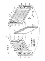
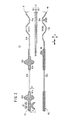
図1は、本発明の第1の実施形態に係る燃料電池10の要部分解斜視説明図であり、図2は、前記燃料電池10の、図1中、II−II線断面図である。
FIG. 1 is an exploded perspective view of a main part of a
図1に示すように、燃料電池10は、電解質膜・電極構造体(電解質・電極構造体)12が、第1及び第2金属セパレータ14、16に挟持されて構成される。第1及び第2金属セパレータ14、16は、例えば、鋼板、ステンレス鋼板、アルミニウム板、めっき処理鋼板、あるいはその金属表面に防食用の表面処理を施した金属板により構成されている。なお、第1及び第2金属セパレータ14、16に代替して、例えば、カーボンや樹脂で構成されるセパレータを使用してもよい。
As shown in FIG. 1, the
燃料電池10の矢印B方向(図1中、水平方向)の一端縁部には、積層方向である矢印A方向に互いに連通して、酸化剤ガス、例えば、酸素含有ガスを供給するための酸化剤ガス入口連通孔20a、冷却媒体を排出するための冷却媒体出口連通孔22b、及び燃料ガス、例えば、水素含有ガスを排出するための燃料ガス出口連通孔24bが、矢印C方向(鉛直方向)に配列して設けられる。
One end edge of the
燃料電池10の矢印B方向の他端縁部には、矢印A方向に互いに連通して、燃料ガスを供給するための燃料ガス入口連通孔24a、冷却媒体を供給するための冷却媒体入口連通孔22a、及び酸化剤ガスを排出するための酸化剤ガス出口連通孔20bが、矢印C方向に配列して設けられる。
The other end edge in the direction of arrow B of the
電解質膜・電極構造体12は、例えば、パーフルオロスルホン酸の薄膜に水が含浸された固体高分子電解質膜26と、前記固体高分子電解質膜26を挟持するアノード側電極28及びカソード側電極30とを備える。アノード側電極28は、カソード側電極30よりも小さな表面積を有している。
The electrolyte membrane /
アノード側電極28及びカソード側電極30は、カーボンペーパ等からなるガス拡散層と、白金合金が表面に担持された多孔質カーボン粒子が前記ガス拡散層の表面に一様に塗布された電極触媒層とを有する。電極触媒層は、固体高分子電解質膜26の両面に接合されている。
The
第1金属セパレータ14のカソード側電極30に対向する面14aには、酸化剤ガス入口連通孔20aと酸化剤ガス出口連通孔20bとに連通し、例えば、矢印B方向に延在する直線状の酸化剤ガス流路32が設けられる。第2金属セパレータ16のアノード側電極28に対向する面16aには、燃料ガス入口連通孔24aと燃料ガス出口連通孔24bとに連通し、矢印B方向に延在する直線状の燃料ガス流路34が形成される。
The
第1金属セパレータ14の面14bと第2金属セパレータ16の面16bとの間には、冷却媒体入口連通孔22aと冷却媒体出口連通孔22bとに連通する冷却媒体流路36が形成される。この冷却媒体流路36は、矢印B方向に直線状に延在する。
Between the
第1金属セパレータ14の面14a、14bには、この第1金属セパレータ14の外周端部を周回して第1シール部材40が、例えば、射出成形等により一体化される。第1シール部材40は、例えば、EPDM、NBR、フッ素ゴム、シリコーンゴム、フロロシリコーンゴム、ブチルゴム、天然ゴム、スチレンゴム、クロロプレーン、又はアクリルゴム等のシール材、クッション材、あるいはパッキン材を使用する。
The
図1及び図2に示すように、第1金属セパレータ14の面14aには、この第1金属セパレータ14の外周端部に近接して第1シール部材40を構成する突部42aが一体化される。突部42aは、電解質膜・電極構造体12の外周を囲繞するとともに、酸化剤ガス流路32と酸化剤ガス入口連通孔20a及び酸化剤ガス出口連通孔20bとを連通する。
As shown in FIGS. 1 and 2, a
第1金属セパレータ14の面14aには、弾性変形可能な吸着盤(吸盤構造)44が設けられる。吸着盤44は、第1シール部材40と一体的に成形されており、図1に示すように、第1金属セパレータ14の四隅及び上下両辺中央部の合計6個所に設けられる。
The
図2に示すように、吸着盤44は、第1シール部材40と一体化されてこの第1シール部材40の面から突出する首部46aを有し、この首部46aには、湾曲するカップ部46bが一体成形されている。第1シール部材40の面からカップ部46bの先端までの高さHは、この第1シール部材40の面から突部42aの先端までの高さH1よりも大きく設定される(H>H1)。
As shown in FIG. 2, the
図1及び図2に示すように、第2金属セパレータ16の面16a、16bには、この第2金属セパレータ16の外周端部を周回して第2シール部材48が一体化される。この第2シール部材48は、上記の第1シール部材40と同一の材料で構成される。第2金属セパレータ16の面16aには、第2シール部材48を構成する突部50が一体化される。この突部50は、電解質膜・電極構造体12を構成する固体高分子電解質膜26の外周縁部に密着する。
As shown in FIGS. 1 and 2, the
次に、このように構成される燃料電池10を組み付ける作業について、以下に説明する。
Next, the operation of assembling the
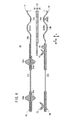
先ず、図2に示すように、電解質膜・電極構造体12を挟んで、第1及び第2金属セパレータ14、16が配設される。この状態で、第1及び第2金属セパレータ14、16に押し付け荷重が付与されると、吸着盤44のカップ部46bが第2金属セパレータ16の第2シール部材48に接触する。従って、カップ部46bは、押し付け荷重により変形して第2金属セパレータ16を吸着し、第1及び第2金属セパレータ14、16同士は、電解質膜・電極構造体12を挟んで互いに保持される(図3参照)。
First, as shown in FIG. 2, the first and
このように、燃料電池10を構成する電解質膜・電極構造体12と第1及び第2金属セパレータ14、16とは、複数(例えば、6つ)の吸着盤44の吸引作用下に一体化される。これにより、第1の実施形態では、クリップ等の固定具を燃料電池10に装着する必要がなく、前記燃料電池10の組み立て作業を容易且つ効率的に遂行することが可能になるという効果が得られる。
As described above, the electrolyte membrane /
特に、多数の燃料電池10を積層する際には、該燃料電池10の積層作業を良好に遂行することができ、燃料電池スタック52を迅速に構成することが可能になるという利点がある(図3参照)。
In particular, when a large number of
しかも、吸着盤44は、第1金属セパレータ14の面14a内に設けられるため、燃料電池10の外部に固定具が露呈することがない。従って、燃料電池10全体をコンパクトに構成するとともに、前記燃料電池10の設置スペースが可及的に狭小化され、例えば、車載用燃料電池スタック52として良好に使用することができる。
Moreover, since the
さらに、吸着盤44は、第1シール部材40と一体的に樹脂材で構成されている。このため、吸着盤44は、所望の絶縁機能を有するとともに、加工作業が簡素化され、燃料電池10全体を経済的に構成することが可能であるという効果が得られる。
Further, the
このように構成される燃料電池10の動作について、以下に説明する。
The operation of the
先ず、図1に示すように、酸化剤ガス入口連通孔20aに酸素含有ガス等の酸化剤ガスが供給されるとともに、燃料ガス入口連通孔24aに水素含有ガス等の燃料ガスが供給される。さらに、冷却媒体入口連通孔22aに純水やエチレングリコール、オイル等の冷却媒体が供給される。
First, as shown in FIG. 1, an oxidant gas such as an oxygen-containing gas is supplied to the oxidant gas
このため、酸化剤ガスは、酸化剤ガス入口連通孔20aから第1金属セパレータ14の酸化剤ガス流路32に導入され、矢印B方向に移動しながら電解質膜・電極構造体12を構成するカソード側電極30に供給される。一方、燃料ガスは、燃料ガス入口連通孔24aから第2金属セパレータ16の燃料ガス流路34に導入され、矢印B方向に移動しながら電解質膜・電極構造体12を構成するアノード側電極28に供給される。
For this reason, the oxidant gas is introduced into the oxidant
従って、電解質膜・電極構造体12では、カソード側電極30に供給される酸化剤ガスと、アノード側電極28に供給される燃料ガスとが、電極触媒層内で電気化学反応により消費され、発電が行われる。
Therefore, in the electrolyte membrane /
カソード側電極30に供給されて消費された酸化剤ガスは、酸化剤ガス出口連通孔20bに沿って矢印A方向に排出される。同様に、アノード側電極28に供給されて消費された燃料ガスは、燃料ガス出口連通孔24bに沿って矢印A方向に排出される。
The oxidant gas consumed by being supplied to the
また、冷却媒体入口連通孔22aに供給された冷却媒体は、第1及び第2金属セパレータ14、16間の冷却媒体流路36に導入された後、矢印B方向に流通する。この冷却媒体は、電解質膜・電極構造体12を冷却した後、冷却媒体出口連通孔22bから排出される。
The cooling medium supplied to the cooling medium
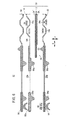
図4は、本発明の第2の実施形態に係る燃料電池60の一部断面説明図である。なお、第1の実施形態に係る燃料電池10と同一の構成要素には同一の参照符号を付して、その詳細な説明は省略する。また、以下に説明する第3〜第5の実施形態においても同様に、その詳細な説明は省略する。
FIG. 4 is a partial cross-sectional explanatory view of a
燃料電池60は、第1金属セパレータ14の外周端部を周回して第1シール部材62が、例えば、射出成形等により一体化される。この第1シール部材62は、面14aに一体化される突部64aを備え、この突部64aは、電解質膜・電極構造体12を周回して酸化剤ガス流路32をシールする。第1シール部材62は、面14bに突部64aに対応して突部64bが一体化される。
The
第2金属セパレータ16の外周端部を周回して第2シール部材66が、例えば、射出成形等により一体化される。この第2シール部材66は、面16aに一体化される突部68と第1及び第2吸着盤(吸盤構造)70、72とを備える。
The
突部68は、電解質膜・電極構造体12を構成する固体高分子電解質膜26の外周縁部に密着するとともに、第1吸着盤70は、前記固体高分子電解質膜26の外周縁部に対向して複数配置される。第2吸着盤72は、第1金属セパレータ14の第1シール部材62に対向して複数配置される。
The
このように構成される第2の実施形態では、第2金属セパレータ16が図示しない配置台の所定の位置に配置された後、電解質膜・電極構造体12が前記第2金属セパレータ16に位置決めされる。
In the second embodiment configured as described above, after the
この状態で、電解質膜・電極構造体12と第2金属セパレータ16とが互いに押圧されると、前記第2金属セパレータ16に設けられている第2シール部材66の第1吸着盤70が、前記電解質膜・電極構造体12の固体高分子電解質膜26の外周縁部に押し付けられる。このため、第1吸着盤70は、変形して固体高分子電解質膜26を吸着保持し、第2金属セパレータ16と電解質膜・電極構造体12とが一体化される。
In this state, when the electrolyte membrane /
次いで、第1金属セパレータ14が電解質膜・電極構造体12上に位置決めされた後、この第1金属セパレータ14が第2金属セパレータ16に向かって押圧される。第2金属セパレータ16に設けられている第2シール部材66の第2吸着盤72は、第1金属セパレータ14に設けられている第1シール部材62に当接して変形する。これにより、第2吸着盤72がこの第1金属セパレータ14を吸着し、第1及び第2金属セパレータ14、16同士が一体化される。
Next, after the
このように、第2の実施形態では、先ず、第2金属セパレータ16上に電解質膜・電極構造体12を配置して押圧力を付与する。次に、電解質膜・電極構造体12に第1金属セパレータ14を載置して、前記第1金属セパレータ14に押圧力を付与するだけで、第1及び第2吸着盤70、72の吸引作用下に、燃料電池60全体が一体化される。
As described above, in the second embodiment, first, the electrolyte membrane /
このため、燃料電池60の組み立て作業が簡素化して、自動化が一層容易に図られるとともに、前記燃料電池60の保持機能が一層確実に遂行されるという効果が得られる。
For this reason, the assembly operation of the
図5は、本発明の第3の実施形態に係る燃料電池80の一部断面説明図である。この燃料電池80は、電解質膜・電極構造体12の外周端部に一体化される部材82を備える。部材82には、第2金属セパレータ16に向かって突出する吸着盤(吸盤構造)84が一体的に設けられる。
FIG. 5 is a partial cross-sectional explanatory view of a
このように構成される第3の実施形態では、上記の第2の実施形態と同様に、第2金属セパレータ16に電解質膜・電極構造体12が位置合わせされた状態で、押圧力が付与される。このため、電解質膜・電極構造体12に一体化された部材82の吸着盤84が、第2金属セパレータ16の第2シール部材48に接触する。
In the third embodiment configured as described above, a pressing force is applied in a state in which the electrolyte membrane /
従って、吸着盤84の吸引作用下に、電解質膜・電極構造体12が第2金属セパレータ16に保持され、さらに第1金属セパレータ14が前記電解質膜・電極構造体12に積層されて押圧力が付与される。これによって、吸着盤44の吸引作用下に、第1金属セパレータ14と第2金属セパレータ16とが一体化され、燃料電池80全体が一体的に保持可能になる。
Therefore, the electrolyte membrane /
図6は、本発明の第4の実施形態に係る燃料電池90が積層された燃料電池スタック92の一部断面説明図である。
FIG. 6 is a partial cross-sectional explanatory view of a
この燃料電池90では、第1金属セパレータ14に第1シール部材62aが一体化されるとともに、第2金属セパレータ16に第2シール部材94が一体化される。第1シール部材62aは、面14aに突部64aを一体化する一方、第2シール部材94は、電解質膜・電極構造体12とは反対の面16bに、突部64aと吸着盤(吸盤構造)96とが設けられる。
In the
このように構成される第4の実施形態では、一方の燃料電池90を構成する第2金属セパレータ16が、他方の燃料電池90を構成する第1金属セパレータ14に重ね合わされる。このため、第2金属セパレータ16に設けられている第2シール部材94の吸着盤96が、第1金属セパレータ14に設けられている第1シール部材62aに接触する。
In the fourth embodiment configured as described above, the
これにより、吸着盤96は、変形して第1シール部材62aの面を吸着し、積層される各燃料電池90の第1及び第2金属セパレータ14、16同士が一体化される。従って、燃料電池スタック92の組み立て作業が容易且つ確実に遂行されるという効果が得られる。
Thereby, the
図7は、本発明の第5の実施形態に係る燃料電池100を積層した燃料電池スタック102の一部断面説明図である。
FIG. 7 is a partial cross-sectional explanatory view of the
燃料電池100では、第1金属セパレータ14に第1シール部材104が一体化されるとともに、第2金属セパレータ16に第2シール部材106が一体化される。
In the
第1シール部材104は、突部42bが設けられる面14bに吸着盤(吸盤構造)108が一体的に設けられる。第2シール部材106は、突部50が設けられる面16aにシール用の突起110が一体的に設けられている。電解質膜・電極構造体12の外周部には、吸着盤84を一体的に設けた部材82が一体化されている。
The
このように構成される第5の実施形態では、第4の実施形態と同様に、一方の燃料電池100を構成する第1金属セパレータ14と、他方の燃料電池100を構成する第2金属セパレータ16とが、吸着盤108の吸引作用下に一体的に保持されるため、燃料電池スタック102の組み付け作業が効率的に遂行されるという利点が得られる。
In the fifth embodiment configured as described above, similarly to the fourth embodiment, the
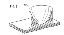
なお、第1〜第5の実施形態では、吸着盤44、70、72、84、96及び108が首部46aと湾曲するカップ部46bとを一対的に備えているが、これに限定されるものではない。例えば、図8に示す吸着盤(吸盤構造)120は、シール部材122に一体化されるとともに、略円筒状に構成されている。従って、シール部材122に吸着盤120を一体成形するための金型構成が簡素化するという効果がある。
In the first to fifth embodiments, the
また、図9に示す吸着盤(吸盤構造)124は、シール部材126に一体成形されるとともに、首部を用いることがなく、カップ部128が直接前記シール部材126に一体成形されている。この吸着盤124では、図示しない被吸着物に押し付ける際に、該吸着盤124自体の反力がシール部材126の平坦面まで上昇し難いという利点がある。
Further, the suction cup (suction cup structure) 124 shown in FIG. 9 is integrally formed with the
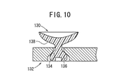
一方、第1〜第5の実施形態では、吸着盤44、70、72、84、96及び108が射出成形によって第1シール部材40と共に第1金属セパレータ14に一体化されているが、これに限定されるものではない。例えば、図10に示す吸着盤(吸盤構造)130は、セパレータ132に嵌めこみ等によって取り付けられている。
On the other hand, in the first to fifth embodiments, the
このセパレータ132には、一部にテーパを有する取り付け穴134が形成される。一方、吸着盤130は、取り付け穴134に嵌合する球状部136と、湾曲形状のカップ部138とを弾性変形可能なゴム材等により一体成形される。そこで、吸着盤130の球状部136を、取り付け穴134の小径側から押し込むと、この球状部136が前記取り付け穴134のテーパ部に係合する。これにより、吸着盤130はセパレータ132に取り付けられる。
A mounting
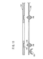
また、図11に示すように、予め成形されたシール部材140を用意し、このシール部材140がセパレータ142に設けられたシール溝144を介して、前記セパレータ142に取り付けられる構造が採用可能である。
In addition, as shown in FIG. 11, it is possible to employ a structure in which a
シール部材140には、セパレータ142のシール溝144に嵌合するシール部146と、シール用突部148と、吸着盤(吸盤構造)150とが一体成形されている。従って、吸着盤150が一体成形されたシール部材140を予め成形しておき、このシール部材140をセパレータ142に取り付けるだけで、前記セパレータ142に前記吸着盤150が保持される。
The
10、60、80、90、100…燃料電池
12…電解質膜・電極構造体 14、16…金属セパレータ
14a、14b、16a、16b…面 20a…酸化剤ガス入口連通孔
20b…酸化剤ガス出口連通孔 22a…冷却媒体入口連通孔
22b…冷却媒体出口連通孔 24a…燃料ガス入口連通孔
24b…燃料ガス出口連通孔 26…固体高分子電解質膜
28…アノード側電極 30…カソード側電極
32…酸化剤ガス流路 34…燃料ガス流路
36…冷却媒体流路
40、48、62、62a、66、82、94、104、106、122、126、140…シール部材
42a、42b、50、64a、64b、68、148…突部
44、70、72、84、96、108、120、124、130、150…吸着盤
46a…首部 46b…カップ部
110…突起
DESCRIPTION OF
Claims (3)
少なくとも一方のセパレータ又は前記電解質・電極構造体には、2枚のセパレータ同士又は該セパレータと該電解質・電極構造体とを互いに保持するための弾性変形可能な吸盤構造が設けられることを特徴とする燃料電池。 A fuel cell configured by sandwiching an electrolyte / electrode structure provided with a pair of electrodes on both sides of an electrolyte with a pair of separators,
At least one separator or the electrolyte / electrode structure is provided with an elastically deformable suction cup structure for holding two separators or the separator and the electrolyte / electrode structure together. Fuel cell.
2. The fuel cell according to claim 1, wherein the suction cup structure is attached to at least one of the separator and the electrolyte / electrode structure.
Priority Applications (1)
| Application Number | Priority Date | Filing Date | Title |
|---|---|---|---|
| JP2003376379A JP2005142000A (en) | 2003-11-06 | 2003-11-06 | Fuel cell |
Applications Claiming Priority (1)
| Application Number | Priority Date | Filing Date | Title |
|---|---|---|---|
| JP2003376379A JP2005142000A (en) | 2003-11-06 | 2003-11-06 | Fuel cell |
Publications (1)
| Publication Number | Publication Date |
|---|---|
| JP2005142000A true JP2005142000A (en) | 2005-06-02 |
Family
ID=34687439
Family Applications (1)
| Application Number | Title | Priority Date | Filing Date |
|---|---|---|---|
| JP2003376379A Withdrawn JP2005142000A (en) | 2003-11-06 | 2003-11-06 | Fuel cell |
Country Status (1)
| Country | Link |
|---|---|
| JP (1) | JP2005142000A (en) |
Cited By (6)
| Publication number | Priority date | Publication date | Assignee | Title |
|---|---|---|---|---|
| JP2008071506A (en) * | 2006-09-12 | 2008-03-27 | Matsushita Electric Ind Co Ltd | Polymer electrolyte fuel cell |
| JP2008097899A (en) * | 2006-10-10 | 2008-04-24 | Nok Corp | Gasket for fuel cell |
| DE112007000024B4 (en) * | 2006-04-21 | 2009-04-16 | Matsushita Electric Industrial Co., Ltd., Kadoma-shi | Solid-state polymer type fuel cell and fuel cell stack |
| JP2009099424A (en) * | 2007-10-17 | 2009-05-07 | Equos Research Co Ltd | Gasket member and fuel cell stack |
| JP2015103307A (en) * | 2013-11-21 | 2015-06-04 | 日産自動車株式会社 | Fuel cell and manufacturing method thereof |
| DE102022114702A1 (en) | 2022-06-10 | 2023-12-21 | Ekpo Fuel Cell Technologies Gmbh | Electrochemical device and method for assembling a stack of electrochemical units of an electrochemical device |
-
2003
- 2003-11-06 JP JP2003376379A patent/JP2005142000A/en not_active Withdrawn
Cited By (7)
| Publication number | Priority date | Publication date | Assignee | Title |
|---|---|---|---|---|
| DE112007000024B4 (en) * | 2006-04-21 | 2009-04-16 | Matsushita Electric Industrial Co., Ltd., Kadoma-shi | Solid-state polymer type fuel cell and fuel cell stack |
| US7541108B2 (en) | 2006-04-21 | 2009-06-02 | Panasonic Corporation | Solid polymer fuel cell |
| JP2008071506A (en) * | 2006-09-12 | 2008-03-27 | Matsushita Electric Ind Co Ltd | Polymer electrolyte fuel cell |
| JP2008097899A (en) * | 2006-10-10 | 2008-04-24 | Nok Corp | Gasket for fuel cell |
| JP2009099424A (en) * | 2007-10-17 | 2009-05-07 | Equos Research Co Ltd | Gasket member and fuel cell stack |
| JP2015103307A (en) * | 2013-11-21 | 2015-06-04 | 日産自動車株式会社 | Fuel cell and manufacturing method thereof |
| DE102022114702A1 (en) | 2022-06-10 | 2023-12-21 | Ekpo Fuel Cell Technologies Gmbh | Electrochemical device and method for assembling a stack of electrochemical units of an electrochemical device |
Similar Documents
| Publication | Publication Date | Title |
|---|---|---|
| EP2347464B1 (en) | Fuel cell stack | |
| US9194048B2 (en) | Electrochemical device | |
| US10026986B2 (en) | Fuel cell stack | |
| US20050019643A1 (en) | Fuel cell stack | |
| JP2017139218A (en) | Manufacturing method of fuel cell stack and manufacturing method of metal separator for fuel cell | |
| JP2006049129A (en) | Fuel cell stack | |
| US9673458B2 (en) | Fuel cell | |
| CN114551957B (en) | Fuel cell stack and method for manufacturing fuel cell stack | |
| JP4165876B2 (en) | Fuel cell stack | |
| JP4118123B2 (en) | Fuel cell stack | |
| JP4174022B2 (en) | Fuel cell stack | |
| JP5105742B2 (en) | Fuel cell stack | |
| JP2006236611A (en) | Fuel cell stack | |
| EP2999040A1 (en) | Apparatus and method for producing fuel cell separator assembly | |
| JP5236874B2 (en) | Fuel cell stack | |
| JP5879227B2 (en) | Fuel cell stack | |
| JP4789478B2 (en) | Fuel cell stack and assembly method thereof | |
| JP2005251635A (en) | Fuel cell stack | |
| JP4911951B2 (en) | Fuel cell and manufacturing method thereof | |
| JP2005243286A (en) | Fuel cell stack | |
| JP2005268080A (en) | Fuel cell stack | |
| JP5378049B2 (en) | Fuel cell stack | |
| JP2011165570A (en) | Fuel cell | |
| JP2008066178A (en) | Fuel cell stack | |
| JP2005243282A (en) | Assembly method of fuel cell stack |
Legal Events
| Date | Code | Title | Description |
|---|---|---|---|
| A621 | Written request for application examination |
Free format text: JAPANESE INTERMEDIATE CODE: A621 Effective date: 20051202 |
|
| A761 | Written withdrawal of application |
Free format text: JAPANESE INTERMEDIATE CODE: A761 Effective date: 20070807 |