JP2005149794A - Electrode for battery and battery - Google Patents
Electrode for battery and battery Download PDFInfo
- Publication number
- JP2005149794A JP2005149794A JP2003382556A JP2003382556A JP2005149794A JP 2005149794 A JP2005149794 A JP 2005149794A JP 2003382556 A JP2003382556 A JP 2003382556A JP 2003382556 A JP2003382556 A JP 2003382556A JP 2005149794 A JP2005149794 A JP 2005149794A
- Authority
- JP
- Japan
- Prior art keywords
- electrode
- battery
- resistance
- fuse
- current
- Prior art date
- Legal status (The legal status is an assumption and is not a legal conclusion. Google has not performed a legal analysis and makes no representation as to the accuracy of the status listed.)
- Granted
Links
- 229910052751 metal Inorganic materials 0.000 claims description 5
- 239000002184 metal Substances 0.000 claims description 5
- 230000020169 heat generation Effects 0.000 abstract description 18
- 239000000155 melt Substances 0.000 abstract description 4
- 230000004048 modification Effects 0.000 description 18
- 238000012986 modification Methods 0.000 description 18
- WHXSMMKQMYFTQS-UHFFFAOYSA-N Lithium Chemical compound [Li] WHXSMMKQMYFTQS-UHFFFAOYSA-N 0.000 description 9
- 229910052744 lithium Inorganic materials 0.000 description 9
- 238000004519 manufacturing process Methods 0.000 description 4
- 238000007789 sealing Methods 0.000 description 4
- 206010037660 Pyrexia Diseases 0.000 description 3
- 239000011248 coating agent Substances 0.000 description 3
- 238000000576 coating method Methods 0.000 description 3
- 230000000694 effects Effects 0.000 description 2
- 238000002955 isolation Methods 0.000 description 2
- 238000009782 nail-penetration test Methods 0.000 description 2
- 239000011255 nonaqueous electrolyte Substances 0.000 description 2
- 229910052782 aluminium Inorganic materials 0.000 description 1
- XAGFODPZIPBFFR-UHFFFAOYSA-N aluminium Chemical group [Al] XAGFODPZIPBFFR-UHFFFAOYSA-N 0.000 description 1
- 238000010586 diagram Methods 0.000 description 1
- 239000000463 material Substances 0.000 description 1
- 238000002844 melting Methods 0.000 description 1
- 230000008018 melting Effects 0.000 description 1
- 238000000034 method Methods 0.000 description 1
- 229920006254 polymer film Polymers 0.000 description 1
- 229910001220 stainless steel Inorganic materials 0.000 description 1
- 239000010935 stainless steel Substances 0.000 description 1
Images








Classifications
-
- Y—GENERAL TAGGING OF NEW TECHNOLOGICAL DEVELOPMENTS; GENERAL TAGGING OF CROSS-SECTIONAL TECHNOLOGIES SPANNING OVER SEVERAL SECTIONS OF THE IPC; TECHNICAL SUBJECTS COVERED BY FORMER USPC CROSS-REFERENCE ART COLLECTIONS [XRACs] AND DIGESTS
- Y02—TECHNOLOGIES OR APPLICATIONS FOR MITIGATION OR ADAPTATION AGAINST CLIMATE CHANGE
- Y02E—REDUCTION OF GREENHOUSE GAS [GHG] EMISSIONS, RELATED TO ENERGY GENERATION, TRANSMISSION OR DISTRIBUTION
- Y02E60/00—Enabling technologies; Technologies with a potential or indirect contribution to GHG emissions mitigation
- Y02E60/10—Energy storage using batteries
-
- Y—GENERAL TAGGING OF NEW TECHNOLOGICAL DEVELOPMENTS; GENERAL TAGGING OF CROSS-SECTIONAL TECHNOLOGIES SPANNING OVER SEVERAL SECTIONS OF THE IPC; TECHNICAL SUBJECTS COVERED BY FORMER USPC CROSS-REFERENCE ART COLLECTIONS [XRACs] AND DIGESTS
- Y02—TECHNOLOGIES OR APPLICATIONS FOR MITIGATION OR ADAPTATION AGAINST CLIMATE CHANGE
- Y02P—CLIMATE CHANGE MITIGATION TECHNOLOGIES IN THE PRODUCTION OR PROCESSING OF GOODS
- Y02P70/00—Climate change mitigation technologies in the production process for final industrial or consumer products
- Y02P70/50—Manufacturing or production processes characterised by the final manufactured product
Landscapes
- Secondary Cells (AREA)
- Connection Of Batteries Or Terminals (AREA)
- Battery Electrode And Active Subsutance (AREA)
Abstract
Description
本発明は、リチウム電池等、電極を複数枚積層して構成される電池、および、該電池に用いられる電極に関する。 The present invention relates to a battery configured by stacking a plurality of electrodes, such as a lithium battery, and an electrode used in the battery.
図16に、従来のリチウム二次電池の一例を示す。このリチウム二次電池1は、いわゆる角型と呼ばれるもので、複数の正極電極(電極)2…と、負極電極(電極)3…と、これら正極電極2…及び負極電極3…の間にそれぞれ配置されたセパレータ4…と、非水電解液とを主体として構成されている。
正極電極2…、負極電極3…及びセパレータ4…並びに非水電解液は、ステンレス等からなる電池ケース5に収納されている。そして電池ケース5の開口部には封口体6が取り付けられている。
FIG. 16 shows an example of a conventional lithium secondary battery. The lithium
The positive electrode 2..., The
電池ケース5内においては、正極電極2…、セパレータ4…及び負極電極3…が交互に複数重ね合わされて収納されている。
正極電極2…の一端には正極タブ部12a…が形成され、正極タブ部12a…の上部には該正極タブ部12a…を連結する正極リード12bが取り付けられている。
そして、正極リード12bの上部には、封口体6を貫通する正極端子7が取り付けられている。
また、負極電極3…の一端には負極タブ部13a…が形成され、負極タブ部13a…の上部には該負極タブ部13a…を連結する負極リード13bが取り付けられている。
そして、負極リード13bの上部には、封口体6を貫通する負極端子8が取り付けられている。
上記構成によって、正極端子7及び負極端子8により、正極電極2…及び負極電極3…からの電流を取り出せるように構成されている。
また、封口体6のほぼ中央には安全弁9が設けられている。
A positive
And the
Further,
And the
With the above configuration, the
A
このようなリチウム二次電池において、大型化、大容量化に伴い、内部短絡発生時に短絡部に流れる電流・時間が大きく、長くなる傾向がある。
電池容量が数Whの小型リチウム電池(18650型)では発熱は80℃から100℃程度であるが,数百Whの大型リチウム二次電池の場合、強制的に内部短絡させると、数千Aの電流が流れ、400℃以上の温度上昇が生ずる。
局所的な短絡電流のレベルが所定の閾値を越えると、ジュール発熱による局所的な温度上昇によりさらに発熱反応が進む熱暴走が進行する可能性があるため、短絡電流の局所集中を抑えることが電池の信頼性を向上させることにつながる。
In such a lithium secondary battery, with an increase in size and capacity, the current and time flowing through the short circuit portion when an internal short circuit occurs tends to be large and long.
In a small lithium battery (18650 type) with a battery capacity of several Wh, the heat generation is about 80 ° C. to 100 ° C. However, in the case of a large lithium secondary battery of several hundred Wh, if the internal short circuit is forced, several thousand A A current flows and a temperature rise of 400 ° C. or more occurs.
If the local short-circuit current level exceeds a predetermined threshold, there is a possibility that a thermal runaway in which an exothermic reaction further progresses due to a local temperature rise due to Joule heat generation. Leading to improved reliability.
本発明は上記事情に鑑みて成されたものであり、短絡時の短絡電流の局所集中を抑えることができる電池用電極および電池を提供することを目的とする。 The present invention has been made in view of the above circumstances, and an object thereof is to provide a battery electrode and a battery that can suppress local concentration of a short-circuit current at the time of a short circuit.
本発明においては上記の課題を解決するために以下の手段を採用した。
請求項1に記載の発明は、複数枚積層されて電池を構成する電池用電極において、該電極内に、電流経路を制限する抵抗部が設けられていることを特徴とする。
請求項2に記載の発明は、請求項1に記載の電池用電極において、電極本体と、該電極本体の一端に設けられ電池端子とつながるタブ部とを備え、前記電極本体とタブ部との少なくともいずれか一方に、前記抵抗部が設けられていることを特徴とする。
請求項3に記載の発明は、請求項2に記載の電池用電極において、前記電極本体とタブ部との両方に前記抵抗部が設けられていることを特徴とする。
請求項4に記載の発明は、請求項1から3いずれかに記載の電池用電極において、前記抵抗部は、電極に入れられた切り込みにより限界された電極の幅狭部であることを特徴とする。
請求項5に記載の発明は、請求項4に記載の電池用電極において、前記電極が、前記切り込みによって複数の幅の狭い極板区画に分割され、各極板区画が前記幅狭部によって互いに連結した状態となっていることにより電流経路が長くとられていることを特徴とする。
請求項6に記載の発明は、請求項1から5いずれかに記載の電池用電極において、絶縁層の両面のそれぞれに複数の孔を備えた金属層が設けられ、前記孔の周囲が前記抵抗部となっていることを特徴とする。
In the present invention, the following means are adopted in order to solve the above problems.
The invention described in
According to a second aspect of the present invention, in the battery electrode according to the first aspect, the electrode main body and a tab portion provided at one end of the electrode main body and connected to the battery terminal are provided, and the electrode main body and the tab portion At least one of the resistance portions is provided.
According to a third aspect of the present invention, in the battery electrode according to the second aspect, the resistance portion is provided on both the electrode body and the tab portion.
According to a fourth aspect of the present invention, in the battery electrode according to any one of the first to third aspects, the resistance portion is a narrow portion of the electrode limited by a notch formed in the electrode. To do.
According to a fifth aspect of the present invention, in the battery electrode according to the fourth aspect, the electrode is divided into a plurality of narrow electrode plate sections by the notches, and each electrode plate section is separated from each other by the narrow portion. The current path is long due to the connected state.
According to a sixth aspect of the present invention, in the battery electrode according to any one of the first to fifth aspects, a metal layer having a plurality of holes is provided on each of both surfaces of the insulating layer, and the periphery of the hole is the resistance. It is characterized by being part.
本発明の概略を図15に示す。
図15(a)は従来例であって、正極と負極とを一組とする電極群が並列に接続され、一つの電池を構成している。
ある部分で抵抗RS(≒0Ω)の短絡が発生すると、電極の内部抵抗Riに短絡電流がながれる。内部抵抗Riは小さいため大電流Iが流れ、電流の二乗に比例した発熱が発生する。
図15(b)のように、電極内に抵抗Rhを設けると、短絡時に流れる電流が抑えられ(電流I’<I)、その結果温度上昇速度は従来よりも低下し、発熱速度が放熱速度を下回ると、熱暴走が抑えられる。
すなわち、本発明のように電極内に抵抗部を設けることにより、上記のように短絡時に局所的に大電流が流れることを防止し、発熱を抑える。
さらに、電流の経路を細く長くし、電流経路抵抗を大きくすることが有効であることもわかっている。
また、電極本体とタブ部の両方に抵抗部を設ければ、電極本体またはタブ部のいずれか一方に抵抗部を設ける場合よりも、全体の抵抗値の合計を抑えつつ非常に効果的に発熱を抑制できることもわかった。
An outline of the present invention is shown in FIG.
FIG. 15A shows a conventional example, in which a group of electrodes each having a positive electrode and a negative electrode are connected in parallel to form one battery.
When a short circuit of the resistance R S (≈0Ω) occurs in a certain portion, a short circuit current flows through the internal resistance R i of the electrode. Since the internal resistance R i is small, a large current I flows and heat is generated in proportion to the square of the current.
When a resistor Rh is provided in the electrode as shown in FIG. 15 (b), the current flowing at the time of short-circuiting is suppressed (current I ′ <I). Below the speed, thermal runaway is suppressed.
That is, by providing a resistance portion in the electrode as in the present invention, it is possible to prevent a large current from flowing locally at the time of a short circuit as described above and suppress heat generation.
Furthermore, it has been found that it is effective to increase the current path resistance by narrowing and extending the current path.
Also, if resistance parts are provided on both the electrode body and the tab part, heat is generated more effectively while suppressing the total resistance value than when a resistance part is provided on either the electrode body or the tab part. It was also found that can be suppressed.
請求項7に記載の発明は、請求項1から6のいずれかに記載の電池用電極において、前記抵抗部は、短絡電流に起因する熱により溶解することを特徴とする。 A seventh aspect of the present invention is the battery electrode according to any one of the first to sixth aspects, wherein the resistance portion is dissolved by heat caused by a short-circuit current.
本発明においては、抵抗部がヒューズとなって溶解することにより、短絡部分を電気的に隔離し、短絡電流を遮断することでそれ以上の発熱を防ぐ。例えば電極の材質がアルミニウムであれば、融点は約660℃であるから、短絡時に流れる電流によって抵抗部がこの温度を超えるように抵抗部のサイズを決める。
電極またはタブ部に抵抗部が複数設けられている場合、そのうちの一部が熱により溶解することとしてもよい。この場合溶解した抵抗部により短絡部分が電気的に隔離される、あるいは,電流経路が制限されることで流れる短絡電流を抑える。
In the present invention, when the resistance portion melts as a fuse, the short-circuit portion is electrically isolated and the short-circuit current is interrupted to prevent further heat generation. For example, when the material of the electrode is aluminum, the melting point is about 660 ° C., so the size of the resistance portion is determined so that the resistance portion exceeds this temperature by the current flowing at the time of short circuit.
When a plurality of resistance portions are provided on the electrode or the tab portion, some of them may be melted by heat. In this case, the short-circuit current is suppressed by electrically isolating the short-circuit portion by the dissolved resistance portion or by restricting the current path.
請求項8に記載の発明は、請求項1から7いずれかに記載の電池用電極において、前記電極がセパレータに融着されていることを特徴とする。
The invention according to
この発明においては切り込みに沿って電極が折れてしまう等の製造上の不都合が解消され、電極の取扱性が向上する。 In the present invention, manufacturing inconveniences such as breaking of the electrode along the notch are eliminated, and the handleability of the electrode is improved.
請求項9に記載の発明は、電極を複数枚積層してなる電池において、前記電極は請求項1から8のいずれかに記載の電極であることを特徴とする。
The invention according to
本発明によれば、電極が短絡した場合に、抵抗部によって短絡電流が抑えられ、または抵抗部が溶解して短絡部が電気的に隔離されることで、電池の熱暴走を防止し、より信頼性の高い電池とすることができる。 According to the present invention, when the electrode is short-circuited, the short-circuit current is suppressed by the resistance portion, or the resistance portion is dissolved and the short-circuit portion is electrically isolated, thereby preventing thermal runaway of the battery. A battery with high reliability can be obtained.
本発明においては以下の効果を得ることができる。
電極内またはタブ部に抵抗部を設けることにより、短絡時に大電流が流れることを防止し、発熱を抑える。また、抵抗部を熱により溶解するヒューズとすることで、短絡部分が電気的に隔離される。したがってこのような電極を電池に採用することで、電池の熱暴走を防止し、より信頼性の高い電池とすることができる。
さらに、電極本体とタブ部の両方に抵抗部を設けることにより、非常に効果的に発熱を抑制できる。
In the present invention, the following effects can be obtained.
By providing a resistance portion in the electrode or in the tab portion, a large current is prevented from flowing during a short circuit, and heat generation is suppressed. Moreover, a short circuit part is electrically isolated by making a resistance part into the fuse which melt | dissolves with a heat | fever. Therefore, by adopting such an electrode for a battery, thermal runaway of the battery can be prevented and a battery with higher reliability can be obtained.
Furthermore, heat generation can be suppressed very effectively by providing resistance portions on both the electrode body and the tab portion.
次に、本発明の実施形態について、図面を参照して説明する。
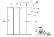
図1は本実施形態にかかる電極(正極、負極)15である。電極15は、電池端子とつながるタブ部15aと電極本体15bとを備え、電極本体15bの上縁端部から、電極本体15bより幅狭のタブ部15aが上方に突き出すように設けられている。
電極本体15bは、幅が狭く細長い複数の極板区画16,16…に分割され、各極板区画16,16…は互いに絶縁領域として隙間(切り込み)17を隔てた状態で、ヒューズ部(抵抗部)18によって連結されている。これにより電流経路が細く長くなった状態となっている。すなわち、極板区画16,16…自体の電流経路抵抗が従来より大きい状態となる。ヒューズ部18は隙間17により限界された幅の狭い電極領域であって、幅が狭いため電気抵抗となっている。この電極15を製造する際(電極層コーティング後が容易)に、各極板区画16が連結するようにヒューズ部18を残しつつ、隙間17を打ち抜く。これにより全体を一体成形する。
短絡時の例を図2に示す。図の符号19で短絡が発生した場合、極板区画16自体の電流経路抵抗により短絡回路の抵抗が増大する為、流れる電流が制限される。極板区画数を増やすことで、極板区画16自体の電流経路抵抗は増大し、ある程度まで抵抗が増大すると、短絡電流の減少に伴って最高到達温度が低下し、熱暴走が抑えられる。
また、区画上部にヒューズ部18a、18bを設けることで、ヒューズ部18が高電流により発熱し、溶解する。その結果短絡19が電気的に隔離され、隔離後の発熱が防止される。したがって熱暴走の発生が防止される。
Next, embodiments of the present invention will be described with reference to the drawings.
FIG. 1 shows an electrode (positive electrode, negative electrode) 15 according to this embodiment. The
The
An example of a short circuit is shown in FIG. When a short circuit occurs at the
Further, by providing the
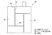
図3は変形例として示した電極(正極、負極)20である。電極20は、電池端子とつながるタブ部20aと電極本体20bとを備え、電極本体20bの上縁端部から、電極本体20bより幅狭のタブ部20aが上方に突き出すように設けられている。
電極本体20bは、複数の極板区画22,22,…が、互いに絶縁領域として隙間(切り込み)23を隔てた状態で、ヒューズ部(抵抗部)24によって連結されている。ヒューズ部24は隙間23により限界された幅の狭い電極領域であって、幅が狭いため電気抵抗となっている。この電極20を製造する際(電極層コーティング後が容易)に、各極板区画22が連結するようにヒューズ部24を残しつつ、格子状に隙間23を打ち抜く。これにより全体を一体成形する。
本変形例においても、短絡時には図2と同様にヒューズ部24に高電流が流れる。ヒューズ部24は電気抵抗であるから高電流により発熱し、溶解する。その結果短絡が電気的に隔離され、隔離後の発熱が防止される。したがって熱暴走の発生が防止される。
またヒューズ部24が溶解しない場合でも、抵抗としてヒューズ部24が電流経路を制限するため、流れる電流は従来より少ない。発熱は電流の二乗に比例するため、温度上昇速度はヒューズ部24が設けられていない従来例より遅い。したがって発生した熱は自然に放熱され、熱暴走が抑えられる。
FIG. 3 shows an electrode (positive electrode, negative electrode) 20 shown as a modification. The
In the
Also in this modification, a high current flows through the
Even when the
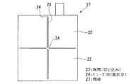
図4および図5に示したものは極板区画22の配置を異ならせた変形例(電極26,27)である。これらの例でも図3と同様の効果を得ることができる。図4の場合、隙間23が電極26の幅または高さ方向全体にわたって設けられていないから、製造時において電極26が隙間23に沿って折り曲がらず取り扱いがより容易である。
4 and FIG. 5 show modifications (
図6に示したものは、変形例としての電極28である。図の例では、電極は複数列のミシン目29により複数の極板区画30に分割されている。各ミシン目29は、隙間(切り込み)29aと極板区画30を連結するヒューズ部(抵抗部)29bとがそれぞれ交互に多数並んで構成されている。ヒューズ部29bは隙間29aにより限界された幅の狭い電極領域となっており、幅が狭いために電気抵抗となっている。本例においても、電極28を型抜きする際に、ミシン目29を電極28に打ち付ける。これにより全体を一体成形する。
FIG. 6 shows an
本電極においても、上記の例と同様に、短絡時にはヒューズ部29bが溶解し、短絡部が電気的に隔離され、過度の発熱が防止される。
またヒューズ部29bが溶解しない場合でも、抵抗としてヒューズ部29bが電流経路を制限するため、上記の例と同様に、温度上昇速度が抑制され、熱暴走が抑えられる。
Also in this electrode, similarly to the above example, the
Even when the
さらに、上記各例に対して、図7に示すように、電極にセパレータ31を融着させてもよい。これにより強度が増強され、隙間23やミシン目29等に沿って折れてしまう等の製造上の不都合が解消され、電極の取り扱い性が向上する。
Furthermore, for each of the above examples, as shown in FIG. 7, a
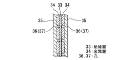
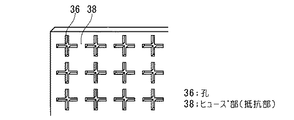
さらにまた、図8は他の電極の例であり、電極の断面図である。絶縁層(高分子フィルム)33の両面に金属層34が形成されている。さらに電極層35が塗工されている。金属層34は図9または図10に示すように、全体に孔36,37が設けられている。これら孔36,37の周囲がヒューズ部(抵抗部)38,39となる。
この例においても、短絡時にはヒューズ部38,39が溶解し、短絡部が電気的に隔離され、過度の発熱が防止される。またヒューズ部38,39が溶解しない場合でも、抵抗としてヒューズ部38,39が電流経路を制限するため、上記の例と同様に、温度上昇速度が抑制され、熱暴走が抑えられる。
なお、リチウム電池は電極が厚く、そのため複数の極板を貼り合わせて一枚の電極としなければならない。したがって全体に孔をあける本変形例より、上記の隙間23またはミシン目29を入れる工程の方がより容易に製造することができる。
Furthermore, FIG. 8 is an example of another electrode, and is a sectional view of the electrode. Metal layers 34 are formed on both surfaces of the insulating layer (polymer film) 33. Further, an
Also in this example, at the time of a short circuit, the
Note that the lithium battery has a thick electrode, and therefore, a plurality of electrode plates must be bonded to form a single electrode. Therefore, the process of putting the
さらに、図11の電極40のように、図3の電極20の変形例として電池端子とつながるタブ部40aから離れるほど隙間23の間隔を広くするようにしてもよい。図ではタブ部40aを基準として、電極本体40b上縁からもっとも近接した左右方向に延びる隙間23までの距離をL1,次の左右方向に延びる隙間23までの距離をL2,さらに電極本体40bの下縁までの距離をL3とした。これらの関係をL1<L2<L3とする。
本例のように構成するとタブ部40a近傍がより高い抵抗となる。隙間23およびヒューズ部24が設けられていない従来技術においては、タブ部40aに近いほど高電流が流れる。したがって本例では高電流が流れる場所に対して適切な抵抗部を設けたことで、効率よく高電流を抑えることができる。
同様の理由から、タブ部40aから離れるほどヒューズ部24の幅を広くとってもよい。
なお本変形例は図3の電極20のみならず、上記に説明した他の電極に対しても適用できるのはもちろんである。
Furthermore, like the
When configured as in this example, the vicinity of the
For the same reason, the width of the
Of course, the present modification can be applied not only to the
さらにまた、変形例として図12の電極41のように、タブ部41aにヒューズ部を設けてもよい。本電極41においては、タブ部41aは、幅が狭く細長い複数の極板区画42,42…に分割され、各極板区画42,42…は互いに絶縁領域として隙間(切り込み)42aを隔てた状態で、ヒューズ部(抵抗部)42bによって連結されている。これにより電流経路は細く長くなった状態となっている。ヒューズ部42bは隙間により限界された幅の狭い電極領域であって、幅が狭いため電気抵抗となっている。この電極41を製造する際(電極層コーティング後が容易)に、各極板区画42が連結するようにヒューズ部42bを残しつつ、隙間42aを打ち抜く。これにより全体を一体成形する。
本電極41においても、ヒューズ部42bの作用、および極板区画42の電流経路抵抗が大きいことにより、上記の各例と同様に短絡時の発熱を防止することができる。
Furthermore, as a modification, a fuse portion may be provided in the
Also in the
さらにまた、以下のように構成してもよい。図13の電極43のように電極本体43b側の、タブ部43aの近傍にタブ部43aを取り囲むように曲線に沿ったミシン目44を設ける。この場合、ミシン目42が曲線に沿っているため、折曲しにくく、取り扱いが容易となる。
なお、ミシン目44の詳細な構成については前記したミシン目29と同様であるから説明を省略する。
この電極43においても、ミシン目44が設けられていることによって短絡時の発熱を防止することができる。
Furthermore, you may comprise as follows. A
Note that the detailed configuration of the
Also in this
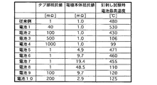
以上の各例では、タブ部のみ、または電極本体にのみ抵抗を設けている。さらに、タブ部と電極本体の両方に抵抗部を設けると、より効果的に発熱を抑えられる。300wh級の一般的なリチウム電池について、タブ部および電流経路の抵抗値を変えて釘刺し試験を行った場合の発熱を計測した。その結果を図14に示した。タブ部の抵抗としては図12の例、電極本体の抵抗として図1の例を用いた。
タブ部にのみヒューズ部を設けた場合には、タブ部の抵抗が500mΩ以上で106℃以下に発熱が抑えられ、また、電極本体にのみヒューズ部を設けた場合には48.5mΩ以上で110℃に発熱が抑えられた。一方、これらを組み合わせた場合、電池9および電池10のように、タブ部の抵抗が100mΩで電極本体の抵抗が9.7mΩ、または、タブ部の抵抗が200mΩで電極本体の抵抗が2.9mΩの場合に、最高温度がそれぞれ120℃、125℃と十分に低温になったことが確認された。
このように、タブ部と電極本体の双方にヒューズ部を設けると、高いエネルギー効率を維持したまま,信頼性の高い電池を構成することができる。
In each of the above examples, a resistor is provided only on the tab portion or only on the electrode body. Furthermore, if a resistance part is provided in both the tab part and the electrode body, heat generation can be suppressed more effectively. About the general lithium battery of 300wh class, the heat_generation | fever when the nail penetration test was done by changing the resistance value of a tab part and an electric current path was measured. The results are shown in FIG. The example of FIG. 12 was used as the resistance of the tab portion, and the example of FIG. 1 was used as the resistance of the electrode body.
When the fuse part is provided only in the tab part, the heat generation is suppressed to 106 ° C. or less when the resistance of the tab part is 500 mΩ or more, and when the fuse part is provided only in the electrode body, the resistance is 48.5 mΩ or more and 110 The exotherm was suppressed to ℃. On the other hand, when these are combined, like the
Thus, if a fuse part is provided in both a tab part and an electrode main body, a highly reliable battery can be comprised, maintaining high energy efficiency.
15 電極
15a タブ部
15b 電極本体
17 隙間(切り込み)
18 ヒューズ部(抵抗部)
20 電極
20a タブ部
20b 電極本体
23 隙間(切り込み)
24 ヒューズ部(抵抗部)
26,27,28 電極
29 ミシン目
29a 隙間(切り込み)
29b ヒューズ部(抵抗部)
31 セパレータ
33 絶縁層
34 金属層
36,37 孔
38,39 ヒューズ部(抵抗部)
40,41,43 電極
40a,41a,43a タブ部
42 極板区画
42a 隙間(切り込み)
42b ヒューズ部
44 ミシン目
15
18 Fuse part (resistor part)
20
24 Fuse part (resistor part)
26, 27, 28
29b Fuse part (resistor part)
31
40, 41, 43
Claims (9)
該電極内に、電流経路を制限する抵抗部が設けられていることを特徴とする電池用電極。 In the electrode for a battery constituting a battery by stacking a plurality of sheets,
A battery electrode, wherein a resistance portion for limiting a current path is provided in the electrode.
前記電極は請求項1から8のいずれかに記載の電極であることを特徴とする電池。
In a battery in which a plurality of electrodes are laminated,
The battery according to claim 1, wherein the electrode is an electrode according to claim 1.
Priority Applications (1)
| Application Number | Priority Date | Filing Date | Title |
|---|---|---|---|
| JP2003382556A JP4658467B2 (en) | 2003-11-12 | 2003-11-12 | Electrode for lithium secondary battery and lithium secondary battery |
Applications Claiming Priority (1)
| Application Number | Priority Date | Filing Date | Title |
|---|---|---|---|
| JP2003382556A JP4658467B2 (en) | 2003-11-12 | 2003-11-12 | Electrode for lithium secondary battery and lithium secondary battery |
Publications (2)
| Publication Number | Publication Date |
|---|---|
| JP2005149794A true JP2005149794A (en) | 2005-06-09 |
| JP4658467B2 JP4658467B2 (en) | 2011-03-23 |
Family
ID=34691597
Family Applications (1)
| Application Number | Title | Priority Date | Filing Date |
|---|---|---|---|
| JP2003382556A Expired - Fee Related JP4658467B2 (en) | 2003-11-12 | 2003-11-12 | Electrode for lithium secondary battery and lithium secondary battery |
Country Status (1)
| Country | Link |
|---|---|
| JP (1) | JP4658467B2 (en) |
Cited By (21)
| Publication number | Priority date | Publication date | Assignee | Title |
|---|---|---|---|---|
| JP2007142034A (en) * | 2005-11-16 | 2007-06-07 | Rohm Co Ltd | Electric double layer capacitor and its assembly |
| JP2009187675A (en) * | 2008-02-01 | 2009-08-20 | Sharp Corp | Multilayer secondary battery and manufacturing method thereof |
| JP2010165495A (en) * | 2009-01-14 | 2010-07-29 | Nec Tokin Corp | Laminated closed battery |
| KR100984576B1 (en) | 2007-05-15 | 2010-09-30 | 주식회사 엘지화학 | Electrode tab or lead wire having electrical resistivity controlled |
| JP2013505553A (en) * | 2009-09-28 | 2013-02-14 | エルジー・ケム・リミテッド | Secondary battery and manufacturing method thereof |
| CN104037381A (en) * | 2013-03-08 | 2014-09-10 | 三星Sdi株式会社 | Rechargeable battery |
| EP2338192A4 (en) * | 2008-10-20 | 2014-10-08 | Nissan Motor | BIPOLAR SECONDARY BATTERY, BATTERY PACK, AND VEHICLE EQUIPPED WITH SAME |
| KR20150030549A (en) * | 2013-09-12 | 2015-03-20 | 삼성에스디아이 주식회사 | Rechargeable battery |
| CN107256971A (en) * | 2017-05-23 | 2017-10-17 | 马鞍山活力电动科技有限公司 | A kind of Soft Roll ternary electrokinetic cell and preparation method thereof |
| CN107507959A (en) * | 2017-08-25 | 2017-12-22 | 江西优特汽车技术有限公司 | A kind of design method of pole piece of power battery |
| WO2018168286A1 (en) * | 2017-03-13 | 2018-09-20 | 株式会社豊田中央研究所 | Secondary battery and method for producing same |
| JP2019075278A (en) * | 2017-10-16 | 2019-05-16 | 株式会社豊田中央研究所 | Laminated structure, lithium secondary battery and method of manufacturing laminated structure |
| CN109920975A (en) * | 2019-04-01 | 2019-06-21 | 何志奇 | Regionally designed pole piece and its battery |
| CN113871570A (en) * | 2021-09-28 | 2021-12-31 | 三一技术装备有限公司 | Pole piece, roll up core and battery |
| JP2022079083A (en) * | 2020-11-16 | 2022-05-26 | 株式会社豊田中央研究所 | Electrode structure and power storage device |
| US20220367985A1 (en) * | 2020-10-20 | 2022-11-17 | Contemporary Amperex Technology Co., Limited | Electrode assembly, battery cell, battery, electrical apparatus, and manufacturing method and device |
| CN115548258A (en) * | 2022-11-02 | 2022-12-30 | 昆山东威科技股份有限公司 | Lithium battery cathode structure, battery core and lithium battery |
| JP2023528295A (en) * | 2020-06-04 | 2023-07-04 | 24エム・テクノロジーズ・インコーポレイテッド | Electrochemical cell with one or more segmented current collectors and method of making same |
| CN118983500A (en) * | 2024-08-01 | 2024-11-19 | 江苏睿恩新能源科技有限公司 | Cylindrical lithium ion battery and power-using device |
| JP2025507491A (en) * | 2022-05-11 | 2025-03-21 | ユーアンドエス エナジー インコーポレイテッド | Electrode current collector |
| US12555867B2 (en) | 2017-02-01 | 2026-02-17 | 24M Technologies, Inc. | Systems and methods for improving safety features in electrochemical cells |
Families Citing this family (3)
| Publication number | Priority date | Publication date | Assignee | Title |
|---|---|---|---|---|
| CN111108576B (en) | 2017-07-31 | 2023-03-07 | 24M技术公司 | Current Interrupting Devices Using Shape Memory Materials |
| US10854869B2 (en) | 2017-08-17 | 2020-12-01 | 24M Technologies, Inc. | Short-circuit protection of battery cells using fuses |
| DE102024110062A1 (en) * | 2024-04-11 | 2025-10-16 | Nils Krumm | Electrode with insulating areas to improve current flow within the electrode |
Citations (8)
| Publication number | Priority date | Publication date | Assignee | Title |
|---|---|---|---|---|
| JPH0850920A (en) * | 1994-08-08 | 1996-02-20 | Toyo Takasago Kandenchi Kk | Square lithium secondary battery |
| JPH10188946A (en) * | 1996-12-20 | 1998-07-21 | Toyo Takasago Kandenchi Kk | Prismatic battery with internal short-circuit protection device |
| JPH11265704A (en) * | 1998-03-17 | 1999-09-28 | Asahi Chem Ind Co Ltd | Nonaqueous battery and electrode terminal |
| JPH11345630A (en) * | 1998-06-02 | 1999-12-14 | Ngk Insulators Ltd | Lithium secondary battery |
| JP2001266894A (en) * | 2000-03-22 | 2001-09-28 | Sony Corp | Battery electrode and non-aqueous electrolyte battery using the same |
| JP2003197198A (en) * | 2001-12-26 | 2003-07-11 | Kakogawa Plastic Kk | Non-aqueous battery, electrode film and battery element constituting the same |
| JP2004253159A (en) * | 2003-02-18 | 2004-09-09 | Toshiba Corp | Non-aqueous electrolyte secondary battery |
| JP2004253356A (en) * | 2002-12-27 | 2004-09-09 | Matsushita Electric Ind Co Ltd | Current collector sheet for non-aqueous electrolyte secondary battery and non-aqueous electrolyte secondary battery |
-
2003
- 2003-11-12 JP JP2003382556A patent/JP4658467B2/en not_active Expired - Fee Related
Patent Citations (8)
| Publication number | Priority date | Publication date | Assignee | Title |
|---|---|---|---|---|
| JPH0850920A (en) * | 1994-08-08 | 1996-02-20 | Toyo Takasago Kandenchi Kk | Square lithium secondary battery |
| JPH10188946A (en) * | 1996-12-20 | 1998-07-21 | Toyo Takasago Kandenchi Kk | Prismatic battery with internal short-circuit protection device |
| JPH11265704A (en) * | 1998-03-17 | 1999-09-28 | Asahi Chem Ind Co Ltd | Nonaqueous battery and electrode terminal |
| JPH11345630A (en) * | 1998-06-02 | 1999-12-14 | Ngk Insulators Ltd | Lithium secondary battery |
| JP2001266894A (en) * | 2000-03-22 | 2001-09-28 | Sony Corp | Battery electrode and non-aqueous electrolyte battery using the same |
| JP2003197198A (en) * | 2001-12-26 | 2003-07-11 | Kakogawa Plastic Kk | Non-aqueous battery, electrode film and battery element constituting the same |
| JP2004253356A (en) * | 2002-12-27 | 2004-09-09 | Matsushita Electric Ind Co Ltd | Current collector sheet for non-aqueous electrolyte secondary battery and non-aqueous electrolyte secondary battery |
| JP2004253159A (en) * | 2003-02-18 | 2004-09-09 | Toshiba Corp | Non-aqueous electrolyte secondary battery |
Cited By (28)
| Publication number | Priority date | Publication date | Assignee | Title |
|---|---|---|---|---|
| JP2007142034A (en) * | 2005-11-16 | 2007-06-07 | Rohm Co Ltd | Electric double layer capacitor and its assembly |
| KR100984576B1 (en) | 2007-05-15 | 2010-09-30 | 주식회사 엘지화학 | Electrode tab or lead wire having electrical resistivity controlled |
| JP2009187675A (en) * | 2008-02-01 | 2009-08-20 | Sharp Corp | Multilayer secondary battery and manufacturing method thereof |
| EP2338192A4 (en) * | 2008-10-20 | 2014-10-08 | Nissan Motor | BIPOLAR SECONDARY BATTERY, BATTERY PACK, AND VEHICLE EQUIPPED WITH SAME |
| JP2010165495A (en) * | 2009-01-14 | 2010-07-29 | Nec Tokin Corp | Laminated closed battery |
| JP2013505553A (en) * | 2009-09-28 | 2013-02-14 | エルジー・ケム・リミテッド | Secondary battery and manufacturing method thereof |
| CN104037381A (en) * | 2013-03-08 | 2014-09-10 | 三星Sdi株式会社 | Rechargeable battery |
| KR101711988B1 (en) | 2013-09-12 | 2017-03-03 | 삼성에스디아이 주식회사 | Rechargeable battery |
| US9653721B2 (en) | 2013-09-12 | 2017-05-16 | Samsung Sdi Co., Ltd. | Rechargeable battery |
| KR20150030549A (en) * | 2013-09-12 | 2015-03-20 | 삼성에스디아이 주식회사 | Rechargeable battery |
| US12555867B2 (en) | 2017-02-01 | 2026-02-17 | 24M Technologies, Inc. | Systems and methods for improving safety features in electrochemical cells |
| WO2018168286A1 (en) * | 2017-03-13 | 2018-09-20 | 株式会社豊田中央研究所 | Secondary battery and method for producing same |
| US11171389B2 (en) | 2017-03-13 | 2021-11-09 | Kabushiki Kaisha Toyota Chuo Kenkyusho | Secondary battery and method for producing the same |
| CN107256971A (en) * | 2017-05-23 | 2017-10-17 | 马鞍山活力电动科技有限公司 | A kind of Soft Roll ternary electrokinetic cell and preparation method thereof |
| CN107507959A (en) * | 2017-08-25 | 2017-12-22 | 江西优特汽车技术有限公司 | A kind of design method of pole piece of power battery |
| JP7009903B2 (en) | 2017-10-16 | 2022-02-10 | 株式会社豊田中央研究所 | Method for manufacturing laminated structure, lithium secondary battery and laminated structure |
| JP2019075278A (en) * | 2017-10-16 | 2019-05-16 | 株式会社豊田中央研究所 | Laminated structure, lithium secondary battery and method of manufacturing laminated structure |
| CN109920975A (en) * | 2019-04-01 | 2019-06-21 | 何志奇 | Regionally designed pole piece and its battery |
| WO2020200155A1 (en) * | 2019-04-01 | 2020-10-08 | 何志奇 | Modularly designed pole pieces and battery thereof |
| JP2023528295A (en) * | 2020-06-04 | 2023-07-04 | 24エム・テクノロジーズ・インコーポレイテッド | Electrochemical cell with one or more segmented current collectors and method of making same |
| US20220367985A1 (en) * | 2020-10-20 | 2022-11-17 | Contemporary Amperex Technology Co., Limited | Electrode assembly, battery cell, battery, electrical apparatus, and manufacturing method and device |
| US12021269B2 (en) * | 2020-10-20 | 2024-06-25 | Contemporary Amperex Technology Co., Limited | Electrode assembly, battery cell, battery, electrical apparatus, and manufacturing method and device |
| JP2022079083A (en) * | 2020-11-16 | 2022-05-26 | 株式会社豊田中央研究所 | Electrode structure and power storage device |
| JP7505380B2 (en) | 2020-11-16 | 2024-06-25 | 株式会社豊田中央研究所 | Electrode structure and power storage device |
| CN113871570A (en) * | 2021-09-28 | 2021-12-31 | 三一技术装备有限公司 | Pole piece, roll up core and battery |
| JP2025507491A (en) * | 2022-05-11 | 2025-03-21 | ユーアンドエス エナジー インコーポレイテッド | Electrode current collector |
| CN115548258A (en) * | 2022-11-02 | 2022-12-30 | 昆山东威科技股份有限公司 | Lithium battery cathode structure, battery core and lithium battery |
| CN118983500A (en) * | 2024-08-01 | 2024-11-19 | 江苏睿恩新能源科技有限公司 | Cylindrical lithium ion battery and power-using device |
Also Published As
| Publication number | Publication date |
|---|---|
| JP4658467B2 (en) | 2011-03-23 |
Similar Documents
| Publication | Publication Date | Title |
|---|---|---|
| JP4658467B2 (en) | Electrode for lithium secondary battery and lithium secondary battery | |
| JP6498783B2 (en) | Pouch-type secondary battery including electrode lead with current limiting function | |
| JP6452059B2 (en) | Pouch-type secondary battery including electrode lead with current limiting function | |
| TWI596638B (en) | Protection components | |
| JP6437253B2 (en) | Protective element and mounting body | |
| JP5704645B2 (en) | Secondary battery | |
| KR20130085408A (en) | Protection element and method for producing protection element | |
| CN101479864A (en) | Secondary battery having electrode with self-cutting part self-destructed upon application of overcurrent | |
| JP5839061B2 (en) | Current interrupt device and power storage device including the same | |
| JP2018508968A (en) | Lithium secondary battery with improved safety using bimetal tabs | |
| TW201517105A (en) | Protective element | |
| JP2006040893A (en) | Secondary protection element for secondary battery | |
| JP2014123454A (en) | Power storage device | |
| JP6231324B2 (en) | Protection circuit board | |
| EP3279974A1 (en) | Electrode with an improved security behavior and battery cell comprising the same | |
| EP3279982B1 (en) | Current collector with an improved security behavior and battery cell comprising the same | |
| JP6254859B2 (en) | Breaking element, breaking element circuit, | |
| JP2024511328A (en) | Current collector for electrodes | |
| KR102173754B1 (en) | Secondary battery and the method of manufacturing the same | |
| KR102551377B1 (en) | Secondary battery | |
| KR20220111418A (en) | Lead-tab coupling structures and Secondary battery having the same | |
| KR100719731B1 (en) | Battery pack with alignment mark | |
| KR20160131415A (en) | Pouch type secondary battery comprising a current interrupt electrode lead | |
| JP6352095B2 (en) | Protective element | |
| TWI850966B (en) | Battery cell structure |
Legal Events
| Date | Code | Title | Description |
|---|---|---|---|
| A621 | Written request for application examination |
Free format text: JAPANESE INTERMEDIATE CODE: A621 Effective date: 20061107 |
|
| A977 | Report on retrieval |
Free format text: JAPANESE INTERMEDIATE CODE: A971007 Effective date: 20090918 |
|
| A131 | Notification of reasons for refusal |
Free format text: JAPANESE INTERMEDIATE CODE: A131 Effective date: 20091117 |
|
| A521 | Request for written amendment filed |
Free format text: JAPANESE INTERMEDIATE CODE: A523 Effective date: 20100118 |
|
| A521 | Request for written amendment filed |
Free format text: JAPANESE INTERMEDIATE CODE: A821 Effective date: 20100119 |
|
| TRDD | Decision of grant or rejection written | ||
| A01 | Written decision to grant a patent or to grant a registration (utility model) |
Free format text: JAPANESE INTERMEDIATE CODE: A01 Effective date: 20101130 |
|
| A01 | Written decision to grant a patent or to grant a registration (utility model) |
Free format text: JAPANESE INTERMEDIATE CODE: A01 |
|
| A61 | First payment of annual fees (during grant procedure) |
Free format text: JAPANESE INTERMEDIATE CODE: A61 Effective date: 20101224 |
|
| FPAY | Renewal fee payment (event date is renewal date of database) |
Free format text: PAYMENT UNTIL: 20140107 Year of fee payment: 3 |
|
| FPAY | Renewal fee payment (event date is renewal date of database) |
Free format text: PAYMENT UNTIL: 20140107 Year of fee payment: 3 |
|
| S111 | Request for change of ownership or part of ownership |
Free format text: JAPANESE INTERMEDIATE CODE: R313113 |
|
| R350 | Written notification of registration of transfer |
Free format text: JAPANESE INTERMEDIATE CODE: R350 |
|
| R250 | Receipt of annual fees |
Free format text: JAPANESE INTERMEDIATE CODE: R250 |
|
| R250 | Receipt of annual fees |
Free format text: JAPANESE INTERMEDIATE CODE: R250 |
|
| LAPS | Cancellation because of no payment of annual fees |