JP2005155689A - Hydrodynamic bearing device - Google Patents
Hydrodynamic bearing device Download PDFInfo
- Publication number
- JP2005155689A JP2005155689A JP2003391535A JP2003391535A JP2005155689A JP 2005155689 A JP2005155689 A JP 2005155689A JP 2003391535 A JP2003391535 A JP 2003391535A JP 2003391535 A JP2003391535 A JP 2003391535A JP 2005155689 A JP2005155689 A JP 2005155689A
- Authority
- JP
- Japan
- Prior art keywords
- inclined surface
- radial bearing
- shaft
- sleeve
- lubricating oil
- Prior art date
- Legal status (The legal status is an assumption and is not a legal conclusion. Google has not performed a legal analysis and makes no representation as to the accuracy of the status listed.)
- Withdrawn
Links
Images




Classifications
-
- F—MECHANICAL ENGINEERING; LIGHTING; HEATING; WEAPONS; BLASTING
- F16—ENGINEERING ELEMENTS AND UNITS; GENERAL MEASURES FOR PRODUCING AND MAINTAINING EFFECTIVE FUNCTIONING OF MACHINES OR INSTALLATIONS; THERMAL INSULATION IN GENERAL
- F16C—SHAFTS; FLEXIBLE SHAFTS; ELEMENTS OR CRANKSHAFT MECHANISMS; ROTARY BODIES OTHER THAN GEARING ELEMENTS; BEARINGS
- F16C33/00—Parts of bearings; Special methods for making bearings or parts thereof
- F16C33/72—Sealings
- F16C33/74—Sealings of sliding-contact bearings
- F16C33/741—Sealings of sliding-contact bearings by means of a fluid
- F16C33/743—Sealings of sliding-contact bearings by means of a fluid retained in the sealing gap
- F16C33/745—Sealings of sliding-contact bearings by means of a fluid retained in the sealing gap by capillary action
-
- F—MECHANICAL ENGINEERING; LIGHTING; HEATING; WEAPONS; BLASTING
- F16—ENGINEERING ELEMENTS AND UNITS; GENERAL MEASURES FOR PRODUCING AND MAINTAINING EFFECTIVE FUNCTIONING OF MACHINES OR INSTALLATIONS; THERMAL INSULATION IN GENERAL
- F16C—SHAFTS; FLEXIBLE SHAFTS; ELEMENTS OR CRANKSHAFT MECHANISMS; ROTARY BODIES OTHER THAN GEARING ELEMENTS; BEARINGS
- F16C17/00—Sliding-contact bearings for exclusively rotary movement
- F16C17/02—Sliding-contact bearings for exclusively rotary movement for radial load only
- F16C17/026—Sliding-contact bearings for exclusively rotary movement for radial load only with helical grooves in the bearing surface to generate hydrodynamic pressure, e.g. herringbone grooves
-
- F—MECHANICAL ENGINEERING; LIGHTING; HEATING; WEAPONS; BLASTING
- F16—ENGINEERING ELEMENTS AND UNITS; GENERAL MEASURES FOR PRODUCING AND MAINTAINING EFFECTIVE FUNCTIONING OF MACHINES OR INSTALLATIONS; THERMAL INSULATION IN GENERAL
- F16C—SHAFTS; FLEXIBLE SHAFTS; ELEMENTS OR CRANKSHAFT MECHANISMS; ROTARY BODIES OTHER THAN GEARING ELEMENTS; BEARINGS
- F16C33/00—Parts of bearings; Special methods for making bearings or parts thereof
- F16C33/02—Parts of sliding-contact bearings
- F16C33/04—Brasses; Bushes; Linings
- F16C33/06—Sliding surface mainly made of metal
- F16C33/10—Construction relative to lubrication
- F16C33/1025—Construction relative to lubrication with liquid, e.g. oil, as lubricant
- F16C33/103—Construction relative to lubrication with liquid, e.g. oil, as lubricant retained in or near the bearing
-
- F—MECHANICAL ENGINEERING; LIGHTING; HEATING; WEAPONS; BLASTING
- F16—ENGINEERING ELEMENTS AND UNITS; GENERAL MEASURES FOR PRODUCING AND MAINTAINING EFFECTIVE FUNCTIONING OF MACHINES OR INSTALLATIONS; THERMAL INSULATION IN GENERAL
- F16C—SHAFTS; FLEXIBLE SHAFTS; ELEMENTS OR CRANKSHAFT MECHANISMS; ROTARY BODIES OTHER THAN GEARING ELEMENTS; BEARINGS
- F16C33/00—Parts of bearings; Special methods for making bearings or parts thereof
- F16C33/02—Parts of sliding-contact bearings
- F16C33/04—Brasses; Bushes; Linings
- F16C33/06—Sliding surface mainly made of metal
- F16C33/10—Construction relative to lubrication
- F16C33/1025—Construction relative to lubrication with liquid, e.g. oil, as lubricant
- F16C33/106—Details of distribution or circulation inside the bearings, e.g. details of the bearing surfaces to affect flow or pressure of the liquid
- F16C33/107—Grooves for generating pressure
-
- G—PHYSICS
- G11—INFORMATION STORAGE
- G11B—INFORMATION STORAGE BASED ON RELATIVE MOVEMENT BETWEEN RECORD CARRIER AND TRANSDUCER
- G11B19/00—Driving, starting, stopping record carriers not specifically of filamentary or web form, or of supports therefor; Control thereof; Control of operating function ; Driving both disc and head
- G11B19/20—Driving; Starting; Stopping; Control thereof
- G11B19/2009—Turntables, hubs and motors for disk drives; Mounting of motors in the drive
-
- F—MECHANICAL ENGINEERING; LIGHTING; HEATING; WEAPONS; BLASTING
- F16—ENGINEERING ELEMENTS AND UNITS; GENERAL MEASURES FOR PRODUCING AND MAINTAINING EFFECTIVE FUNCTIONING OF MACHINES OR INSTALLATIONS; THERMAL INSULATION IN GENERAL
- F16C—SHAFTS; FLEXIBLE SHAFTS; ELEMENTS OR CRANKSHAFT MECHANISMS; ROTARY BODIES OTHER THAN GEARING ELEMENTS; BEARINGS
- F16C2370/00—Apparatus relating to physics, e.g. instruments
- F16C2370/12—Hard disk drives or the like
-
- F—MECHANICAL ENGINEERING; LIGHTING; HEATING; WEAPONS; BLASTING
- F16—ENGINEERING ELEMENTS AND UNITS; GENERAL MEASURES FOR PRODUCING AND MAINTAINING EFFECTIVE FUNCTIONING OF MACHINES OR INSTALLATIONS; THERMAL INSULATION IN GENERAL
- F16N—LUBRICATING
- F16N2210/00—Applications
- F16N2210/14—Bearings
Landscapes
- Engineering & Computer Science (AREA)
- General Engineering & Computer Science (AREA)
- Mechanical Engineering (AREA)
- Chemical & Material Sciences (AREA)
- Oil, Petroleum & Natural Gas (AREA)
- Physics & Mathematics (AREA)
- Fluid Mechanics (AREA)
- Sliding-Contact Bearings (AREA)
- Sealing Of Bearings (AREA)
Abstract
【課題】 シール面部により比較的多くの潤滑油を保持できながら、回転駆動時でも潤滑油が外部に飛散することを防止できる流体軸受装置を提供する。
【解決手段】 シール面部8の断面形状が、複数の傾斜面8a,8bで構成され、前記シール面部8における、ラジアル軸受部6寄りに形成されたラジアル軸受部寄り傾斜面8aのシャフト軸Xに対する傾斜角度αが、このラジアル軸受部寄り傾斜面8aよりもラジアル軸受部6から離れた側に形成された離間傾斜面8bのシャフト軸Xに対する傾斜角度βよりも大きく形成されている。この構成によれば、シール面部8とシャフト4との間に比較的多くの潤滑油5を保持できながら、回転駆動時でも潤滑油5が外部に飛散することを防止できる。
【選択図】 図2PROBLEM TO BE SOLVED: To provide a hydrodynamic bearing device capable of holding a relatively large amount of lubricating oil by a seal surface portion and preventing the lubricating oil from scattering to the outside even during rotational driving.
SOLUTION: A cross-sectional shape of a seal surface portion 8 is constituted by a plurality of inclined surfaces 8a, 8b, and a radial bearing portion-side inclined surface 8a formed near the radial bearing portion 6 in the seal surface portion 8 with respect to a shaft axis X. The inclination angle α is formed larger than the inclination angle β with respect to the shaft axis X of the separated inclined surface 8b formed on the side farther from the radial bearing portion 6 than the inclined surface 8a closer to the radial bearing portion. According to this configuration, a relatively large amount of the lubricating oil 5 can be held between the seal surface portion 8 and the shaft 4, and the lubricating oil 5 can be prevented from scattering to the outside even during rotational driving.
[Selection] Figure 2
Description
本発明は、ハードディスク装置用のスピンドルモータなどに適した流体軸受装置に関する。 The present invention relates to a hydrodynamic bearing device suitable for a spindle motor for a hard disk device.
近年のハードディスク装置の高容量化に伴い、ハードディスク装置のスピンドルモータなどに用いられている軸受装置として、従来用いられた玉軸受装置に代わって、玉軸受よりも回転精度が優れ、しかも静音性にも優れている流体軸受装置が多く用いられつつある。 Along with the recent increase in capacity of hard disk drives, as a bearing device used in hard disk drive spindle motors, etc., instead of the ball bearing device used in the past, the rotational accuracy is superior to that of ball bearings. Many hydrodynamic bearing devices are also being used.
この種の従来の流体軸受装置は、図8、図9に概略的に示すように、中央部に挿通孔を有するスリーブ51に、磁気ディスクが固定されるハブ52が取り付けられているとともにスピンドルモータ部53により回転駆動されるシャフト54を、所定隙間を介して挿入させ、シャフト54とスリーブ51との間の隙間に、潤滑油55を充填させている。また、シャフト54の外周面とスリーブ51の内周面との互いに対向する面における少なくとも一方にヘリングボーン形状などの動圧発生溝を形成してラジアル軸受部56を構成しており、このラジアル軸受部56の箇所にも潤滑油55が充填されている。そして、スピンドルモータ部53によりシャフト54が回転駆動されると、ラジアル軸受部56の動圧発生溝の給油作用により潤滑油55に圧力を発生し、スリーブ51でシャフト54が一定量の隙間を有した姿勢で回転自在に支持されるようになっている。
As shown schematically in FIGS. 8 and 9, this type of conventional hydrodynamic bearing device has a
また、シャフト54における開口端57に臨む外周部の箇所には、ラジアル軸受部56の部分よりも大きい隙間を有するようにシール面部58がシャフト軸X側に切欠かれて形成され、回転駆動時においても潤滑油55がこのシール面部58とスリーブ51との間の隙間に溜められる。このシール面部58が設けられている箇所には比較的多くの量の潤滑油55を溜めることができるので、潤滑油55の一部が蒸発するなどしてその量が減少した場合でも、シール面部58に溜められた潤滑油55が毛細管現象によりラジアル軸受部56側に流入し、ラジアル軸受部56では常に潤滑油55が満たされた状態に保持されて、軸受性能が良好に維持されるように図られている。
Further, a
ところで、この種の流体軸受装置を有するスピンドルモータなどが用いられているハードディスク装置などでも、より小さいスペースに収納できるような小型のものが望まれており、この要望に応じて、スピンドルモータ、ひいては流体軸受装置も小型化することが要求される。 By the way, even in a hard disk device in which a spindle motor having such a hydrodynamic bearing device or the like is used, a small one that can be accommodated in a smaller space is desired. The hydrodynamic bearing device is also required to be downsized.
しかしながら、上記図9に示すような、シャフト54の外周部をシャフト軸X側に切欠いてシール面部58を形成する構造においては、シャフト54自体のシャフト軸Xに直交する面の断面積が小さいので、シャフト54を切欠いて形成するシール面部58の潤滑油55の保持容量があまり大きくできず、シャフト54の直径が小さい場合には、さらにこの現象が顕著となり、十分な量の潤滑油55を保持できない場合がある。
However, in the structure in which the outer peripheral portion of the
また、シール面部58の容量を大きくするために、シャフト54の外周部を大きく切欠くと、その箇所の実質的な軸径が極めて小さくなり、ハブ52などを支持するシャフト54の軸強度が弱くなる欠点も生じる。
Further, if the outer peripheral portion of the
これに対処する方法として、図10に示すように、シール面部61を、シャフト54ではなくて、スリーブ51における開口端57に臨む内周部に形成したものがあり、この種の流体軸受装置は例えば特許文献1などに開示されている。ここで、シール面部61は、その断面形状が、開口端57側ほどシャフト54との隙間が広がるような単なる1つの傾斜面で構成されている。この構成によれば、シール面部61が、シャフト54の外周部よりも直径の大きなスリーブ51の内周部に形成されているので、シール面部61をシャフト54の外周部に形成する場合と比較すると、多目の量の潤滑油55を溜めることができるシール面部61を構成できる。また、シャフト54を切り欠かなくて済むので、ハブ52などを支持するシャフト54の軸強度が低下しない。
しかしながら、図10に示すような従来の流体軸受装置の構造を採用した場合、シール面部61を構成する傾斜面のシャフト軸Xに対する傾斜角度θ1(なお、図10においては、シール面部61を構成する傾斜面とシャフト軸Xとの交差部分が図外となるので、同等の傾斜角となる、シャフト軸Xに平行な軸線に対する傾斜角度θ1を示している)が、図10に示すように、小さな角度であると、多量の潤滑油55を保持できるようにするには、シール面部61の軸方向長さとして大きめの寸法L1が必要となるので、その分、ラジアル軸受部56を設けることができる寸法が小さくなって軸受剛性が低下してしまい、特に、小型化のためにシャフト54自体の長さが小さい場合には、十分な容量を保持できるシール面部61を形成することが困難となる。
However, when the structure of the conventional hydrodynamic bearing device as shown in FIG. 10 is adopted, the inclination angle θ1 of the inclined surface constituting the
また、反対に、図11に示すように、シール面部61を構成する傾斜面のシャフト軸Xに対する傾斜角度θ2を大きく設けると、シール面部61が設けられている軸方向寸法L2が小さくても多量の潤滑油55を保持できる一方、流体軸受装置のシャフト54などを回転駆動させた際に、これに伴って回転するような流れを生じる潤滑油55が、遠心力によりシール面部61から外部に飛散し易くなり、潤滑油55が外部に漏れた場合には、ラジアル軸受部56の潤滑油55が不足したり、ハブ等が汚れたりする恐れがある。
On the contrary, as shown in FIG. 11, when the inclination angle θ2 of the inclined surface constituting the
本発明は上記課題を解決するもので、シール面部により比較的多くの潤滑油を保持できながら、回転駆動時でも潤滑油が外部に飛散することを防止できる流体軸受装置を提供することを目的とする。 SUMMARY OF THE INVENTION An object of the present invention is to provide a hydrodynamic bearing device capable of preventing the lubricating oil from scattering to the outside even during rotational driving while retaining a relatively large amount of lubricating oil by the seal surface portion. To do.
上記課題を解決するために本発明の流体軸受装置は、スリーブと、このスリーブに所定隙間を介して挿入されたシャフトと、このスリーブにシャフトを回転自在に支持させるラジアル軸受部と、ラジアル軸受部の箇所を含めてスリーブとシャフトとの間の隙間に充填された潤滑油と、スリーブにおける開口端に臨む箇所において、ラジアル軸受部の部分よりも大きい隙間を有するように形成されて、シャフトとの隙間部分に潤滑油が充填されるシール面部とを備えた流体軸受装置であって、前記シール面部の断面形状が、複数の傾斜面で構成され、前記シール面部における、ラジアル軸受部寄りに形成されたラジアル軸受部寄り傾斜面のシャフト軸に対する傾斜角度が、このラジアル軸受部寄り傾斜面よりもラジアル軸受部から離れた側に形成された少なくとも1つの離間傾斜面のシャフト軸に対する傾斜角度よりも大きく形成されたものであり、この構成によれば、シール面部全体を離間傾斜面の傾斜角度と同じ傾斜角度の単一の傾斜面で構成した場合に比べて、多くの量の潤滑油を保持でき、また、シール面部の開口端からの深さを小さくできるのでラジアル軸受部の寸法長さを十分にとることができ、さらに、ラジアル軸受部寄り傾斜面よりも開口端寄りに形成された離間傾斜面の傾斜角度は小さ目に形成されているので、回転駆動時でも潤滑油が外部に飛散することを防止できる。 In order to solve the above problems, a hydrodynamic bearing device of the present invention includes a sleeve, a shaft inserted into the sleeve via a predetermined gap, a radial bearing portion that rotatably supports the shaft on the sleeve, and a radial bearing portion. The lubricating oil filled in the gap between the sleeve and the shaft including the portion of the sleeve and the gap facing the opening end of the sleeve are formed so as to have a gap larger than the radial bearing portion. A hydrodynamic bearing device having a seal surface portion filled with lubricating oil in a gap portion, wherein a cross-sectional shape of the seal surface portion is composed of a plurality of inclined surfaces, and is formed closer to a radial bearing portion in the seal surface portion. The angle of inclination of the inclined surface near the radial bearing portion with respect to the shaft axis is formed on the side farther from the radial bearing portion than the inclined surface near the radial bearing portion. The at least one separated inclined surface is formed to be larger than the inclined angle with respect to the shaft axis, and according to this configuration, the entire seal surface portion has a single inclined surface having the same inclined angle as the inclined angle of the separated inclined surface. Compared with the case where it is configured with, a large amount of lubricating oil can be held, and since the depth from the opening end of the seal surface portion can be reduced, the dimensional length of the radial bearing portion can be sufficiently taken. Since the inclination angle of the separation inclined surface formed closer to the opening end than the inclined surface closer to the radial bearing portion is formed to be small, it is possible to prevent the lubricating oil from scattering to the outside even during rotational driving.
また、ラジアル軸受部とラジアル軸受部寄り傾斜面との接続部、ラジアル軸受部寄り傾斜面と離間傾斜面との接続部、離間傾斜面とスリーブ端面との接続部の、少なくとも一部をなだらかな断面形状に形成してもよく、これによれば、スリーブを製造する切削工程などで接続部においてバリなどを生じることを防止できる。 Further, at least a part of the connecting portion between the radial bearing portion and the inclined surface near the radial bearing portion, the connecting portion between the inclined surface near the radial bearing portion and the separating inclined surface, and the connecting portion between the separating inclined surface and the sleeve end surface is gently formed. It may be formed in a cross-sectional shape, and according to this, it is possible to prevent burrs and the like from being generated at the connection portion in the cutting process for manufacturing the sleeve.
また、スリーブの端面に、シール面部の開口部分を覆うカバーを取り付けることにより、潤滑油が外部に飛散することを一層確実に防止できる。 Further, by attaching a cover that covers the opening portion of the seal surface portion to the end surface of the sleeve, it is possible to more reliably prevent the lubricating oil from scattering to the outside.
本発明によれば、シール面部の断面形状を、複数の傾斜面で構成し、前記シール面部における、ラジアル軸受部寄りに形成されたラジアル軸受部寄り傾斜面のシャフト軸に対する傾斜角度を、このラジアル軸受部寄り傾斜面よりもラジアル軸受部から離れた側に形成された離間傾斜面のシャフト軸に対する傾斜角度よりも大きく形成したので、ラジアル軸受部の寸法長さを十分にとることができて高い回転精度や十分な剛性を得ることができながら、シール面部とシャフトとの間に比較的多くの潤滑油を保持でき、しかも、回転駆動時でも潤滑油が外部に飛散することを防止できる。 According to the present invention, the cross-sectional shape of the seal surface portion is formed by a plurality of inclined surfaces, and the inclination angle of the inclined surface near the radial bearing portion formed near the radial bearing portion in the seal surface portion with respect to the shaft axis is set to the radial surface. Since the inclined angle formed on the side farther from the radial bearing portion than the inclined surface closer to the bearing portion is formed larger than the inclination angle with respect to the shaft axis, the radial length of the radial bearing portion can be sufficiently high and high While obtaining rotational accuracy and sufficient rigidity, a relatively large amount of lubricating oil can be held between the seal surface portion and the shaft, and the lubricating oil can be prevented from scattering to the outside even during rotational driving.
また、ラジアル軸受部とラジアル軸受部寄り傾斜面との接続部、ラジアル軸受部寄り傾斜面と離間傾斜面との接続部、離間傾斜面とスリーブ端面との接続部の、少なくとも一部をなだらかな断面形状に形成することで、スリーブを製造する切削工程などで接続部においてバリなどを生じることを防止でき、信頼性が向上する。 Further, at least a part of the connecting portion between the radial bearing portion and the inclined surface near the radial bearing portion, the connecting portion between the inclined surface near the radial bearing portion and the separating inclined surface, and the connecting portion between the separating inclined surface and the sleeve end surface is gently formed. By forming it in a cross-sectional shape, it is possible to prevent burrs and the like from being generated at the connection portion in the cutting process for manufacturing the sleeve, and the reliability is improved.
さらに、スリーブの端面に、シール面部の開口部分を覆うカバーを取り付けることにより、潤滑油が外部に飛散することを一層確実に防止できる。 Furthermore, by attaching a cover that covers the opening portion of the seal surface portion to the end surface of the sleeve, it is possible to more reliably prevent the lubricating oil from scattering to the outside.
以下、本発明の実施の形態を図面に基づき説明する。
なお、図1〜図6に示す本発明の実施の形態においては流体軸受装置が、ハードディスク装置のスピンドルモータとして用いられている場合を述べるが、これに限るものではない。
Hereinafter, embodiments of the present invention will be described with reference to the drawings.
In the embodiment of the present invention shown in FIGS. 1 to 6, the case where the hydrodynamic bearing device is used as a spindle motor of a hard disk device will be described, but the present invention is not limited to this.
図1および図2に概略的に示すように、この流体軸受装置は、中央部に挿通孔を有するスリーブ1に、磁気ディスクが固定されるハブ2が取り付けられているとともにスピンドルモータ部3により回転駆動されるシャフト4を、所定隙間を介して挿入させ、シャフト4とスリーブ1との間の隙間に、潤滑油5を充填させている。また、シャフト4の外周面とスリーブ1の内周面との互いに対向する面における少なくとも一方にヘリングボーン形状などの動圧発生溝を形成してラジアル軸受部6を構成しており、このラジアル軸受部6の箇所を含めて潤滑油5が充填されている。なお、この実施の形態においては、シャフト4とスリーブ1との間における奥側箇所と開口部寄り箇所との2箇所にそれぞれラジアル軸受部6が設けられている。
As schematically shown in FIGS. 1 and 2, this hydrodynamic bearing device is provided with a
また、シャフト4の端部にはシャフト4よりも太径のスラストフランジ9が取り付けられ、スラストフランジ9の円形平面部に対向するようにスラストプレート10を配設させてスリーブ1に固定しており、スラストフランジ9とスラストプレート10との間の隙間にかけても潤滑油5を充填させている。また、スラストフランジ9とスラストプレート10との対向面における少なくとも一方の面に動圧発生溝を形成してスラスト軸受部12を構成し、さらに、シャフト4の端部に隣接するスラストプレート10の面とこの面に対向するスリーブ1の面とにおける少なくとも一方にも動圧発生溝を形成してスラスト軸受部12を構成している。
A thrust flange 9 having a diameter larger than that of the shaft 4 is attached to the end of the shaft 4, and a
そして、スピンドルモータ部3によりシャフト4が回転駆動されると、ラジアル軸受部6およびスラスト軸受部12の動圧発生溝の給油作用により潤滑油5に圧力を発生し、スリーブ1でシャフト4が一定量の隙間を有した姿勢で回転自在に支持されるよう構成されている。
When the shaft 4 is rotationally driven by the
また、スリーブ1における開口端7に臨む内周部の箇所には、ラジアル軸受部6の部分よりも大きい隙間を有するようにシール面部8が外周側に切欠かれて形成され、回転駆動時においても潤滑油5がこのシール面部8とシャフト4の外周面との間の隙間に溜められる。
In addition, a
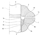
特に本発明においては、図2に示すように、シール面部8が、ラジアル軸受部6寄りに形成されたラジアル軸受部寄り傾斜面としての第1傾斜面8aと、この第1傾斜面8aよりもラジアル軸受部6から離れた側に形成された離間傾斜面としての第2傾斜面8bとで構成されている。そして、このシール面部8における第1傾斜面8aのシャフト軸Xに対するラジアル軸受部6側からの傾斜角度αを、第2傾斜面8bのシャフト軸Xに対するラジアル軸受部6側からの傾斜角度β(なお、図2においては、第2傾斜面8bとシャフト軸Xとの交差部分が図外となるので、同等の傾斜角となる、シャフト軸Xに平行な軸線に対する傾斜角度βを示している)よりも大きく形成している。例えば、第1傾斜面8aの傾斜角度αは45度よりも大きい角度とされ、第2傾斜面8bの傾斜角度βは45度よりも小さい角度とされている。また、このシール面部8における第1傾斜面8aおよび第2傾斜面8bはそれぞれスリーブ1における開口端7に臨む内周部の箇所において全周にわたって凹凸部を有することなく円錐台形形状に形成されている。なお、図2における5aは潤滑油5の液面で、潤滑油5は、第1傾斜面8aを越えて第2傾斜面8bに接するような量が充填されている。
In particular, in the present invention, as shown in FIG. 2, the
この構成によれば、シール面部8を複数の傾斜面8a,8bにより構成させるとともに、シール面部8におけるラジアル軸受部6寄りに形成された第1傾斜面8aの傾斜角度αを大きく形成したので、例えば、シール面部8全体を第2傾斜面8bの傾斜角度βと同じ傾斜角度の単一の傾斜面で構成した場合に比べて、シール面部8において十分な量の潤滑油5を保持できて、潤滑油5の一部が蒸発するなどしてその量が減少した場合でも、シール面部8に溜められた潤滑油5が毛細管現象によりラジアル軸受部6側に流入し、ラジアル軸受部6では常に潤滑油5が満たされた状態に保持されて、軸受性能が良好に維持される。また、シール面部8において開口端7側ほど広がる形状であるので、高温時に潤滑油5が熱膨張した時の液面5aが開口端7側へ移動する(熱膨張した潤滑油5の体積分が開口端7側へ移動する)量を低減できる効果もある。しかも、シール面部8の開口端7からの深さLを、シール面部8全体を第2傾斜面8bの傾斜角度βと同じ傾斜角度の単一の傾斜面で構成した場合に比べて、小さくできるので、これにより、ラジアル軸受部6の寸法長さを十分にとることができて高い回転精度や十分な剛性を得ることができる。さらに、第1傾斜面8aよりも開口端7寄りに形成された第2の傾斜面8bの傾斜角度βは小さ目に形成されているので、回転駆動時でも潤滑油5に作用する遠心力が小さく抑えられて潤滑油5が外部に飛散することを防止でき、良好な信頼性を維持できる。
According to this configuration, the
なお、第1傾斜面8aを形成する範囲は、必要とする潤滑油5の量に応じて適宜決定されるが、シール面部8が設けられている箇所で十分な油量を確保できるように、その第2傾斜面8b側接続部のシャフト4外周面からの離間径方向寸法Dがラジアル軸受部6の箇所のスリーブ1内周面とシャフト4外周面との間の離間径方向寸法dの2倍以上であることが好ましい。
In addition, although the range which forms the 1st inclined
また、上記構成に加えて、図3に示すように、シャフト4における外部に露出する箇所に形成された断面略V字状の溝部4aに、潤滑油5を弾く撥油剤13を塗布してもよく、これによれば、潤滑油5の一部がシャフト4の外周面を伝わって流れ出ようとした場合でも、潤滑油5が前記撥油剤13により弾かれて外部に流れ出ることが防止される。また、さらに、スリーブ1における開口端7が設けられている端面1aにも撥油剤13を塗布してもよく、これによれば、スリーブ1における第2傾斜面8bから端面1aを伝わって流れ出ようとした場合でも、潤滑油5が前記撥油剤13により弾かれて外部に流れ出ることが防止される。
In addition to the above configuration, as shown in FIG. 3, an
なお、上記実施の形態においては、シール面部8が、第1傾斜面8aと第2傾斜面8bとに2分割されている場合を述べたが、これに限るものではなく、シャフト軸Xの方向に対して3つ以上分割された傾斜面で構成してもよい。例えば、図4に示すように、第2傾斜面8bよりもさらにラジアル軸受部6から離れた側に、第2傾斜面8bのシャフト軸Xに対するラジアル軸受部6側からの傾斜角度βよりも大きい傾斜角度γの第3傾斜面8cを面取り形状に形成してもよい。なお、図4においては、見易くするため、第3傾斜面8cとシャフト軸Xと同等の傾斜角度γとなる、シャフト軸Xに平行な軸線に対する傾斜角度γを示している。この場合には、スリーブ1における第2傾斜面8bと、開口端7が設けられている端面1aとが、第3傾斜面8cを介して比較的なだらかに接続されるので、スリーブ1を製造する切削工程などで、接続部においてバリなどを生じることを最小限に抑えることができる利点がある。なお、図2〜図4に示すように、潤滑油5は、その液面5aが、第1傾斜面8aを越えて第2傾斜面8bに接するような量が充填されている。また、シール面部8をさらにシャフト軸Xに対して4つ以上分割してもよく、このような場合は、何れかの特定傾斜面のシャフト軸に対する傾斜角度が、この特定傾斜面よりもラジアル軸受部から離れた側に形成された少なくとも1つの離間傾斜面のシャフト軸に対する傾斜角度よりも大きく形成されていればよく、この構成により、上記と同様な作用効果を得ることができる。
In the above embodiment, the case where the
ところで、スリーブ1とシャフト4との間に潤滑油5を注入する場合には、一般には、スリーブ1とシャフト4との間を含めた空間を真空に近い状態まで減圧し、スリーブ1の開口端7が上方になるように配置した姿勢で開口端7側から潤滑油5を注入することが行われるが、上記したように、シール面部8において潤滑油5を多く保持できながら、シール面部8を全て傾斜面8a,8b,8c(または傾斜面8a,8b)により構成することにより、潤滑油5をスムーズに、シール面部8からラジアル軸受部6側に導入させることができる利点がある。
By the way, when the lubricating
また、図5に示すように、ラジアル軸受部6と第1傾斜面8aとの接続部8dや、第1傾斜面8aと第2傾斜面8bとの接続部8e、第2傾斜面8bとスリーブ端面1aとの接続部8fなどをなだらかな断面形状に形成してもよい。
Further, as shown in FIG. 5, the connecting
この構成によれば、スリーブ1を製造する切削工程などで、接続部8d,8e,8fにおいてバリなどを生じることをほぼ確実に防止することができる。また、潤滑油5を一層スムーズにシール面部8からラジアル軸受部6側に導入させることができる利点もある。
According to this configuration, it is possible to almost certainly prevent burrs and the like from being generated in the
さらに、図6に示すように、スリーブ1の端面1aに、シール面部8の開口端7部分を覆うカバー14を取り付けてもよく、この構成によれば、潤滑油5が外部に飛散することを一層確実に防止でき、これによれば、さらに信頼性が向上する。さらに、この場合に、シール面部8に臨むカバー14の下面にも撥油剤13を塗布してもよく、これによれば、潤滑油5がカバー14の下面に付着することも防止でき、一層信頼性が向上する。
Furthermore, as shown in FIG. 6, a
また、何れの実施の形態においても、シール面部8が、第1傾斜面8aおよび第2傾斜面8b、または第1傾斜面8a、第2傾斜面8bおよび第3傾斜面8cにより、それぞれスリーブ1における開口端7に臨む内周部の箇所において全周にわたって、つまり一部のみの小さな凹凸部分などを有することなく、円錐台形形状に形成されているので、これによっても、潤滑油5を、シール面部8からラジアル軸受部6側に導入させる際に、凹凸部などにより流れが阻害されることなく、一層スムーズに流れ込ませることができる利点がある。
In any of the embodiments, the
また、上記実施の形態においては、何れも、スリーブ1の一方が開口されているとともに他方が閉じられて、シャフト4の一端側だけが突出された構成である場合を述べ、この場合には、シール面部8がスリーブ1の片側だけに設けられる。しかしながら、これに限るものではなく、例えば、図7に示すように(この図7においては単なる流体軸受部分を有する場合を示している)、スリーブ1の両側からシャフト4の両端部が突出する構成のものにも適用可能であり、この場合には、同様の複数の傾斜面8a,8b等を有するシール面部8をスリーブ1の両端の開口端7に臨む内周面にそれぞれ形成すればよい。
Further, in the above-described embodiments, the case where one of the
本発明は、ハードディスク装置用スピンドルモータなどに加えて、ビデオテープレコーダやその他のモータの流体軸受装置に適しているが、その他の回転部を支持する軸受として用いることができる。 The present invention is suitable for a hydrodynamic bearing device of a video tape recorder and other motors in addition to a spindle motor for a hard disk device, but can be used as a bearing for supporting other rotating parts.
1 スリーブ
2 ハブ
3 スピンドルモータ部
4 シャフト
5 潤滑油
5a 液面
6 ラジアル軸受部
7 開口端
8 シール面部
8a 第1傾斜面(ラジアル軸受部寄り傾斜面)
8b 第2傾斜面(離間傾斜面)
8c 第3傾斜面
9 スラストフランジ
10 スラストプレート
12 スラスト軸受部
13 撥油剤
14 カバー
DESCRIPTION OF
8b Second inclined surface (separated inclined surface)
8c 3rd inclined surface 9
Claims (3)
このスリーブに所定隙間を介して挿入されたシャフトと、
このスリーブにシャフトを回転自在に支持させるラジアル軸受部と、
ラジアル軸受部の箇所を含めてスリーブとシャフトとの間の隙間に充填された潤滑油と、
スリーブにおける開口端に臨む箇所において、ラジアル軸受部の部分よりも大きい隙間を有するように形成されて、シャフトとの隙間部分に潤滑油が充填されるシール面部と
を備えた流体軸受装置であって、
前記シール面部の断面形状が、複数の傾斜面で構成され、
前記シール面部における、ラジアル軸受部寄りに形成されたラジアル軸受部寄り傾斜面のシャフト軸に対する傾斜角度が、このラジアル軸受部寄り傾斜面よりもラジアル軸受部から離れた側に形成された少なくとも1つの離間傾斜面のシャフト軸に対する傾斜角度よりも大きく形成された流体軸受装置。 Sleeve,
A shaft inserted into the sleeve through a predetermined gap;
A radial bearing that rotatably supports the shaft on the sleeve;
Lubricating oil filled in a gap between the sleeve and the shaft including the radial bearing portion;
A hydrodynamic bearing device including a seal face portion that is formed so as to have a gap larger than a radial bearing portion at a location facing the opening end of the sleeve and is filled with lubricating oil in the gap portion with the shaft. ,
The cross-sectional shape of the seal surface portion is composed of a plurality of inclined surfaces,
In the seal surface portion, an inclination angle of the inclined surface near the radial bearing portion formed near the radial bearing portion with respect to the shaft axis is at least one formed on the side farther from the radial bearing portion than the inclined surface close to the radial bearing portion. A hydrodynamic bearing device formed larger than an inclination angle of a separated inclined surface with respect to a shaft axis.
Priority Applications (3)
| Application Number | Priority Date | Filing Date | Title |
|---|---|---|---|
| JP2003391535A JP2005155689A (en) | 2003-11-21 | 2003-11-21 | Hydrodynamic bearing device |
| US10/972,495 US7201516B2 (en) | 2003-11-21 | 2004-10-26 | Fluid bearing device |
| CNB2004100974429A CN100485208C (en) | 2003-11-21 | 2004-11-19 | Fluid bearing device |
Applications Claiming Priority (1)
| Application Number | Priority Date | Filing Date | Title |
|---|---|---|---|
| JP2003391535A JP2005155689A (en) | 2003-11-21 | 2003-11-21 | Hydrodynamic bearing device |
Publications (1)
| Publication Number | Publication Date |
|---|---|
| JP2005155689A true JP2005155689A (en) | 2005-06-16 |
Family
ID=34587486
Family Applications (1)
| Application Number | Title | Priority Date | Filing Date |
|---|---|---|---|
| JP2003391535A Withdrawn JP2005155689A (en) | 2003-11-21 | 2003-11-21 | Hydrodynamic bearing device |
Country Status (3)
| Country | Link |
|---|---|
| US (1) | US7201516B2 (en) |
| JP (1) | JP2005155689A (en) |
| CN (1) | CN100485208C (en) |
Cited By (5)
| Publication number | Priority date | Publication date | Assignee | Title |
|---|---|---|---|---|
| US8277125B2 (en) | 2009-06-12 | 2012-10-02 | Nidec Corporation | Bearing apparatus, spindle motor, and disk drive apparatus |
| US8337086B2 (en) | 2009-06-18 | 2012-12-25 | Nidec Corporation | Bearing apparatus, spindle motor, and disk drive apparatus |
| US8472132B2 (en) | 2008-05-26 | 2013-06-25 | Nidec Corporation | Fluid dynamic bearing apparatus arranged to discharge air bubbles generated therein and a spindle motor and a disk drive apparatus including the same |
| US8690435B2 (en) | 2009-11-25 | 2014-04-08 | Nidec Corporation | Dynamic pressure bearing and spindle motor using the same |
| JP2020193637A (en) * | 2019-05-24 | 2020-12-03 | イーグル工業株式会社 | Solenoid valve |
Families Citing this family (43)
| Publication number | Priority date | Publication date | Assignee | Title |
|---|---|---|---|---|
| JP4566565B2 (en) * | 2004-01-14 | 2010-10-20 | Ntn株式会社 | Hydrodynamic bearing device |
| US7675210B2 (en) * | 2005-03-11 | 2010-03-09 | Panasonic Corporation | Hydrodynamic bearing and method for manufacturing the same, and spindle motor and method for manufacturing the same |
| CN1940322A (en) * | 2005-09-30 | 2007-04-04 | 富准精密工业(深圳)有限公司 | Fluid dynamical-pressure bearing |
| JP2007113705A (en) * | 2005-10-20 | 2007-05-10 | Minebea Co Ltd | Fluid dynamic bearing device, motor, and disk storage device |
| JP2007170641A (en) * | 2005-12-26 | 2007-07-05 | Matsushita Electric Ind Co Ltd | Hydrodynamic bearing device and manufacturing method thereof, spindle motor and recording / reproducing device |
| JP2008157444A (en) * | 2006-12-01 | 2008-07-10 | Matsushita Electric Ind Co Ltd | Hydrodynamic bearing device, spindle motor equipped with the same, and information recording / reproducing device |
| CN101210586B (en) | 2006-12-29 | 2010-11-10 | 富准精密工业(深圳)有限公司 | Dynamical pressure bearing manufacturing method |
| DE102007001963B4 (en) * | 2007-01-13 | 2021-04-22 | Schaeffler Technologies AG & Co. KG | Rolling bearing with a device for draining off a liquid |
| JP2008187848A (en) * | 2007-01-31 | 2008-08-14 | Denso Corp | Stepping motor |
| JP2008190620A (en) * | 2007-02-05 | 2008-08-21 | Ntn Corp | Fluid bearing device |
| CN101280805B (en) * | 2007-04-06 | 2010-04-14 | 富准精密工业(深圳)有限公司 | Rolling body |
| JP2008281104A (en) * | 2007-05-10 | 2008-11-20 | Nippon Densan Corp | Sleeve, motor, recording disk driving device and method of manufacturing sleeve |
| JP2009201309A (en) * | 2008-02-25 | 2009-09-03 | Nippon Densan Corp | Spindle motor and storage disk drive apparatus |
| DE102008021514A1 (en) * | 2008-04-30 | 2009-11-12 | Minebea Co., Ltd. | Fluid dynamic bearing |
| JP2010014151A (en) * | 2008-07-01 | 2010-01-21 | Oki Data Corp | Bearing member, belt unit and image forming device |
| JP4977150B2 (en) * | 2009-02-04 | 2012-07-18 | アルファナテクノロジー株式会社 | Method for manufacturing fluid dynamic bearing |
| US8794839B2 (en) | 2009-06-12 | 2014-08-05 | Nidec Corporation | Bearing apparatus, spindle motor, and disk drive apparatus |
| US8370868B2 (en) * | 2010-08-18 | 2013-02-05 | Samsung Electro-Mechanics Co., Ltd. | Spindle motor and disk driver having the same |
| KR101133365B1 (en) | 2010-11-18 | 2012-04-06 | 엘지이노텍 주식회사 | Spindle motor |
| CN102122854A (en) * | 2011-04-18 | 2011-07-13 | 重庆德马变频电机研发制造有限公司 | Rotor for high-speed motor |
| JP2012225386A (en) * | 2011-04-18 | 2012-11-15 | Ntn Corp | Fluid dynamic pressure bearing device |
| KR20120136008A (en) * | 2011-06-08 | 2012-12-18 | 삼성전기주식회사 | Hydrodynamic bearing assembly and manufacturing method thereof |
| JP5892375B2 (en) | 2011-06-30 | 2016-03-23 | 日本電産株式会社 | Hydrodynamic bearing device and fan |
| KR101418905B1 (en) | 2011-09-30 | 2014-07-14 | 니혼 덴산 가부시키가이샤 | Motor and disk drive apparatus |
| KR20130035681A (en) * | 2011-09-30 | 2013-04-09 | 삼성전기주식회사 | Spindle motor |
| KR101418902B1 (en) | 2011-09-30 | 2014-07-14 | 니혼 덴산 가부시키가이샤 | Motor and disk drive apparatus |
| JP2013085447A (en) | 2011-09-30 | 2013-05-09 | Nippon Densan Corp | Motor and disk drive |
| CN103248162B (en) | 2012-02-01 | 2015-07-15 | 日本电产株式会社 | Motor and disk drive apparatus |
| JP5812351B2 (en) | 2012-05-30 | 2015-11-11 | 日本電産株式会社 | Bearing mechanism, motor and disk drive |
| JP2014005933A (en) | 2012-05-30 | 2014-01-16 | Nippon Densan Corp | Bearing mechanism, motor and disk driving device |
| JP2014005934A (en) | 2012-05-30 | 2014-01-16 | Nippon Densan Corp | Bearing mechanism, motor and disk driving device |
| JP2014023205A (en) | 2012-07-13 | 2014-02-03 | Nippon Densan Corp | Motor, and disc driving device |
| JP2014059008A (en) | 2012-09-18 | 2014-04-03 | Nippon Densan Corp | Bearing device, spindle motor, and disc driving device |
| JP2014059009A (en) | 2012-09-18 | 2014-04-03 | Nippon Densan Corp | Bearing device, spindle motor, and disc driving device |
| JP2014105783A (en) * | 2012-11-28 | 2014-06-09 | Samsung Electromechanics Japan Advanced Technology Co Ltd | Rotary equipment |
| US8773816B1 (en) | 2013-03-13 | 2014-07-08 | Nidec Corporation | Spindle motor with hydrodynamic bearing structure having capillary seal and disk drive apparatus including same |
| US8797678B1 (en) | 2013-03-14 | 2014-08-05 | Nidec Corporation | Spindle motor and disk drive apparatus |
| US8941946B2 (en) | 2013-03-14 | 2015-01-27 | Nidec Corporation | Motor including dynamic bearing with seal portion and disk drive apparatus including the same |
| EP2803875B1 (en) * | 2013-05-13 | 2019-03-13 | Aktiebolaget SKF | Landing bearing and magnetic bearing assembly |
| EP2803874B1 (en) * | 2013-05-13 | 2019-08-14 | Aktiebolaget SKF | Landing bearing and magnetic bearing assembly |
| US9341214B2 (en) * | 2013-07-24 | 2016-05-17 | Nidec Corporation | Sleeve, fluid dynamic pressure bearing including the sleeve, spindle motor including the fluid dynamic pressure bearing and electronic equipment including the spindle motor |
| US9001460B2 (en) | 2013-08-21 | 2015-04-07 | Nidec Corporation | Spindle motor, and disk drive apparatus |
| CN108338647A (en) * | 2018-04-20 | 2018-07-31 | 常州汇丰粉末冶金有限公司 | Fruit juice mixer propeller shaft tube and its manufacturing method |
Family Cites Families (9)
| Publication number | Priority date | Publication date | Assignee | Title |
|---|---|---|---|---|
| US5427456A (en) * | 1994-04-12 | 1995-06-27 | Synektron Corporation | Fluid bearing with asymmetrical groove pattern |
| US5423612A (en) * | 1994-09-16 | 1995-06-13 | Quantum Corp. | Hydrodynamic bearing and seal |
| JP2937833B2 (en) | 1994-11-15 | 1999-08-23 | 株式会社三協精機製作所 | Bearing sealing device |
| US5667309A (en) * | 1994-11-15 | 1997-09-16 | Sankyo Seiki Mfg. Co., Ltd. | Bearing seal system |
| JP3933692B2 (en) * | 1995-12-22 | 2007-06-20 | コーニンクレッカ フィリップス エレクトロニクス エヌ ヴィ | Dynamic groove bearing with V-shaped oil barrier groove |
| US6296391B1 (en) * | 1997-06-09 | 2001-10-02 | Sankyo Seiki Mfg. Co., Ltd. | Hydrodynamic bearing apparatus |
| US6890104B2 (en) * | 2000-07-10 | 2005-05-10 | Kabushi Kaisha Sankyo Seiki Seisakusho | Hydrodynamic bearing device |
| JP4248176B2 (en) * | 2001-12-14 | 2009-04-02 | 株式会社ジェイテクト | Hydrodynamic bearing |
| JP2003247547A (en) * | 2002-02-26 | 2003-09-05 | Tokyo Parts Ind Co Ltd | Fluid bearing mechanism and brushless motor equipped with fluid bearing mechanism |
-
2003
- 2003-11-21 JP JP2003391535A patent/JP2005155689A/en not_active Withdrawn
-
2004
- 2004-10-26 US US10/972,495 patent/US7201516B2/en not_active Expired - Lifetime
- 2004-11-19 CN CNB2004100974429A patent/CN100485208C/en not_active Expired - Lifetime
Cited By (6)
| Publication number | Priority date | Publication date | Assignee | Title |
|---|---|---|---|---|
| US8472132B2 (en) | 2008-05-26 | 2013-06-25 | Nidec Corporation | Fluid dynamic bearing apparatus arranged to discharge air bubbles generated therein and a spindle motor and a disk drive apparatus including the same |
| US8277125B2 (en) | 2009-06-12 | 2012-10-02 | Nidec Corporation | Bearing apparatus, spindle motor, and disk drive apparatus |
| US8337086B2 (en) | 2009-06-18 | 2012-12-25 | Nidec Corporation | Bearing apparatus, spindle motor, and disk drive apparatus |
| US8690435B2 (en) | 2009-11-25 | 2014-04-08 | Nidec Corporation | Dynamic pressure bearing and spindle motor using the same |
| JP2020193637A (en) * | 2019-05-24 | 2020-12-03 | イーグル工業株式会社 | Solenoid valve |
| JP7171509B2 (en) | 2019-05-24 | 2022-11-15 | イーグル工業株式会社 | solenoid valve |
Also Published As
| Publication number | Publication date |
|---|---|
| US7201516B2 (en) | 2007-04-10 |
| CN100485208C (en) | 2009-05-06 |
| CN1619175A (en) | 2005-05-25 |
| US20050111769A1 (en) | 2005-05-26 |
Similar Documents
| Publication | Publication Date | Title |
|---|---|---|
| JP2005155689A (en) | Hydrodynamic bearing device | |
| JP4930611B2 (en) | Fluid dynamic pressure bearing and spindle motor | |
| US5558443A (en) | Shaft seal for hydrodynamic bearing unit | |
| JP4700394B2 (en) | Fluid dynamic pressure bearing, spindle motor equipped with the fluid dynamic pressure bearing, and recording disk drive | |
| JP5212690B2 (en) | Fluid dynamic bearing mechanism, motor and recording disk drive | |
| US6900568B2 (en) | Fluid dynamic bearing motor configured with an integrated counterplate to contain bearing fluid | |
| JP2005114165A (en) | Fluid dynamic pressure bearing, spindle motor, and hard disk drive device | |
| JP2005155912A (en) | Fluid dynamic bearing and spindle motor | |
| JP2005155912A5 (en) | ||
| JP2010078100A (en) | Fluid bearing device, spindle motor with the device, and information device | |
| JP4473716B2 (en) | Fluid dynamic bearing device, spindle motor provided with the fluid dynamic bearing device, and recording disk drive device | |
| JP4788163B2 (en) | Fluid dynamic pressure bearing and spindle motor | |
| JP2008190660A (en) | Bearing mechanism, motor, and recording disk drive device | |
| JP2005155690A (en) | Hydrodynamic bearing device | |
| JP2007292107A (en) | Fluid bearing type rotating device | |
| US7347625B2 (en) | Grooving in FDB motor capillary seal | |
| JP4278527B2 (en) | Spindle motor | |
| JP4511403B2 (en) | Spindle motor | |
| JP2002310146A (en) | Spindle motor | |
| JP3796641B2 (en) | Rolling bearing | |
| JP3450451B2 (en) | Spindle motor | |
| JP4752273B2 (en) | Spindle motor | |
| JP3959818B2 (en) | Hydrodynamic bearing device | |
| JP2005163918A (en) | Hydrodynamic bearing device | |
| JP2005009600A (en) | Hydrodynamic bearing device |
Legal Events
| Date | Code | Title | Description |
|---|---|---|---|
| A761 | Written withdrawal of application |
Free format text: JAPANESE INTERMEDIATE CODE: A761 Effective date: 20061102 |