JP2005159727A - Antenna device - Google Patents
Antenna device Download PDFInfo
- Publication number
- JP2005159727A JP2005159727A JP2003395430A JP2003395430A JP2005159727A JP 2005159727 A JP2005159727 A JP 2005159727A JP 2003395430 A JP2003395430 A JP 2003395430A JP 2003395430 A JP2003395430 A JP 2003395430A JP 2005159727 A JP2005159727 A JP 2005159727A
- Authority
- JP
- Japan
- Prior art keywords
- antenna
- earphone
- metal wires
- circuit board
- antenna device
- Prior art date
- Legal status (The legal status is an assumption and is not a legal conclusion. Google has not performed a legal analysis and makes no representation as to the accuracy of the status listed.)
- Abandoned
Links
Images

Landscapes
- Radio Transmission System (AREA)
- Details Of Aerials (AREA)
- Support Of Aerials (AREA)
Abstract
【課題】携帯用無線機端末のアンテナは、端末を小形化すると、効率の劣化や使用周波数の狭帯域化を起し、手での保持は人体により特性に悪影響を与える。高誘電率材料による別のチップアンテナは、効率が低く、使用周波数帯域も限られ、特性が人体の影響を受ける。
【解決手段】携帯用無線機本体の内部に設置された回路基板と第一、第二のイヤホンとの間に音声伝送路を形成するよう、それぞれ回路基板と回路基板からの線路が二つに分岐し、分岐先で第一、第二のイヤホンに接続される第一、第二の金属線を備え、第一、第二の金属線は第一イヤホンから第二のイヤホンまでの長さが略同一で、第一、第二の金属線は互いに非接触で近接して配置され、かつ分岐点近傍で異なるイヤホン側にそれぞれ第一、第二のインダクタを備え、分岐点より、イヤホン側の第一、第二の金属線でダイポールアンテナを形成する。
【選択図】図1An antenna of a portable radio terminal causes a deterioration in efficiency and a narrow band of a use frequency when the terminal is miniaturized, and holding by hand adversely affects characteristics by a human body. Another chip antenna made of a high dielectric constant material has low efficiency, has a limited frequency band, and is affected by the human body.
SOLUTION: There are two lines from the circuit board and the circuit board so that an audio transmission path is formed between the circuit board installed inside the portable radio main body and the first and second earphones. The first and second metal wires are branched and connected to the first and second earphones at the branch destination, and the first and second metal wires have a length from the first earphone to the second earphone. The first and second metal wires that are substantially the same, are arranged close to each other in a non-contact manner, and are provided with first and second inductors on different earphone sides near the branch point, respectively, from the branch point to the earphone side. A dipole antenna is formed with the first and second metal wires.
[Selection] Figure 1
Description
本発明は携帯電話機端末や携帯テレビ端末等の無線機端末に対して適用されるアンテナ装置に関するものである。 The present invention relates to an antenna device applied to a radio terminal such as a mobile phone terminal or a mobile TV terminal.
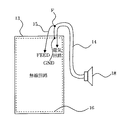
イヤホンコードをアンテナとして兼用する技術に、例えば特開平9-51222号公報に掲載されたものがある。図6はその概略構成図である。13は無線機、14は信号線、15は給電線、16はシールドケース、18はイヤホンまたはマイクである。イヤホンまたはマイク18が、信号線14を介して、無線機13の電気回路(音声処理回路)に接続され、この信号線14のうち接地側の線の一部が給電点Fとなり、給電線15と接続することで信号線14がアンテナ素子として動作するものである。
For example, Japanese Patent Application Laid-Open No. 9-51222 discloses a technique for using an earphone cord as an antenna. FIG. 6 is a schematic configuration diagram thereof. 13 is a wireless device, 14 is a signal line, 15 is a power supply line, 16 is a shield case, and 18 is an earphone or a microphone. The earphone or
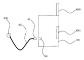
また、イヤホン部にアンテナ素子を搭載したアンテナダイバーシティ受信装置に関し、特開2001-251232号公報に記載されたものがある。図7はその概略構成図である。AN0は主アンテナ、AN1は副アンテナ、30はプラグ、60はイヤホンジャック、100は携帯電話機本体、200はイヤホン部、300はコードである。イヤホン200内には高誘電率材料で形成されるチップアンテナが搭載される。コード300が携帯電話機100に接続された状態で、このチップアンテナと主アンテナAN0とにより、ダイバーシティ受信が行われるものである。
Further, there is an antenna diversity receiving device in which an antenna element is mounted on an earphone unit, which is described in Japanese Patent Laid-Open No. 2001-251232. FIG. 7 is a schematic configuration diagram thereof. AN0 is a main antenna, AN1 is a sub-antenna, 30 is a plug, 60 is an earphone jack, 100 is a mobile phone body, 200 is an earphone unit, and 300 is a cord. A chip antenna formed of a high dielectric constant material is mounted in the
近年、小形化の進む携帯電話機端末や携帯テレビ端末に代表される無線機端末は、ホイップアンテナ等のアンテナ素子を搭載している。これらの無線機端末は、アンテナ素子を含めた無線機端末全体の大きさを、所定の伝搬波長に対して十分に大きく確保できていない。このため、アンテナ素子だけでなく、無線機端末の内部の回路基板のグラウンドにも電波の送受信に寄与する電流が流れるので、回路基板の大きさ、さらには無線機端末の大きさも、アンテナの特性に大きな影響を与える。 2. Description of the Related Art In recent years, radio terminal devices such as mobile phone terminals and mobile TV terminals, which are becoming smaller, are equipped with antenna elements such as whip antennas. In these radio terminals, the size of the entire radio terminal including the antenna element cannot be secured sufficiently large for a predetermined propagation wavelength. For this reason, the current that contributes to the transmission and reception of radio waves flows not only to the antenna element but also to the ground of the circuit board inside the radio terminal, so the size of the circuit board and the size of the radio terminal also depend on the antenna characteristics It has a big influence on.
また無線機端末は、手で保持し使用する状況が多い。小形化された無線機端末は手で覆われる部分が多く、人体の影響からアンテナ効率は劣化する。 Radio terminals are often held and used by hand. Miniaturized radio terminals are often covered with hands, and antenna efficiency deteriorates due to the influence of the human body.
手の保持によるアンテナ効率の劣化を抑制するには、回路基板のグラウンドを流れる、電波の送受信に寄与する電流を少なくすればよい。そのために、アンテナ素子を長くすることも有効である。しかしながら、アンテナ素子を長くすると、アンテナの入力インピーダンスは高くなり、整合を図る際に使用できる周波数帯域も狭くなる。さらに、アンテナ素子の長さが、所定の伝搬波長の1/2、3/4、1程度となると、アンテナ素子上の電流分布には節が生じ、放射パターンにヌルが多く生じる。これは感度のよい通信を妨げるものとなる。さらに、アンテナ素子を長くすることは、無線機端末全体の小形化、デザイン性の向上に大きなデメリットを及ぼす。 In order to suppress deterioration of antenna efficiency due to holding of the hand, it is only necessary to reduce the current flowing through the ground of the circuit board and contributing to transmission / reception of radio waves. Therefore, it is also effective to lengthen the antenna element. However, when the antenna element is lengthened, the input impedance of the antenna is increased, and the frequency band that can be used for matching is also narrowed. Further, when the length of the antenna element is about 1/2, 3/4, or 1 of the predetermined propagation wavelength, nodes are generated in the current distribution on the antenna element, and a lot of nulls are generated in the radiation pattern. This hinders sensitive communication. Furthermore, lengthening the antenna element has a major demerit in reducing the size of the entire radio terminal and improving the design.
このようなことから、図6に示す従来のアンテナ装置では、無線機端末の大きさがアンテナ特性へ与える影響が大きく、無線機端末を小形化すると、アンテナ効率の劣化や、使用できる周波数の狭帯域化が引き起こされ、無線機端末の小形化や形状の自由性を阻害している。さらに、アンテナ特性は無線機端末を手で保持した際に人体による悪影響を受けやすい。
また、図7に示す従来のアンテナ装置では、チップアンテナを用いている。チップアンテナは高誘電率材料を用いており、一般的に誘電体損等によりアンテナ効率は低く、使用できる周波数帯域も極限られている。さらに、イヤホン部にチップアンテナを内蔵する関係上、アンテナ特性は人体の影響を強く受ける。
For this reason, in the conventional antenna apparatus shown in FIG. 6, the size of the radio terminal has a great influence on the antenna characteristics. If the radio terminal is miniaturized, the antenna efficiency is degraded and the usable frequency is narrowed. Bandwidth has been created, which has hindered the miniaturization and freedom of shape of radio terminals. Furthermore, the antenna characteristics are likely to be adversely affected by the human body when the radio terminal is held by hand.
In the conventional antenna device shown in FIG. 7, a chip antenna is used. The chip antenna uses a high dielectric constant material, and generally has low antenna efficiency due to dielectric loss or the like, and the usable frequency band is also limited. Furthermore, the antenna characteristics are strongly influenced by the human body because the chip antenna is built in the earphone unit.
本発明は、イヤホンコードの一部をそのままダイポールアンテナとして兼用するものである。このようにアンテナを形成すると、無線機端末の影響を受けない為、無線機端末を手で保持しても、アンテナ効率は劣化せず、安定した電波の送受信が可能となる。さらには、無線機本体の大きさや形状の自由度を高めることにもつながる。また、イヤホンコードの長さを適切に設定することで、半波長ダイポールアンテナを形成することが容易であり、使用可能な周波数帯域も確保できる。無線機端末に搭載されたアンテナとのダイバーシティ受信を行う際にも、用いるアンテナ間の距離を十分に離すことができ、且つアイソレーション特性も非常に良い為、高性能なダイバーシティ効果を実現できる。 In the present invention, a part of the earphone cord is also used as it is as a dipole antenna. When the antenna is formed in this way, it is not affected by the radio terminal, so that even if the radio terminal is held by hand, the antenna efficiency does not deteriorate and stable transmission / reception of radio waves is possible. Furthermore, it leads to increasing the degree of freedom of the size and shape of the radio main body. In addition, by appropriately setting the length of the earphone cord, it is easy to form a half-wave dipole antenna, and a usable frequency band can be secured. When performing diversity reception with the antenna mounted on the radio terminal, the distance between the antennas to be used can be sufficiently separated and the isolation characteristic is very good, so that a high-performance diversity effect can be realized.
本発明のアンテナ装置は、携帯用無線機本体の内部に設置された回路基板からの音声信号を二つに分岐してそれぞれ第一、第二のイヤホンに伝送する第一の金属線と、第二の金属線を備え、
前記第一の金属線の第一のイヤホンから第二のイヤホンまでの長さと、第二の金属線の第一イヤホンから第二のイヤホン迄の長さが略同一で、前記第一の金属線と第二の金属線は非接触で近接して配置され、さらに、第一の金属線の分岐点と第二の金属線の合流点近傍でかつイヤホン側にそれぞれ第一、第二のインダクタを備え、前記分岐点と合流点より、イヤホン側の前記第一、第二の金属線でダイポールアンテナを形成する。
The antenna device according to the present invention includes a first metal wire that branches an audio signal from a circuit board installed inside a portable radio main body into two parts and transmits them to the first and second earphones, respectively, With two metal wires,
The length of the first metal wire from the first earphone to the second earphone is substantially the same as the length of the second metal wire from the first earphone to the second earphone, and the first metal wire And the second metal wire are arranged close to each other in a non-contact manner, and the first and second inductors are arranged near the junction of the first metal wire and the junction of the second metal wire and on the earphone side, respectively. A dipole antenna is formed by the first and second metal wires on the earphone side from the branch point and the junction.
本発明のアンテナ装置は、イヤホンに音声信号を伝達する為のグラウンド線及び信号線をそのまま利用してダイポールアンテナを形成している為、ダイポールアンテナは、その特性が、回路基板2を内蔵する無線機本体1の大きさや、形状の影響を受けず、無線機本体1の大きさや形状の自由度を高めることができる。さらに、無線機本体1を手で保持してもアンテナ効率は劣化しない。本発明では、アンテナ専用の素子を別途イヤホンコードに内蔵した場合と比較し、イヤホンコードの軽量化、低コスト化に貢献している。また、イヤホンコードの長さを適切に設定することで、略1/2波長ダイポールアンテナを形成することも容易であり、使用できる周波数帯域を広く確保することもできる。また、無線機端末に搭載されたアンテナとのダイバーシティ受信を行う際にも、用いるアンテナ間の距離を十分に離すことができ、且つアイソレーション特性も非常に良い為、高性能なダイバーシティ効果を実現できる。 Since the antenna device of the present invention forms a dipole antenna by directly using a ground line and a signal line for transmitting an audio signal to the earphone, the characteristic of the dipole antenna is a wireless that incorporates the circuit board 2. The degree of freedom of the size and shape of the wireless device body 1 can be increased without being affected by the size and shape of the device body 1. Furthermore, the antenna efficiency does not deteriorate even if the radio main body 1 is held by hand. The present invention contributes to the reduction of the weight and cost of the earphone cord, as compared with the case where a dedicated antenna element is separately incorporated in the earphone cord. In addition, by setting the length of the earphone cord appropriately, it is easy to form a substantially ½ wavelength dipole antenna, and a wide usable frequency band can be secured. In addition, when performing diversity reception with the antenna mounted on the radio terminal, the distance between the antennas used can be sufficiently separated and the isolation characteristics are very good, realizing a high-performance diversity effect. it can.
実施の形態1.
以下、本発明の実施の形態について図を参照しながら説明する。なお、図中同一、または相当部分には同一符号を付してその説明は繰り返さない。
Embodiment 1 FIG.
Hereinafter, embodiments of the present invention will be described with reference to the drawings. In addition, the same code | symbol is attached | subjected to the same or an equivalent part in a figure, and the description is not repeated.
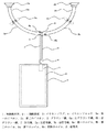
図1は本発明の実施の形態1を示す構成図である。本アンテナ装置はUHF帯テレビ放送視聴機能を備えた無線端末のアンテナ装置に関するもので、イヤホンコードの一部をダイポールアンテナとして兼用するものである。ここで使用するイヤホンコードはモノラルタイプである。
以下図に従い実施の形態1の構成を説明する。図において、1は無線機本体、2は無線機本体1の内部に設置された回路基板、3はイヤホンプラグ、4はイヤホンジャック、5aは第一のイヤホン、5bは第二のイヤホン、6はグラウンド線、6aはグラウンド線6の分岐後に第一のイヤホン5aと接続を行う左グラウンド線、6bはグラウンド線6の分岐後に第二のイヤホン5bと接続を行う右グラウンド線、7は信号線、7aは信号線7の分岐後に第一のイヤホン5aと接続を行う左信号線、7bは信号線7の分岐後に第二のイヤホン5bと接続を行う右信号線、8aは左グラウンド線6aの一部が分岐点近傍で螺旋状に巻かれた第一のコイル、8bは右信号線7bの一部が分岐点近傍で螺旋状に巻かれた第二のコイル、9aは左グラウンド線6a及び左信号線7aの一部が螺旋状に巻かれた第三のコイル、9bは右グラウンド線6b及び右信号線7bの一部が螺旋状に巻かれた第四のコイル、Sはアンテナとしての給電点で、それぞれ信号線7の分岐点、及びグラウンド線6の分岐点としている。
FIG. 1 is a block diagram showing Embodiment 1 of the present invention. This antenna device relates to an antenna device of a wireless terminal having a UHF band television broadcast viewing function, and a part of the earphone cord is also used as a dipole antenna. The earphone cord used here is a monaural type.
The configuration of the first embodiment will be described below with reference to the drawings. In the figure, 1 is a radio main unit, 2 is a circuit board installed inside the radio
グラウンド線6と、左グラウンド線6aと、右グラウンド線6bと、信号線7と、左信号線7aと、右信号線7bと、第一のコイル8aと、第二のコイル8bと、第三のコイル9aと、第四のコイル9bは全て図示されていない絶縁皮膜12に覆われている。なお、以下の本文に記載されるイヤホンコードとは、絶縁皮膜12に覆われた部分を示す。
なお、無線機本体1には図示されていない、スピーカー、ディスプレイ、電池、マイク、キーボード等が備わっている。回路基板2にはRF回路、ディジタル回路、画像処理回路、音声処理回路、バラン等が具備されている。
Ground line 6, left ground line 6a,
The wireless device main body 1 is provided with a speaker, a display, a battery, a microphone, a keyboard, and the like, which are not shown. The circuit board 2 includes an RF circuit, a digital circuit, an image processing circuit, an audio processing circuit, a balun, and the like.
次に実施の形態1の構成について更に詳細に説明する。無線機本体1に設置され、回路基板2に接続されたイヤホンプラグ3と、イヤホンジャック4が接続されることで、グラウンド線6及び信号線7は回路基板2と電気的に接続される。なお、グラウンド線6と信号線7は、回路基板2からイヤホン5a及びイヤホン5bへの音声信号伝送線路を形成する。グラウンド線6及び信号線7は、回路基板2から給電点Sまでの間を、高周波(ここではUHF帯の周波数)において平衡二線の伝送線路を形成する。グラウンド線6は給電点Sで左グラウンド線6a及び右グラウンド線6bに2分岐し、信号線7もまた給電点Sで左信号線7a及び右信号線7bに二分岐する。左グラウンド線6a及び左信号線7aは共に第一のイヤホン5aに接続され、右グラウンド線6b及び右信号線7bは共に第二のイヤホン5bに接続される。左グラウンド線6aは給電点Sの直近に第一のコイル8aを形成し、右信号線7bは給電点Sの直近に第二のコイル8bを形成する。
Next, the configuration of the first embodiment will be described in more detail. The ground line 6 and the
左グラウンド線6a及び左信号線7aは、給電点Sから第一のイヤホン5aの側に沿う、所定の伝搬波長の1/4程度(ここではUHF帯の周波数500MHzにおける波長の略1/4となる150mm)の位置に第三のコイル9aを形成し、右グラウンド線6b及び右信号線7bも同様に、給電点Sから第二のイヤホン5bの側に沿う、伝搬波長の1/4程度の位置に第四のコイル9bを形成する。左グラウンド線6a及び左信号線7aを近接して配置している為、左グラウンド線6a及び左信号線7aの間に、キャパシタが分布して接続された状態となり、UHF帯の周波数において、左グラウンド線6a及び左信号線7aを一つの金属線として扱っても差し支えない。右グラウンド線6b及び右信号線7bについても同様である。ここで、第一のコイル8a、第二のコイル8b、第三のコイル9a、第四のコイル9bは全て、UHF帯の周波数の電流を阻止する為に形成されたもので、コイルの巻き数やピッチを調整し、UHF帯の周波数におけるリアクタンスを十分に大きく(理想的には無限大)している。
The left ground line 6a and the left signal line 7a are about 1/4 of a predetermined propagation wavelength along the first earphone 5a side from the feeding point S (here, approximately 1/4 of the wavelength at a frequency of 500 MHz in the UHF band) The third coil 9a is formed at a position of 150 mm), and the
本発明による実施の形態1のアンテナは以上のように構成されている。第三のコイル9aにより、第三のコイル9aから第一のイヤホン5aまでの間の左グラウンド線6a及び左信号線7aに、UHF帯の周波数の電流は流れこまない。また、第四のコイル9bにより、第四のコイル9bから第二のイヤホン5bまでの間の右グラウンド線6b及び右信号線7bに、UHF帯の周波数の電流は流れこまない。このため、左グラウンド線6a及び左信号線7aにおける、給電点Sから第三のコイル9aまでの部分と、右グラウンド線6b及び右信号線7bの給電点Sから第四のコイルまでの部分が、UHF帯の周波数500MHzにおける略1/2波長ダイポールアンテナを形成する。
The antenna according to the first embodiment of the present invention is configured as described above. Due to the third coil 9a, a current having a frequency in the UHF band does not flow into the left ground line 6a and the left signal line 7a between the third coil 9a and the first earphone 5a. Further, the
なお、音声信号に用いられる周波数帯域は20Hz〜20kHzとUHF帯の周波数と比較し十分に小さいので第一のコイル8a、第二のコイル8b、第三のコイル9a、第四のコイル9bは全て、音声信号の伝達に支障をきたさない。ダイポールアンテナへの高周波電圧の印加は、UHF帯の周波数において平衡二線の伝送線路を形成するグラウンド線6及び信号線7により行われる。しかしながら、回路基板2は不平衡型回路である為、平衡二線の伝送線路を形成するグラウンド線6及び信号線7と、回路基板2との接続にはバラン(不平衡―平衡変換器)を介す必要があり、回路基板2にはバランが構成されている。なお、ダイポールアンテナは平衡型回路であり、伝送線路を形成するグラウンド線6及び信号線7と、ダイポールアンテナとの接続にはバランは必要ない。
Note that the frequency band used for the audio signal is sufficiently small compared to the frequency of 20Hz to 20kHz and the UHF band, so the first coil 8a, the
本発明の実施の形態1によるダイポールアンテナはこのように形成される。そのため、ダイポールアンテナの特性は、回路基板2を内蔵する無線機本体1の大きさや、形状の影響を受けず、無線機本体1の大きさや形状の自由度を高めることができる。さらに、無線機本体1を手で保持してもアンテナ効率は劣化しない。本発明では、イヤホン5に音声信号を伝達する為のグラウンド線6及び信号線7をそのまま利用してダイポールアンテナを形成している為、アンテナ専用の素子を別途イヤホンコードに内蔵した場合と比較し、イヤホンコードの軽量化、低コスト化に貢献している。また、イヤホンコードの長さを適切に設定することで、略1/2波長ダイポールアンテナを形成することも容易であり、使用できる周波数帯域を広く確保することもできる。
The dipole antenna according to Embodiment 1 of the present invention is formed in this way. Therefore, the characteristics of the dipole antenna are not affected by the size and shape of the radio main body 1 incorporating the circuit board 2, and the degree of freedom of the size and shape of the radio main body 1 can be increased. Furthermore, the antenna efficiency does not deteriorate even if the radio main body 1 is held by hand. In the present invention, since the dipole antenna is formed by using the ground line 6 and the
なお、実施の形態1ではダイポールアンテナを形成する為に、左グラウンド線6a、左信号線7a、右グラウンド線6b、右信号線7bのそれぞれの一部が螺旋状に巻かれた、第一のコイル8a、第二のコイル8b、第三のコイル9a、第四のコイル9bを形成したが、第一のコイル8a、第二のコイル8b、第三のコイル9a、第四のコイル9bの代わりにチップインダクタを接続しても構わない。
第三のコイル9aは、左グラウンド線6a及び左信号線7aの両方に形成したが、左信号線7aのみに形成しても構わない。第四のコイル9bは、右グラウンド線6b及び右信号線7bの両方に形成したが、右グラウンド線6bのみに形成しても構わない。
In the first embodiment, in order to form a dipole antenna, a part of each of the left ground line 6a, the left signal line 7a, the
The third coil 9a is formed on both the left ground line 6a and the left signal line 7a, but may be formed only on the left signal line 7a. The
第三のコイル9a及び第四のコイル9bを形成する代わりに、左グラウンド線6a及び左信号線7aにおいて、給電点Sから第一のイヤホン5aの側に沿う、所定の伝搬波長の1/4程度の位置にキャパシタを介して左グラウンド線6a及び左信号線7aを接続し、右グラウンド線6b及び右信号線7bにおいて、給電点Sから第二のイヤホン5bの側に沿う、所定の伝搬波長の1/4程度の位置にキャパシタを介して右グラウンド線6b及び右信号線7bを接続することで、所定の周波数における略1/2波長ダイポールを形成できる。
Instead of forming the third coil 9a and the
また、第三のコイル9a及び第四のコイル9bの代わりに、可変インダクタを接続することで、ダイポールアンテナの共振周波数を変化させることも可能である。これは、可変インダクタのリアクタンス値の変化に伴い、左グラウンド線6a及び左信号線7aの可変インダクタからイヤホン5aまでの部分、あるいは右グラウンド線6b及び右信号線7bの可変インダクタからイヤホン5bまでの部分のUHF帯の周波数における電流の流れ方が変わる為である。この場合、可変インダクタに印加する逆バイアス電圧源は無線機本体1の内部に設置して構わない。左グラウンド線6a及び左信号線7aは近接して配置している為、左グラウンド線6a及び左信号線7aの間には、キャパシタが分布して接続された状態であるが、左グラウンド線6a及び左信号線7aの間を、所定の波長に対して十分に小さい間隔で、実際にチップキャパシタを接続しても良い。右グラウンド線6b及び右信号線7bに関しても同様である。
Further, it is possible to change the resonance frequency of the dipole antenna by connecting a variable inductor instead of the third coil 9a and the
左グラウンド線6a及び左信号線7aにおける、第三のコイル9aから第一のイヤホン5aまでの部分と、右グラウンド線6b及び右信号線7bにおける、第四のコイル9bから第二のイヤホン5bまでの部分に高周波の電流が誘起されると、ダイポールアンテナの諸特性に影響を与える。この誘起された高周波の電流を抑制する為の手段として、左グラウンド線6a及び左信号線7aにおける第三のコイル9aから第一のイヤホン5aまでの部分と、右グラウンド線6b及び右信号線7bにおける第四のコイル9bから第二のイヤホン5bまでの部分に磁性体塗料を塗ったり、フェライトを巻きつけたりしても良い。
The part from the third coil 9a to the first earphone 5a in the left ground line 6a and the left signal line 7a, and the
ダイポールアンテナに対するインピーダンス整合は、回路基板2で行っても良いが、給電点S付近で行うことで使用可能な周波数帯域を広く保つことができる。これは回路基板2から給電点Sまでに延在するイヤホンコードの長さが周波数特性を持つ為、インピーダンス整合を図る上で使用できる周波数帯域を狭くしてしまうからである。インピーダンス整合の一環として整合回路に共振器を挿入すると、使用可能な周波数帯域をさらに広くすることができる。 Impedance matching for the dipole antenna may be performed on the circuit board 2, but by using it near the feeding point S, a usable frequency band can be kept wide. This is because the length of the earphone cord extending from the circuit board 2 to the feeding point S has frequency characteristics, and therefore the frequency band that can be used for impedance matching is narrowed. When a resonator is inserted into the matching circuit as part of impedance matching, the usable frequency band can be further widened.
実施の形態1に示したイヤホンコードは左右対称な構造となっているが、非対称な構造でもよく、ダイポールアンテナも非対称な構造となっても構わない。この場合、左グラウンド線6a及び左信号線7aにおける給電点Sから第三のコイル9aまでの長さと、右グラウンド線6b及び右信号線7bにおける給電点Sから第四のコイル9bまでの長さの総和が所定の伝搬波長の1/2程度となるように、第三のコイル及び第四のコイルを配置する位置を決めれば良い。
The earphone cord shown in the first embodiment has a symmetrical structure, but may have an asymmetric structure, and the dipole antenna may have an asymmetric structure. In this case, the length from the feeding point S to the third coil 9a in the left ground line 6a and the left signal line 7a, and the length from the feeding point S to the
実施の形態2.
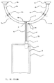
図2は本発明の実施の形態2を示すもので、UHF帯テレビ放送視聴機能を備えた、無線端末のアンテナ装置に関するものである。実施の形態1ではモノラルタイプのイヤホンコードを使用したが、実施の形態2ではステレオタイプのイヤホンコードを使用している。実施の形態1との違いは、信号線7を信号線7Lと信号線7Rの2本に分け設け、信号線7Rをグラウンド線6に近接して配置している点である。
Embodiment 2. FIG.
FIG. 2 shows Embodiment 2 of the present invention, which relates to an antenna device for a wireless terminal having a UHF band television broadcast viewing function. In Embodiment 1, a monaural earphone cord is used, but in Embodiment 2, a stereo type earphone cord is used. The difference from the first embodiment is that the
動作原理は実施の形態1と同じである。回路基板2から給電点Sまでの部分で形成する、UHF帯の周波数における平衡二線の伝送線路は、グラウンド線6及び信号線7Lによって構成される。信号線7Rとグラウンド線6は近接して配置する為、信号線7Rとグラウンド線6の間に、キャパシタが分布して接続された状態となり、UHF帯の周波数において信号線7Rとグラウンド線6を一つの金属線として扱っても差し支えない。左グラウンド線6a及び左信号線7aと、右グラウンド線6b及び右信号線7bにおいて、給電点Sからイヤホン5a及びイヤホン5bまでの間の構成は実施の形態1と全て同じである。
The operation principle is the same as in the first embodiment. A balanced two-wire transmission line at a frequency in the UHF band, which is formed in a portion from the circuit board 2 to the feeding point S, is configured by the ground line 6 and the
なお、UHF帯の周波数における平衡二線の伝送線路は、回路基板2から給電点Sまでの間で、信号線7Rと信号線7Lを近接して配置し、信号線7R及び信号線7Lの間に、キャパシタが分布して接続された状態とすることで、UHF帯の周波数において信号線7R及び信号線7Lを一つの金属線として扱うことで構成しても構わない。同様に、回路基板2から給電点Sまでの間で、信号線7Lとグラウンド線6を近接して配置し、信号線7L及びグラウンド線6の間に、キャパシタが分布して接続された状態とすることで、UHF帯の周波数において信号線7L及びグラウンド線6を一つの金属線として扱うことで構成しても構わない。さらに、UHF帯の周波数におけるこれらの平衡二線の伝送線路の構成の仕方は、近接して金属線同士を配置する代わりに、所定の伝播波長に対して十分に狭い間隔でこれらの金属線同士をチップキャパシタで接続することで構成しても構わない。
以上のように構成することで、ステレオタイプの音声信号に対応することができる。
Note that the balanced two-wire transmission line at the UHF band frequency is arranged between the
By configuring as described above, it is possible to deal with stereo type audio signals.
実施の形態3.
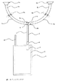
図3は本発明の実施の形態3を示すもので、UHF帯テレビ放送視聴機能を備えた、無線端末のアンテナ装置に関するもので、イヤホンコードにはモノラルタイプを使用している。実施の形態1との違いは、無線機本体1に収納可能なホイップアンテナ10が回路基板2に接続され、回路基板2には図示されていないダイバーシティ受信処理部が搭載され、本発明によるダイポールアンテナと、ホイップアンテナ10とでダイバーシティ受信が可能となることである。ダイバーシティ処理部では、ダイポールアンテナと、ホイップアンテナ10との電気的な接続を切り替えられるスイッチが備えられ、両アンテナどちらの復調データを採用するかが決定される。
FIG. 3 shows a third embodiment of the present invention, which relates to an antenna device of a wireless terminal having a UHF band TV broadcast viewing function, and uses a monaural earphone cord. The difference from the first embodiment is that a
一般的にダイバーシティ受信は、用いるアンテナ間の距離を、所定の伝搬波長の1/2程度離すことで、良好な効果が獲られると言われている。回路基板にアンテナ素子を複数接続し、これらのアンテナ素子を用いてダイバーシティ受信を行うと、アンテナ間の距離が確保できず、アイソレーション特性も悪い為、良好なダイバーシティ効果が得られない。 In general, diversity reception is said to have a good effect by separating the distance between antennas to be used by about a half of a predetermined propagation wavelength. When a plurality of antenna elements are connected to a circuit board and diversity reception is performed using these antenna elements, the distance between the antennas cannot be secured and the isolation characteristics are poor, so that a good diversity effect cannot be obtained.
本発明では、無線機本体1から給電点Sまでのイヤホンコードの長さを略300mm以上とすると、ダイポールアンテナとホイップアンテナ10との距離がUHF帯の周波数500MHzにおける波長の略1/2以上に確保できる。この長さは実際の使用における利便性の面からも、十分に実用的な長さである。また、実施の形態1で述べたように、ダイポールアンテナは、無線機本体1にアンテナ特性が影響されないという特徴もあり、ダイポールアンテナとホイップアンテナ10とのアイソレーション特性は良好である。本発明のこれらの特徴は、ダイバーシティ受信を行う上で非常に有利なものとなる。また、ホイップアンテナ10とダイポールアンテナの偏波面は同一に固定されるわけではないので、偏波ダイバーシティとしての高いクオリティも持ち合わせることを示唆している。
In the present invention, when the length of the earphone cord from the radio main unit 1 to the feeding point S is approximately 300 mm or more, the distance between the dipole antenna and the
なお、前記ダイバーシティ受信処理部は、ダイポールアンテナと、ホイップアンテナ10それぞれからの受信電力を最大比合成する、合成ダイバーシティを行うようにしたものであっても良い。回路基板2に接続されるダイポールアンテナ以外のアンテナ素子は、ホイップアンテナ10に限らない。また、回路基板2にはダイポールアンテナおよびホイップアンテナ10の他にも複数のアンテナ素子を接続しても構わない。
Note that the diversity reception processing unit may perform combining diversity by combining the received power from each of the dipole antenna and the
実施の形態4.
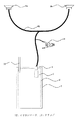
図4は本発明の実施の形態4を示すもので、UHF帯テレビ放送視聴機能を備えた無線端末のアンテナ装置に関するものである。実施の形態4において、7cは同軸ケーブルの内導体、7dは同軸ケーブルの内導体7cの分岐後に第一のイヤホン5aと接続を行う左信号線、7eは同軸ケーブルの内導体7cの分岐後に第二のイヤホン5bと接続を行う右信号線、6は同軸ケーブルの外導体、6dは同軸ケーブルの外導体6における給電点S側の端部と第一のイヤホン5aを接続する左グラウンド線、6eは同軸ケーブルの外導体6における給電点S側の端部と第二のイヤホン5bを接続する右グラウンド線、8cは左信号線7dの一部が螺旋状に巻かれた第五のコイル、8dは右グラウンド線6eの一部が螺旋状に巻かれた第六のコイル、9cは左信号線7d及び左グラウンド線6dの一部が螺旋状に巻かれた第七のコイル、9dは右信号線7e及び右グラウンド線6eの一部が螺旋状に巻かれた第八のコイル、11はチョーク構造を持つ導体であり、一部が外導体6cと導通する。
FIG. 4 shows
実施の形態3との違いは、回路基板2から給電点Sまでの間にグラウンド線6及び信号線7で構成されるUHF帯の周波数における平衡二線の伝送線路を、同軸ケーブルで形成している点、及び外導体6cの外側にUHF帯の周波数の電流が流れにくいようにチョーク構造11を持たせている点である。なお、給電点Sから第一のイヤホン5a及び第二のイヤホン5bを接続する左信号線7d及び右信号線7eと、左グラウンド線6d及び右グラウンド線6eによるダイポールアンテナの形成方法は実施の形態3と同様である。
The difference from the third embodiment is that a balanced two-wire transmission line in the UHF band frequency composed of the ground line 6 and the
回路基板2と前記同軸ケーブルは共に不平衡型回路である為、回路基板2と前記同軸ケーブルの接続にバランは介さなくて良い。しかし、ダイポールアンテナは平衡型回路である為、給電点Sでは高周波(ここではUHF帯の周波数) において反射電流が生じる。反射したUHF帯の周波数の電流は外導体6cの外側を流れる。この電流による放射を低減する為、外導体6cをチョーク構造11とする。図4に示すように、チョーク構造11は前記同軸ケーブルと概略平行な円筒状の導体で、給電点S側を開放、回路基板2側を外導体6cと短絡する。図4に示すチョーク構造11の長さLを所定の伝搬波長の略1/4にすることで、所定の周波数においては、給電点Sから回路基板2側を見込んだ外導体6cの外側の入力インピーダンスは無限大となり、給電点Sからの反射電流は流れなくなる。ここで外導体6cとチョーク構造11との間隔dをある程度広くとると、反射電流の流れにくくなる周波数帯域を広げることが可能である。チョーク構造11を形成する代わりに、外導体6cにフェライトを巻きつける、若しくは磁性体塗料を塗っても良い。実施の形態4では、UHF帯の周波数における伝送線路を同軸ケーブルで形成した為、信号線である内導体7cが外導体6cでシールドされ外乱による影響を受けにくくなる。
Since the circuit board 2 and the coaxial cable are both unbalanced circuits, a balun need not be interposed between the circuit board 2 and the coaxial cable. However, since the dipole antenna is a balanced circuit, a reflection current is generated at a high frequency (here, a frequency in the UHF band) at the feeding point S. The reflected UHF band frequency current flows outside the outer conductor 6c. In order to reduce the radiation due to this current, the outer conductor 6c is formed as a
実施の形態5.
図5は本発明の実施の形態5を示すもので、UHF帯テレビ放送視聴機能を備えた無線端末のアンテナ装置に関するものであり、アンテナの基本動作は実施の形態3と同じである。12はイヤホンコード、13はクリップで、イヤホンコード12とつながっており、イヤホンコード12が無線端末使用者の衣服と固定できるようにしたものである。
なお、イヤホンコード12は実施の形態1〜実施の形態4で説明したもののうちの何れか一つで構成されている。
Embodiment 5 FIG.
FIG. 5 shows a fifth embodiment of the present invention, which relates to an antenna device of a wireless terminal having a UHF band television broadcast viewing function, and the basic operation of the antenna is the same as that of the third embodiment. 12 is an earphone cord and 13 is a clip, which is connected to the earphone cord 12 so that the earphone cord 12 can be fixed to the clothes of the wireless terminal user.
The earphone cord 12 is composed of any one of those described in the first to fourth embodiments.
イヤホンコード12をクリップ13で無線端末使用者の衣服に固定すると、人体に対するダイポールアンテナの位置が変動しにくくなり、安定したアンテナ特性を得ることができる。また、ダイポールアンテナの位置が無線端末使用者の人体から離れるように衣服に固定することで、アンテナ効率を高めることもできる。さらに、イヤホンコード12を無線端末使用者の衣服に固定することは、耳にかかる力の負担を軽減することにもつながる。イヤホンコード12とクリップ13をつなげる部材は特定されないが、好ましくは金属でないほうが良い。クリップ13を構成する部材も同様である。クリップ13の設置箇所は図5に示すものに特定されるものではない。
When the earphone cord 12 is fixed to the clothes of the wireless terminal user with the
本発明は携帯電話機端末や携帯テレビ端末等の無線機端末に対しての適用に好適なものである。 The present invention is suitable for application to a radio terminal such as a mobile phone terminal or a mobile TV terminal.
1:無線機本体、2::回路基板、3:イヤホンプラグ、4:イヤホンジャック、5a:第一のイヤホン、5b:第二のイヤホン、6:グラウンド線、もしくは同軸ケーブルの外導体、6a、6d:左グラウンド線、6b、6e:右グラウンド線、7、7L、7R:信号線、7a、7d:左信号線、7b、7e:右信号線、7c:同軸ケーブルの内導体、8a:第一のコイル、8b:第二のコイル、9a:第三のコイル、9b:第四のコイル、10:ホイップアンテナ、11:チョーク構造導体、12:イヤホンコード、13:クリップ、S:給電点。 1: Radio unit, 2 :: Circuit board, 3: Earphone plug, 4: Earphone jack, 5a: First earphone, 5b: Second earphone, 6: Ground wire or outer conductor of coaxial cable, 6a, 6d: Left ground line, 6b, 6e: Right ground line, 7, 7L, 7R: Signal line, 7a, 7d: Left signal line, 7b, 7e: Right signal line, 7c: Inner conductor of coaxial cable, 8a: No. One coil, 8b: second coil, 9a: third coil, 9b: fourth coil, 10: whip antenna, 11: choke structure conductor, 12: earphone cord, 13: clip, S: feeding point.
Claims (11)
Priority Applications (1)
| Application Number | Priority Date | Filing Date | Title |
|---|---|---|---|
| JP2003395430A JP2005159727A (en) | 2003-11-26 | 2003-11-26 | Antenna device |
Applications Claiming Priority (1)
| Application Number | Priority Date | Filing Date | Title |
|---|---|---|---|
| JP2003395430A JP2005159727A (en) | 2003-11-26 | 2003-11-26 | Antenna device |
Publications (2)
| Publication Number | Publication Date |
|---|---|
| JP2005159727A true JP2005159727A (en) | 2005-06-16 |
| JP2005159727A5 JP2005159727A5 (en) | 2005-09-29 |
Family
ID=34721201
Family Applications (1)
| Application Number | Title | Priority Date | Filing Date |
|---|---|---|---|
| JP2003395430A Abandoned JP2005159727A (en) | 2003-11-26 | 2003-11-26 | Antenna device |
Country Status (1)
| Country | Link |
|---|---|
| JP (1) | JP2005159727A (en) |
Cited By (11)
| Publication number | Priority date | Publication date | Assignee | Title |
|---|---|---|---|---|
| JP2008035465A (en) * | 2006-07-06 | 2008-02-14 | Sharp Corp | Dipole antenna device, earphone antenna device, and wireless communication terminal connected to the device |
| GB2442032A (en) * | 2006-09-25 | 2008-03-26 | Antenova Ltd | Earphone cable antenna arrangements and circuitry |
| JP2008177731A (en) * | 2007-01-17 | 2008-07-31 | Ritsumeikan | Human-mounted antenna device, earphone antenna, and portable terminal |
| WO2008091083A1 (en) * | 2007-01-26 | 2008-07-31 | E.M.W. Antenna Co., Ltd. | Accessory antenna and portable device using it |
| JP2010157991A (en) * | 2008-12-05 | 2010-07-15 | Sony Corp | Power supply apparatus, power cable, and receiving apparatus |
| JP2010226508A (en) * | 2009-03-24 | 2010-10-07 | Sony Corp | Receiver |
| WO2010134538A1 (en) * | 2009-05-20 | 2010-11-25 | ソニー株式会社 | Antenna device |
| WO2010137061A1 (en) * | 2009-05-26 | 2010-12-02 | 株式会社 東芝 | Antenna device |
| JP2010273055A (en) * | 2009-05-20 | 2010-12-02 | Sony Corp | Antenna device |
| JP2011239481A (en) * | 2011-09-02 | 2011-11-24 | Ritsumeikan | Human-body-mounted antenna device |
| US8094859B2 (en) | 2006-12-14 | 2012-01-10 | Sharp Kabushiki Kaisha | Dipole antenna device, earphone antenna device, and wireless communication terminal device connected to the device |
-
2003
- 2003-11-26 JP JP2003395430A patent/JP2005159727A/en not_active Abandoned
Cited By (14)
| Publication number | Priority date | Publication date | Assignee | Title |
|---|---|---|---|---|
| JP2008035465A (en) * | 2006-07-06 | 2008-02-14 | Sharp Corp | Dipole antenna device, earphone antenna device, and wireless communication terminal connected to the device |
| GB2442032A (en) * | 2006-09-25 | 2008-03-26 | Antenova Ltd | Earphone cable antenna arrangements and circuitry |
| US8094859B2 (en) | 2006-12-14 | 2012-01-10 | Sharp Kabushiki Kaisha | Dipole antenna device, earphone antenna device, and wireless communication terminal device connected to the device |
| JP2008177731A (en) * | 2007-01-17 | 2008-07-31 | Ritsumeikan | Human-mounted antenna device, earphone antenna, and portable terminal |
| WO2008091083A1 (en) * | 2007-01-26 | 2008-07-31 | E.M.W. Antenna Co., Ltd. | Accessory antenna and portable device using it |
| JP2010157991A (en) * | 2008-12-05 | 2010-07-15 | Sony Corp | Power supply apparatus, power cable, and receiving apparatus |
| JP2010226508A (en) * | 2009-03-24 | 2010-10-07 | Sony Corp | Receiver |
| WO2010134538A1 (en) * | 2009-05-20 | 2010-11-25 | ソニー株式会社 | Antenna device |
| JP2010273055A (en) * | 2009-05-20 | 2010-12-02 | Sony Corp | Antenna device |
| CN102422489A (en) * | 2009-05-20 | 2012-04-18 | 索尼公司 | Antenna device |
| US8780011B2 (en) | 2009-05-20 | 2014-07-15 | Sony Corporation | Antenna device |
| CN102422489B (en) * | 2009-05-20 | 2015-03-25 | 索尼公司 | Antenna device |
| WO2010137061A1 (en) * | 2009-05-26 | 2010-12-02 | 株式会社 東芝 | Antenna device |
| JP2011239481A (en) * | 2011-09-02 | 2011-11-24 | Ritsumeikan | Human-body-mounted antenna device |
Similar Documents
| Publication | Publication Date | Title |
|---|---|---|
| JP4966125B2 (en) | Antenna device and radio | |
| KR101050046B1 (en) | Portable radio with earphone antenna and earphone antenna | |
| US8094859B2 (en) | Dipole antenna device, earphone antenna device, and wireless communication terminal device connected to the device | |
| JP4146478B2 (en) | Wireless module and portable terminal | |
| JPWO2011102143A1 (en) | Antenna device and portable wireless terminal equipped with the same | |
| JP2007281990A (en) | Antenna device and wireless communication instrument using the same | |
| JPWO2009019782A1 (en) | ANTENNA DEVICE AND PORTABLE RADIO DEVICE | |
| JP2006025392A (en) | Earphone cable antenna device, connection cable and broadcast receiving device | |
| JP2008199688A (en) | Wireless module | |
| JP2012015815A (en) | Portable device | |
| JP2005286895A (en) | Antenna device and mobile radio device | |
| CN102804496B (en) | Antenna device | |
| WO2006081260A2 (en) | Mobile device multi-antenna system | |
| JP2005159727A (en) | Antenna device | |
| JPH11163756A (en) | Portable radio | |
| US7671818B2 (en) | Antenna device with integrated connection cable, and radio apparatus | |
| US10535925B2 (en) | Wireless device antenna | |
| US9812760B2 (en) | Antenna-equipped connector | |
| CN100444464C (en) | Antennas and electronic devices using antennas | |
| JP5361674B2 (en) | Compound antenna | |
| JP2006319733A (en) | Strap with built-in antenna | |
| JP4918702B2 (en) | Human-mounted antenna device, earphone antenna, and portable terminal | |
| JP2006332749A (en) | Strap with built-in antenna | |
| JP3237943B2 (en) | transceiver | |
| JP5007806B2 (en) | Earphone antenna device |
Legal Events
| Date | Code | Title | Description |
|---|---|---|---|
| A521 | Request for written amendment filed |
Free format text: JAPANESE INTERMEDIATE CODE: A523 Effective date: 20050714 |
|
| A621 | Written request for application examination |
Free format text: JAPANESE INTERMEDIATE CODE: A621 Effective date: 20050714 |
|
| A977 | Report on retrieval |
Free format text: JAPANESE INTERMEDIATE CODE: A971007 Effective date: 20061225 |
|
| A131 | Notification of reasons for refusal |
Free format text: JAPANESE INTERMEDIATE CODE: A131 Effective date: 20070109 |
|
| A762 | Written abandonment of application |
Free format text: JAPANESE INTERMEDIATE CODE: A762 Effective date: 20070215 |