JP2005162000A - Motorcycle - Google Patents
Motorcycle Download PDFInfo
- Publication number
- JP2005162000A JP2005162000A JP2003403602A JP2003403602A JP2005162000A JP 2005162000 A JP2005162000 A JP 2005162000A JP 2003403602 A JP2003403602 A JP 2003403602A JP 2003403602 A JP2003403602 A JP 2003403602A JP 2005162000 A JP2005162000 A JP 2005162000A
- Authority
- JP
- Japan
- Prior art keywords
- vehicle body
- frame
- unit
- motorcycle according
- motorcycle
- Prior art date
- Legal status (The legal status is an assumption and is not a legal conclusion. Google has not performed a legal analysis and makes no representation as to the accuracy of the status listed.)
- Pending
Links
Images


Landscapes
- Axle Suspensions And Sidecars For Cycles (AREA)
- Motorcycle And Bicycle Frame (AREA)
- Automatic Cycles, And Cycles In General (AREA)
Abstract
【解決課題】 自動二輪車をコンパクト化するのに適した、車体フレームに対するユニットスイングの支持機構を備えた自動二輪車を提供する。
【解決手段】 エンジンユニットと駆動輪にエンジン出力を伝達する伝達ユニットとを一つのユニットとし、これが車体フレームの枢止軸に揺動可能に支持されてなるユニットスイング機構を備えた自動二輪車であって、前記エンジンユニットの車体下方側を前記車体フレームの側面から当該車体フレームが前記枢止軸で支持している。
【選択図】 図1
To provide a motorcycle equipped with a unit swing support mechanism for a vehicle body frame, which is suitable for downsizing a motorcycle.
SOLUTION: A motorcycle is provided with a unit swing mechanism in which an engine unit and a transmission unit for transmitting engine output to driving wheels are united and supported by a pivot shaft of a vehicle body frame so as to be swingable. Thus, the lower body side of the engine unit is supported by the pivot shaft from the side surface of the body frame.
[Selection] Figure 1
Description
本発明は自動二輪車に係わり、操縦安定性を損なうことなく全体をコンパクトにした自動二輪車に関するものである。 The present invention relates to a motorcycle, and relates to a motorcycle that is compact as a whole without impairing steering stability.
この種の自動二輪車として、小型の電動型自動二輪車が存在する(例えば、特開平6−135370号)。この従来例は、車体を極力小型軽量化すると共に、バッテリの配置スペースを大きく確保する電動二輪車を提供するために、走行の動力源とするモータと、このモータの電源のバッテリを備え、さらに前輪を操向する操向ハンドルと、後輪の上方に位置するシートとの間に足置台を配置し、操向ハンドルとシート間に単一の車体フレームを下方にU字形に屈曲させて左右方向の中央に配置し、この車体フレームを足置台より上方に位置させ、この足置台の下にバッテリを足置台と左右方向に略同幅に配置したことを特徴としているものである。なお、関連する公知例として、その他、特開昭60―116574号、同61―241286号、同63―141883、特開2003−40167、特開平11−115860号が知られている。
従来の自動二輪車では、車体をコンパクトに設計する上で、エンジンユニットやエンジン出力を駆動輪に伝達するための伝達ユニットを車体フレームに支持する機構において改良の余地があった。そこで、本発明は、自動二輪車をコンパクト化するのに適した、車体フレームに対するユニットスイングの支持機構を備えた自動二輪車を提供することを目的とするものである。 In conventional motorcycles, there is room for improvement in a mechanism for supporting an engine unit and a transmission unit for transmitting engine output to driving wheels on a vehicle body frame in designing the vehicle body compactly. Accordingly, an object of the present invention is to provide a motorcycle equipped with a unit swing support mechanism for a vehicle body frame, which is suitable for downsizing a motorcycle.
前記目的を達成するために、本発明は、エンジンユニットと駆動輪にエンジン出力を伝達する伝達ユニットとを一つのユニットとし、これが車体フレームの枢止軸に揺動可能に支持されてなるユニットスイング機構を備えた自動二輪車であって、前記エンジンユニットの車体下方側を前記車体フレームの側面から当該車体フレームが前記枢止軸で支持していることを特徴とするものである。 In order to achieve the above object, the present invention provides a unit swing in which an engine unit and a transmission unit for transmitting engine output to a drive wheel are combined into a single unit, and is swingably supported on a pivot shaft of a vehicle body frame. A motorcycle having a mechanism, wherein the vehicle body frame supports the lower side of the engine unit from the side surface of the vehicle body frame by the pivot shaft.
本発明によれば、前記エンジンユニットの車体下方側面位置で前記ユニットスイング機構が前記枢止軸に支持されるようにしたので、ユニットスイング機構を車体フレームに対して自動二輪車体の進行方向前側に位置させることができることになり、この結果、前輪と後輪間のホイールベースが縮小されても、車体フレームに対してユニットスイング機構を的確に支持させることができる。 According to the present invention, since the unit swing mechanism is supported by the pivot shaft at the vehicle body lower side surface position of the engine unit, the unit swing mechanism is placed in front of the motorcycle body in the traveling direction with respect to the vehicle body frame. As a result, even if the wheel base between the front wheels and the rear wheels is reduced, the unit swing mechanism can be accurately supported with respect to the body frame.
本発明によれば、本発明は、自動二輪車をコンパクト化するのに適した、車体フレームに対するユニットスイングの支持機構を備えた自動二輪車を提供することができる。 ADVANTAGE OF THE INVENTION According to this invention, this invention can provide the motorcycle provided with the support mechanism of the unit swing with respect to a vehicle body frame suitable for making a motorcycle compact.
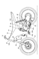
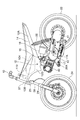
次に本発明の実施形態について説明する。図1は本発明に係わる自動二輪車の全体の左側面図を示し、図2は車体フレームの一部を切り欠いた左側面図を示している。 Next, an embodiment of the present invention will be described. FIG. 1 is a left side view of an entire motorcycle according to the present invention, and FIG. 2 is a left side view with a part of a body frame cut away.
符号40は単気筒4サイクルエンジンユニットであり、これはVベルト式無段変速装置が内蔵された伝達ユニット41と一体になってユニットスイング機構42を構成している。符号24は前輪を示し、前輪を軸支するフロントフォーク28が、車体フレーム12の前端に固着されたヘッドパイプ27及びアンダーブラケット25によって、左右方向に回動可能に枢支されている。
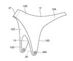
車体フレーム12は、図3の斜視図にも示すように、全体としては鞍状を成しており、かつ、車両の側面視(クランク軸方向視)から見て、略二股状に分岐形成されている。この二股の一方のフレームは車体後方側に向かってほぼ水平に延長されており、便宜上この部分を後部フレーム12Aと呼ぶ。
As shown in the perspective view of FIG. 3, the
後部フレーム12Aより車体前方側のフレーム部分を便宜上前部フレーム12Bと呼ぶ。図1及び図2に示すように、前部フレームはヘッドパイプ27の車体後方側近傍から始まり、後部フレームにつながっている。後部フレームの終端から前部フレームのハンドル近傍まで乗員が着座するためのシート14(図1及び図2)が置かれている。
A frame portion on the front side of the vehicle body from the
前部フレーム12Bと後部フレーム12Aとの境界領域から、車体下方にあるユニットスイングのエンジンユニット40に向い、かつ若干斜め後方に向かいながら垂下する垂下フレーム12Tが延長されている。この垂下フレームは、図3に示すように、車体の正面視から見て、エンジンユニットの両側をエンジンユニットのほぼ下端付近にまで延長しているサイドフレームユニット12Dと車体の正面方向に向いている正面フレームユニット12Cとから構成されている。
A drooping frame 12T extending from the boundary region between the
このサイドフレームユニット12Dの終端は、車体全長(前輪端から後輪端)のほぼ中心で地表より車輪のほぼ半径長分離れた地点にある。この延長した一対のサイドフレームユニットのほぼ終端にピポット軸26が貫通されており、このピポット軸が枢止点26Aとなって、ユニットスイング機構をフレーム12Dに揺動自在に支持している。
The end of the
ユニットスイング機構42は後輪22を支持するものでもあり、かつ、ユニットスイング機構は、車体フレーム12に緩衝機構(ダンパ)20を介して支持されている。
The
図3に示すように、車体前方側の正面側の正面フレームユニット12Cはエンジンユニット側に向けて垂下し、この途中に半楕円状の開口或いは切欠き15が設けられている。この開口からエンジンユニット40のシリンダヘッドがやや突出している(図1及び2参照)。
As shown in FIG. 3, the
図2に示すように、ユニットスイングのエンジンユニット側の下方、かつ側面からフランジ17がフレーム12Dから一体になって下方の枢止点26Aに向かって突出している。このフランジ17に前記ピポット軸26が圧入され、このピポット軸がゴムブッシュを介してエンジンユニット両側面のサイドフレームユニットの枢止点に支持されている。この枢止点は、エンジンユニットのクランク軸17Aの近傍かつ、車体前寄りでエンジンユニットのシリンダボディの下方に設定されている。この枢止点が既述のとおり車体のほぼ中心に設定されているために、ホイールベースが小さくなってもユニットスイング機構をコンパクトに配置することができる。既述のサイドフレームユニット12Dはこの枢止点に向けて配向されている。なお、後部フレーム12Aなどフレーム12の各部分は、鋳造などによって一体に成形されている。
As shown in FIG. 2, the
図1及び2に示すように、エンジンユニットは車体の側面視(クランク軸方向視)で前記開口部15(図3参照)に向かって斜め上方に延びており、エンジンユニットのシリンダヘッド部のほぼ終端が前記開口から車体前方方向側に突出している。車体の側面視で、フレームの車体下方に向かう正面フレームユニット12Cの端面は、ヘッドパイプから湾曲し、その後枢止点26Aに向かって連続的に傾斜している。したがって、車体の走行時に、走行風がフレーム12Cのラインに沿って枢止点側に下降し、開口部15からユニットスイング機構側に抜けることになる。したがって、従来の強制空冷のようなファンを回転させる特別な付加構造を備えることなく、エンジンのシリンダヘッドを自然空冷することが可能となる。なお、この枢止ン点26A付近では、車体両側のサイドフレームユニット12Dの一対同士が、クロスメンバによって連結されている。また、前サイドフレームユニット12Dには、エンジンメインテナンスの際のアクセスを容易にするために図1に示すような切欠き43が設けられている。この切欠きを介してサイドフレームから車体幅方向に隠れるエンジンユニット40に工具でアクセスすることが可能となる。この切欠きの代わりにサイドフレームに設けた孔部であって良い。なお、図1において、符号200は枢止点26A近傍のサイドフレーム12Dから車体外に突出したフートレストである。
As shown in FIGS. 1 and 2, the engine unit extends obliquely upward toward the opening 15 (see FIG. 3) in a side view of the vehicle body (as viewed in the crankshaft direction), and is substantially the same as the cylinder head portion of the engine unit. A terminal end projects from the opening toward the front side of the vehicle body. When viewed from the side of the vehicle body, the end surface of the
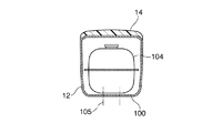
図4及び5は、前記フレーム12の車体幅方向の断面図を示すものであり、図4は、図2におけるA−A'断面図であり、図5が図2におけるB−B'断面図である。
4 and 5 are sectional views of the
図5に示すように、単一フレーム12の断面形状は、上部のみが開放された形状である、ほぼコの字状をなしており、フレーム上に前記シート14を載せることにより、その開放端が覆われている。符号104は燃料タンクであり、フレーム12内でその底面100にボルト105によって固定されている。フレームの開始端はヘッドパイプ27にあり、そのヘッド直後の単一フレームの部分は、図4に示すように、開放端がない天面102によって覆われている。この天面102には、孔110が形成されており、この開口からメインスイッチのキーシリンダ106が突出している。
As shown in FIG. 5, the cross-sectional shape of the
後部フレーム12Aでは、図6の横断面図に示すように、フレーム下面の両側から小リブ13Aが車体下方に向かって突出している。この小リブがある単一フレームの部分は後輪22上に存在することから、この小リブを泥除けとして用いることができる。
In the
なお、符号18は吸気装置であり、符号16は気化器である。また、符号29はフロントフォークに対する緩衝機構である。符号10はハンドグリップであり、その位置がステアリング軸(ヘッドパイプ軸)延長線より車体後方に設けてあることにより、ハンドルの操作性が良好になっている。まが、図1の符号200はフットレストである。
本発明のフレーム及びユニットスイング機構42により得られる自動二輪車のサイズ(車体長/前輪の前端から後輪の後端までの距離)は、1.6m以下、好適には1.5m前後の範囲である。
The size of the motorcycle (the length of the vehicle body / the distance from the front end of the front wheel to the rear end of the rear wheel) obtained by the frame and the
ここに説明した自動二輪車のユニットスイング機構42は車体フレーム12Dの枢止点26Aでゴムブッシュを介して揺動自在にピポット軸に支持されている。従来のリンク機構に対して防振性に優れ、かつコスト的にも有利である。
The motorcycle
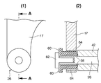
図8はゴムブッシュを用いたマウント機構の拡大図であり、(1)は車体フレームの端部の側面図、(2)は(1)のA−A側面図である。ユニットスイング機構42のフランジ17(図2参照)をピポット軸26が貫通している。ピポット軸26はT字型のゴムブッシュ60、外筒カラー64、及び内筒カラー68を介して車体フレーム12Dに嵌入されている。符号62は、ゴムブッシュ等からなる緩衝機構を軸26に固定するためのボルトである。ユニットスイング機構42はピポット軸を中心に回転する。ユニットスイングの揺動は緩衝機構によって緩衝されて車体フレーム12に伝達することが極力低減されている。
FIG. 8 is an enlarged view of a mounting mechanism using a rubber bush, (1) is a side view of the end portion of the vehicle body frame, and (2) is an AA side view of (1). The
12 車体フレーム、22 後輪、24 前輪、25 アンダーブラケット、26 ピポット軸、27 ヘッドパイプ、28 フロントフォーク、42 ユニットスイング機構
12 body frame, 22 rear wheel, 24 front wheel, 25 under bracket, 26 pivot shaft, 27 head pipe, 28 front fork, 42 unit swing mechanism
Claims (12)
The motorcycle according to claim 5, wherein the extension frame extends toward the vicinity of a crankshaft of the unit swing mechanism.
Priority Applications (1)
| Application Number | Priority Date | Filing Date | Title |
|---|---|---|---|
| JP2003403602A JP2005162000A (en) | 2003-12-02 | 2003-12-02 | Motorcycle |
Applications Claiming Priority (1)
| Application Number | Priority Date | Filing Date | Title |
|---|---|---|---|
| JP2003403602A JP2005162000A (en) | 2003-12-02 | 2003-12-02 | Motorcycle |
Publications (1)
| Publication Number | Publication Date |
|---|---|
| JP2005162000A true JP2005162000A (en) | 2005-06-23 |
Family
ID=34726866
Family Applications (1)
| Application Number | Title | Priority Date | Filing Date |
|---|---|---|---|
| JP2003403602A Pending JP2005162000A (en) | 2003-12-02 | 2003-12-02 | Motorcycle |
Country Status (1)
| Country | Link |
|---|---|
| JP (1) | JP2005162000A (en) |
Cited By (4)
| Publication number | Priority date | Publication date | Assignee | Title |
|---|---|---|---|---|
| JP2007326505A (en) * | 2006-06-09 | 2007-12-20 | Yamaha Motor Co Ltd | Motorcycle |
| JP2011079343A (en) * | 2009-10-02 | 2011-04-21 | Kawasaki Heavy Ind Ltd | Motorcycle |
| CN112623089A (en) * | 2020-12-31 | 2021-04-09 | 重庆黄河新能源汽车有限公司 | Integrated cast two-wheel vehicle frame |
| CN112693321A (en) * | 2020-12-31 | 2021-04-23 | 重庆黄河新能源汽车有限公司 | Mounting structure for mounting motor controller of electric vehicle on integrated casting frame |
-
2003
- 2003-12-02 JP JP2003403602A patent/JP2005162000A/en active Pending
Cited By (6)
| Publication number | Priority date | Publication date | Assignee | Title |
|---|---|---|---|---|
| JP2007326505A (en) * | 2006-06-09 | 2007-12-20 | Yamaha Motor Co Ltd | Motorcycle |
| JP2011079343A (en) * | 2009-10-02 | 2011-04-21 | Kawasaki Heavy Ind Ltd | Motorcycle |
| US8955637B2 (en) | 2009-10-02 | 2015-02-17 | Kawasaki Jukogyo Kabushiki Kaisha | Motorcycle having a swing arm suspended from a rear suspension via a link mechanism |
| CN112623089A (en) * | 2020-12-31 | 2021-04-09 | 重庆黄河新能源汽车有限公司 | Integrated cast two-wheel vehicle frame |
| CN112693321A (en) * | 2020-12-31 | 2021-04-23 | 重庆黄河新能源汽车有限公司 | Mounting structure for mounting motor controller of electric vehicle on integrated casting frame |
| CN112623089B (en) * | 2020-12-31 | 2025-08-12 | 重庆黄河新能源汽车有限公司 | Integrated casting formed two-wheel vehicle frame |
Similar Documents
| Publication | Publication Date | Title |
|---|---|---|
| KR100370671B1 (en) | Scooter type autobicycle | |
| JP2001328583A (en) | Rear wheel suspension for motorcycles | |
| JPWO2017033615A1 (en) | Power unit for saddle-ride type vehicles | |
| JP4070416B2 (en) | Step holder device for motorcycles | |
| JP2002284067A (en) | Pillion step holder structure for motorcycles | |
| JP6644820B2 (en) | Saddle-type vehicle | |
| JP4573745B2 (en) | Motorcycle with pillion step and mudguard | |
| JP2010076751A (en) | Motorcycle | |
| JP2002173071A (en) | Pillion step structure | |
| JP2005162001A (en) | Motorcycle | |
| JP2020060193A (en) | Saddle ride-type vehicle | |
| JP2006044633A (en) | Saddle riding vehicle | |
| JP3481050B2 (en) | Frame structure of scooter type vehicle | |
| JP2003182670A (en) | Leg shield structure of scooter type motorcycle | |
| KR20010020960A (en) | Scooter-typed vehicle | |
| JP2528623B2 (en) | Scooter type motorcycle equipped with a 4-cycle engine | |
| JP2013019383A (en) | Scooter type motorcycle | |
| JPS6037900Y2 (en) | Reaction unit cooling system for motorcycles | |
| JP5946367B2 (en) | Swing type power unit for saddle riding type vehicles | |
| JP2533766Y2 (en) | Vehicle with swing power unit | |
| JP2500565Y2 (en) | Cowling for vehicles such as motorcycles | |
| JP3564977B2 (en) | Motorcycle with unit swing type engine | |
| JP4421696B2 (en) | Motorcycle | |
| EP1366977B1 (en) | Exhaust muffler layout structure in motorcycle | |
| JP2003312564A (en) | Motorcycle handle switch mounting structure |
Legal Events
| Date | Code | Title | Description |
|---|---|---|---|
| A621 | Written request for application examination |
Free format text: JAPANESE INTERMEDIATE CODE: A621 Effective date: 20061011 |
|
| A977 | Report on retrieval |
Free format text: JAPANESE INTERMEDIATE CODE: A971007 Effective date: 20090319 |
|
| A131 | Notification of reasons for refusal |
Free format text: JAPANESE INTERMEDIATE CODE: A131 Effective date: 20090324 |
|
| A02 | Decision of refusal |
Free format text: JAPANESE INTERMEDIATE CODE: A02 Effective date: 20090715 |