JP2005173003A - Image forming apparatus - Google Patents
Image forming apparatus Download PDFInfo
- Publication number
- JP2005173003A JP2005173003A JP2003410326A JP2003410326A JP2005173003A JP 2005173003 A JP2005173003 A JP 2005173003A JP 2003410326 A JP2003410326 A JP 2003410326A JP 2003410326 A JP2003410326 A JP 2003410326A JP 2005173003 A JP2005173003 A JP 2005173003A
- Authority
- JP
- Japan
- Prior art keywords
- intermediate transfer
- drive
- driving
- photosensitive drum
- coupling
- Prior art date
- Legal status (The legal status is an assumption and is not a legal conclusion. Google has not performed a legal analysis and makes no representation as to the accuracy of the status listed.)
- Withdrawn
Links
Images


Landscapes
- Discharging, Photosensitive Material Shape In Electrophotography (AREA)
- Electrostatic Charge, Transfer And Separation In Electrography (AREA)
- Control Or Security For Electrophotography (AREA)
Abstract
【課題】 中間転写ベルトと感光ドラムの回転を開始する際に停止している感光ドラムに中間転写ベルトが摺擦して帯電メモリが発生し画像不良が発生するのを防止することを目的とする。
【解決手段】 感光ドラムを駆動するための駆動系に有するカップリングが駆動伝達解除状態にある時は、中間転写ベルトを駆動するための駆動系のカップリングが駆動伝達可能になるのを防止する部材を設ける。
【選択図】 図1
PROBLEM TO BE SOLVED: To prevent a charging memory from being generated due to sliding of an intermediate transfer belt against a photosensitive drum that is stopped when rotation of the intermediate transfer belt and the photosensitive drum is started, and an image defect is generated. .
When a coupling included in a drive system for driving a photosensitive drum is in a drive transmission release state, the coupling of the drive system for driving an intermediate transfer belt is prevented from being able to transmit the drive. A member is provided.
[Selection] Figure 1
Description
本発明は、プリンタ、複写機、ファクシミリ等の電子写真方式を採用した画像形成装置に関し、画像形成のための感光体および中間転写体を駆動するための駆動伝達手段に関する。 The present invention relates to an image forming apparatus employing an electrophotographic system such as a printer, a copying machine, and a facsimile, and relates to a drive transmission means for driving a photosensitive member and an intermediate transfer member for image formation.
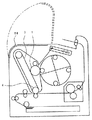
従来のカラー画像形成装置の一例として、ロータリー方式を用いたカラーLBPの概略断面を図9に示す。ロータリー方式のカラーLBPでは回転可能なロータリー部にイエロー・マゼンタ・シアン・ブラックのそれぞれ独立した4つの現像器を保持している。画像形成は一次帯電によって感光体(以下、感光ドラムと称す)表面を一様な電位とした後にレーザー光を照射して潜像を形成し、この潜像部に現像器からドラム表面にトナーが供給される。このドラム表面のトナー像を中間転写体(以下、中間転写ベルトと称す)に転写する。1つの現像器につき上記動作を行うことによって中間転写ベルト表面に一色のトナー像が形成される。次にロータリーを回転して2番目の現像器を感光ドラムに対する現像位置にし、同様の動作を行って2色目のトナー像が中間転写ベルト表面上に形成される。これを4回繰り返すことによって中間転写ベルト表面に4色のトナーが重ねられる。この中間転写ベルト表面に形成されたトナー像を転写材に転写し、定着手段によって転写材上のトナー像を転写材に固着させる。 As an example of a conventional color image forming apparatus, a schematic cross section of a color LBP using a rotary system is shown in FIG. In the rotary type color LBP, four independent developing units of yellow, magenta, cyan, and black are held in a rotatable rotary unit. In image formation, the surface of a photosensitive member (hereinafter referred to as a photosensitive drum) is uniformly charged by primary charging, and then a laser beam is irradiated to form a latent image. To this latent image portion, toner is transferred from the developing unit to the drum surface. Supplied. The toner image on the drum surface is transferred to an intermediate transfer member (hereinafter referred to as an intermediate transfer belt). By performing the above operation for each developing unit, a one-color toner image is formed on the surface of the intermediate transfer belt. Next, the rotary is rotated to bring the second developing unit into the developing position for the photosensitive drum, and the same operation is performed to form a second color toner image on the surface of the intermediate transfer belt. By repeating this four times, four color toners are superimposed on the surface of the intermediate transfer belt. The toner image formed on the surface of the intermediate transfer belt is transferred to a transfer material, and the toner image on the transfer material is fixed to the transfer material by a fixing unit.
現像器、感光ドラム、中間転写ベルトはジャム処理や消耗品としての交換をするために、装置本体に対して着脱可能になっている。感光ドラムと中間転写ベルトは一つのカートリッジとして一体に保持されている。このカートリッジ内の感光ドラム、中間転写ベルトの駆動はそれぞれ装置本体からカップリングを介して駆動伝達される。感光ドラムの駆動は感光ドラムの一端に一体的に取り付けられたカップリングに装置本体側のカップリングが係合して駆動が伝達される。一方中間転写ベルトはベルト駆動ローラの一端に一体的に取り付けられたカップリングに装置本体側のカップリングが係合して回転駆動が伝達され、駆動ローラの外周面に巻きつけた中間転写ベルトが駆動される。これらの本体側のカップリングはカートリッジ着脱のために設けられた開閉カバーに連動し、開閉カバーを開けた時には装置本体側のカップリングが退避して駆動伝達を解除し、カートリッジ着脱可能になる。一方、装置本体にカートリッジを装着して開閉カバーを閉じた時には、退避していた本体側の2つのカップリングがカートリッジ側のカップリングへとそれぞれ付勢される。その後本体が有する駆動源を駆動した際に本体側の2つのカップリングが回転し、カートリッジ側のカップリングと位相が合った方が先に係合状態となって感光ドラムまたは中間転写ベルトに駆動が伝達される。その後に他方のカップリングの位相が合った時に感光ドラムと中間転写ベルトの両方が駆動される。
しかしながら、上記従来例では感光ドラムと中間転写ベルトを駆動するためのカップリングがそれぞれ独立しているため、開閉カバーを閉じた後に駆動を開始して中間転写ベルトの駆動カップリングが先に係合し、その後に感光ドラム駆動のためのカップリングが係合することがある。この場合、中間転写ベルトのカップリングが係合してから感光ドラムのカップリングが係合するまでの間は、中間転写ベルトが走行し、感光ドラムは停止しているという状態になる。中間転写ベルトは感光ドラム表面に当接させているため、中間転写ベルトと当接している感光ドラム表面の回転方向一部分に走行している中間転写ベルトが摺擦して、この感光ドラム表面の一部分に摺擦による帯電メモリが発生する。この状態で画像形成をすると感光ドラム上に形成されるトナー像のうち、前記メモリが発生した部分の画像は濃度が変わってしまうという画像不良に至ることがあった。一方、感光ドラムのカップリングが中間転写ベルトのカップリングより先に係合して、停止している中間転写ベルトに対し感光ドラムが回転した場合には、中間転写ベルトの一部分に帯電メモリが発生する。しかし、感光ドラムの帯電メモリと比較すると画像上に現れる濃度変化は僅かであり、画像不良問題には至らない。 However, in the above conventional example, the coupling for driving the photosensitive drum and the intermediate transfer belt is independent of each other. Therefore, the drive is started after the opening / closing cover is closed, and the drive coupling of the intermediate transfer belt is engaged first. Thereafter, a coupling for driving the photosensitive drum may be engaged. In this case, during the period from when the coupling of the intermediate transfer belt is engaged until the coupling of the photosensitive drum is engaged, the intermediate transfer belt is running and the photosensitive drum is stopped. Since the intermediate transfer belt is in contact with the surface of the photosensitive drum, the intermediate transfer belt running in a part of the rotation direction of the surface of the photosensitive drum in contact with the intermediate transfer belt is rubbed and a part of the surface of the photosensitive drum is rubbed. A charging memory is generated by rubbing. When the image is formed in this state, the image of the portion where the memory is generated in the toner image formed on the photosensitive drum may cause an image defect in which the density changes. On the other hand, if the photosensitive drum is rotated with respect to the stopped intermediate transfer belt because the coupling of the photosensitive drum is engaged before the coupling of the intermediate transfer belt, a charging memory is generated in a part of the intermediate transfer belt. To do. However, the density change that appears on the image is slight compared with the charging memory of the photosensitive drum, which does not lead to an image defect problem.
本発明は大きく構成変更することなく、停止している感光ドラムに対して中間転写ベルトが走行して上記画像不良が発生するのを防止することが目的である。 SUMMARY OF THE INVENTION An object of the present invention is to prevent the occurrence of the above-mentioned image defect due to the intermediate transfer belt running on a stopped photosensitive drum without greatly changing the configuration.
前述の課題を解決するため本発明の画像形成装置では、中間転写ベルトと感光ドラムの2つのカップリングが共に退避した状態から係合状態にする際に、感光ドラムのカップリングが係合していない時には中間転写ベルトのカップリングを係合できない位置に維持するための部材を設けたことを特徴とする。 In order to solve the above-described problems, in the image forming apparatus of the present invention, the coupling of the photosensitive drum is engaged when the two couplings of the intermediate transfer belt and the photosensitive drum are brought into the engaged state from the retracted state. A member for maintaining the coupling of the intermediate transfer belt at a position where it cannot be engaged when not present is provided.
以上説明したように本願に記載した発明によれば、感光ドラムと中間転写ベルトの駆動をスタートしたときに、感光ドラムが停止した状態で中間転写ベルトが駆動されることがなくなり、感光ドラム表面の回転方向の一部に摺擦による帯電が発生しない。よって、感光ドラムの摺擦帯電による画像不良の発生がなくなる。 As described above, according to the invention described in the present application, when the driving of the photosensitive drum and the intermediate transfer belt is started, the intermediate transfer belt is not driven in a state where the photosensitive drum is stopped. Charging due to rubbing does not occur in a part of the rotation direction. Therefore, the occurrence of image defects due to frictional charging of the photosensitive drum is eliminated.
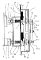
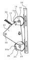
図1および図2は本発明の特徴を最も良く表す図面であり、同図を用いて各部の説明をする。 FIG. 1 and FIG. 2 are drawings that best illustrate the features of the present invention.
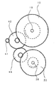
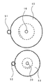
図1は感光ドラムおよび中間転写ベルトに駆動を伝達するカップリング機構を示している。図2は図1を右側面から見た図でカップリングに関わる部品のみを示した図ある。1は感光ドラム、2は感光ドラムの一端に固定されたドラムカップリング、3は中間転写ベルト、4は中間転写ベルトを駆動するためのベルト駆動ローラ、5はベルト駆動ローラの一端に固定された駆動ローラカップリングである。10は感光ドラム1を駆動するための回転可能に支持された軸、20はベルト駆動ローラ4を駆動するための回転可能に支持された軸で、それぞれの軸端部にはドラムカップリング2及び駆動ローラカップリング5の溝部に係合して回転を伝達するためのピン11及び12を有する。また、軸10及び20にはそれぞれギア12及び22を軸に対して固定的に配置し、不図示の駆動源からギア列を介してそれぞれのギア12、22に駆動が伝達されて軸が回転する。13及び23は軸10及び20に回転可能で軸方向へは移動不可能に支持されたピニオン、30は感光ドラム1や中間転写ベルト3を保持したカートリッジを着脱する際に開閉する装置本体の上カバーの動きに連動して上下するラックである。ピニオン13及び23はラック30と噛み合っており、装置本体の開閉カバーを開閉することでその回転位置が決まる。15及び25は圧縮バネで、軸10及び20に固定されたリングとフレームの間に配置し、軸10及び20をドラムカップリング2及び駆動ローラカップリング5に向けて付勢している。31は側板7に固定された軸32に揺動可能に支持されたロック部材で、引っ張りバネ33によって図2の反時計回り方向へ付勢されている。
FIG. 1 shows a coupling mechanism for transmitting drive to the photosensitive drum and the intermediate transfer belt. FIG. 2 is a view of FIG. 1 as viewed from the right side, and shows only components related to coupling. 1 is a photosensitive drum, 2 is a drum coupling fixed to one end of the photosensitive drum, 3 is an intermediate transfer belt, 4 is a belt driving roller for driving the intermediate transfer belt, and 5 is fixed to one end of the belt driving roller. Drive roller coupling.
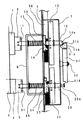
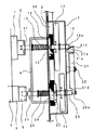
次に図1から図6を用いてカップリングについて説明する。図1及び図2は装置本体のカバーを開けてラック30が上昇し軸10及び軸20が感光ドラム1及びベルト駆動ローラ4から離れる方向へ退避して駆動伝達が解除されてカートリッジ着脱可能な状態を示し、図3及び図4はカバーを閉じてラック30が下降し軸10及び軸20が感光ドラム1及びベルト駆動ローラ4側に付勢されてピン11及び21がカップリング2及び5に係合して駆動伝達可能な状態を示している。図5及び図6は画像形成可能な図3,4の状態からカバーを開ける途中の状態を示している。
Next, the coupling will be described with reference to FIGS. 1 and 2 show a state in which the cover of the apparatus main body is opened, the
図3及び図4で示すカバーを閉じた状態ではラック30が下降した位置にあり、このときのピニオン13及び23の回転方向は図4に示す位置で、ピニオンの爪部13a及び23aは側板7に固定されたカム14及び24に当たらないので、軸10及び20はバネ15及び25によって感光ドラム1及びベルト駆動ローラ4側に付勢され、ピン11及び21がそれぞれカップリング2及び5の溝に係止されて回転駆動が伝達される。引っ張りバネ33によって反時計回り方向へ付勢されているロック部材31は突き当て面31aが軸10に当接した状態にある。このときロック部材31の爪部31aは軸20から退避した位置にあって軸20の移動規制はしない。
When the cover shown in FIGS. 3 and 4 is closed, the
図1及び図2で示すカバーを開けた状態ではラック30が上昇した位置にあり、このときのピニオン13及び23の回転方向はカバーを閉じた時のピニオンの位置に対して反時計回り方向に100度回転した位置となる。この位置ではピニオンの爪部13a及び23aがカム14及び24に当接して軸10及び20が図1に示すように右方向に移動する。よって軸10及び20がカップリング2及び5から離れてカートリッジの着脱が可能になる。ロック部材31は図1に示すように軸10が右方向に位置することでロック部材の端部31cが規制される。これによって図4に示すロック部材に対して揺動軸32を揺動中心として時計回り方向へ回転した位置にある。この位置では中間転写ベルト駆動のための軸20側に位置するロック部材31の爪部31dが軸20の溝部20aに係合し、軸20は駆動ローラカップリング5に向けて左方向へ移動できない状態にある。
When the cover shown in FIGS. 1 and 2 is opened, the
図5及び図6は図3,4に示すカバーを閉じた状態から半分だけ開けた状態を示している。このときピニオン13及び23はカバーを閉じた状態から反時計回り方向へ50度回転した位置にある。ドラム1を駆動するための軸10に支持されたピニオン13の爪部13aはカム14の斜面に当接し始める位置で、この段階では駆動伝達のためのカップリングは係合位置にある。一方中間転写ベルト駆動ローラ4を駆動するための軸20に支持されたピニオン23の爪部23aはカム24の斜面に沿って右方向へ移動完了した位置となる。よって、軸20が右方向へ移動し中間転写ベルト駆動ローラのカップリング5から軸20が退避して駆動伝達は解除状態になる。ロック部材31は軸10が図3,4に示す位置と同じであるためロック部材の爪部31dが軸20の移動規制しない位置にある。
5 and 6 show a state in which the cover shown in FIGS. 3 and 4 is half opened from the closed state. At this time, the
上記図5,6のカバー半開きの位置からカバーをさらに閉じるとピニオン13が回転しカム14の斜面に沿って軸10がカップリング部から離れる方向へ移動し、この軸先端10aがロック部材の端部斜面31bを押してロック部材31は時計回り方向へ回転する。これによってロック部材の爪部31dが軸20の溝部20aに係止され、軸20の軸方向への移動が規制された状態になる。
When the cover is further closed from the cover half-open position shown in FIGS. 5 and 6, the
以上の説明をもとにカバーを開いた状態からカバーを閉めてカップリングが結合するときの動きを説明する。先ずカバーが開いた状態では上記説明のとおり軸10及び20は感光ドラム1及び中間転写ベルト駆動ローラ5から離れる方向へ退避している。ロック部材31は軸10によって位置を規制され、爪31dが軸20の溝に係止されて軸20の軸方向の移動ができない。カバーを閉じるとピニオン13はカム14での規制が解除されて軸はカップリング側への移動が可能になり、軸10上のピン11とドラムカップリング2の溝の位相が合えば駆動伝達可能状態に移動できる。一方、ピニオン23はカバーが閉じられることでカム24からの規制が解除されるが、軸10が感光ドラム1へ駆動伝達可能なカップリング位置へと移動していない場合にはロック部材31の爪部31dが軸の溝20aに係合しているために駆動ローラカップリング5との係合ができない。つまり、カバーを閉じてギアを駆動スタートしてから、感光ドラムカップリングが係合した後でなければ中間転写ベルト駆動ローラのカップリングは係合できない。よって、駆動スタート後に停止している感光ドラムに対して中間転写ベルトが先に動き出すことはない。
Based on the above description, the movement when the coupling is coupled by closing the cover from the opened state will be described. First, when the cover is opened, the
他の実施例について説明する。図7は図1から6に示すロック部材を用いたときの一つの駆動源からギア12及び22に回転駆動を伝達するためのギア列を示している。この場合駆動源であるモータの軸に固定されたギア41が第一の段ギア42と噛み合い、第一の段ギア42と感光ドラムカップリングに駆動伝達する軸10上のギア12が噛み合って駆動が伝わる。中間転写ベルト駆動ローラに駆動伝達する軸20上のギア22は第一の段ギア42に噛み合う第二の段ギア43を介して駆動が伝達される。一方、他の実施例では図8に示すようにギア12とギア22のそれぞれに専用の駆動源51と52を設けて独立して回転駆動可能にしている。これによればギア51を先に回転スタートし、必ずカップリングが係合完了する角度以上回転した後に駆動源52を回転スタートする。これによって停止している感光ドラムに対して中間転写ベルトが先に動き出すことはない。
Another embodiment will be described. FIG. 7 shows a gear train for transmitting rotational drive from one drive source to the
1 感光ドラム
2 ドラムカップリング
3 中間転写ベルト
4 転写ベルト駆動ローラ
5 駆動ローラカップリング
10 感光ドラム駆動軸
20 駆動ローラ駆動軸
30 ロック部材
DESCRIPTION OF
Claims (3)
In an image forming apparatus that forms a toner image on a photosensitive member, transfers the toner image to an intermediate transfer member, and further transfers the toner image from the intermediate transfer member to a transfer material, a driving system for driving the photosensitive member and the intermediate transfer member are provided. Each drive system has a drive source, each drive system has drive transmission canceling means, and the photosensitive member is first driven at the start of driving after canceling the transmission of the two drive systems. An image forming apparatus, wherein only a driving source is activated and a driving source for driving an intermediate transfer member is activated after a predetermined time.
Priority Applications (1)
| Application Number | Priority Date | Filing Date | Title |
|---|---|---|---|
| JP2003410326A JP2005173003A (en) | 2003-12-09 | 2003-12-09 | Image forming apparatus |
Applications Claiming Priority (1)
| Application Number | Priority Date | Filing Date | Title |
|---|---|---|---|
| JP2003410326A JP2005173003A (en) | 2003-12-09 | 2003-12-09 | Image forming apparatus |
Publications (1)
| Publication Number | Publication Date |
|---|---|
| JP2005173003A true JP2005173003A (en) | 2005-06-30 |
Family
ID=34731442
Family Applications (1)
| Application Number | Title | Priority Date | Filing Date |
|---|---|---|---|
| JP2003410326A Withdrawn JP2005173003A (en) | 2003-12-09 | 2003-12-09 | Image forming apparatus |
Country Status (1)
| Country | Link |
|---|---|
| JP (1) | JP2005173003A (en) |
Cited By (2)
| Publication number | Priority date | Publication date | Assignee | Title |
|---|---|---|---|---|
| JP2009204950A (en) * | 2008-02-28 | 2009-09-10 | Fuji Xerox Co Ltd | Image forming apparatus |
| US7894737B2 (en) | 2008-09-29 | 2011-02-22 | Brother Kogyo Kabushiki Kaisha | Image-forming device |
-
2003
- 2003-12-09 JP JP2003410326A patent/JP2005173003A/en not_active Withdrawn
Cited By (2)
| Publication number | Priority date | Publication date | Assignee | Title |
|---|---|---|---|---|
| JP2009204950A (en) * | 2008-02-28 | 2009-09-10 | Fuji Xerox Co Ltd | Image forming apparatus |
| US7894737B2 (en) | 2008-09-29 | 2011-02-22 | Brother Kogyo Kabushiki Kaisha | Image-forming device |
Similar Documents
| Publication | Publication Date | Title |
|---|---|---|
| JP4444999B2 (en) | Developing device, process cartridge, and electrophotographic image forming apparatus | |
| JP4912381B2 (en) | Drive transmission device and image forming apparatus | |
| JP7081018B2 (en) | Drive transmission device and image forming device | |
| KR101733802B1 (en) | Development cartridge and electrophotographic image forming apparatus using the same | |
| EP1993000B1 (en) | Color electrophotographic image forming apparatus | |
| JP4267052B2 (en) | Color electrophotographic image forming apparatus | |
| EP3462247B1 (en) | Image forming apparatus | |
| JP2010033085A (en) | Developing device, process cartridge and electrophotographic image forming apparatus | |
| US11106160B2 (en) | Drive transmission device and image forming apparatus including the drive transmission device | |
| US11144006B2 (en) | Image forming apparatus | |
| JPH11338211A (en) | Image forming device | |
| JP2005173003A (en) | Image forming apparatus | |
| KR101739382B1 (en) | development cartridge and electrophotographic image forming apparatus using the same | |
| JP2005331548A (en) | Coupling device and image forming apparatus | |
| JP5202162B2 (en) | Image forming apparatus | |
| JP6632408B2 (en) | Drive transmission device and image forming apparatus | |
| JP2005148089A (en) | Image forming apparatus | |
| JP4016589B2 (en) | Image forming apparatus | |
| US8670695B2 (en) | Image forming apparatus | |
| US20210041824A1 (en) | Driving device and image forming apparatus |
Legal Events
| Date | Code | Title | Description |
|---|---|---|---|
| A300 | Withdrawal of application because of no request for examination |
Free format text: JAPANESE INTERMEDIATE CODE: A300 Effective date: 20070306 |