JP2005180902A - Boiler device - Google Patents
Boiler device Download PDFInfo
- Publication number
- JP2005180902A JP2005180902A JP2004096002A JP2004096002A JP2005180902A JP 2005180902 A JP2005180902 A JP 2005180902A JP 2004096002 A JP2004096002 A JP 2004096002A JP 2004096002 A JP2004096002 A JP 2004096002A JP 2005180902 A JP2005180902 A JP 2005180902A
- Authority
- JP
- Japan
- Prior art keywords
- wall
- vertical
- furnace wall
- boiler
- furnace
- Prior art date
- Legal status (The legal status is an assumption and is not a legal conclusion. Google has not performed a legal analysis and makes no representation as to the accuracy of the status listed.)
- Granted
Links
- 230000000452 restraining effect Effects 0.000 claims description 5
- 239000012528 membrane Substances 0.000 description 13
- 238000010586 diagram Methods 0.000 description 8
- 238000010248 power generation Methods 0.000 description 5
- 229910000831 Steel Inorganic materials 0.000 description 3
- 238000010521 absorption reaction Methods 0.000 description 3
- 230000005540 biological transmission Effects 0.000 description 3
- 239000010959 steel Substances 0.000 description 3
- 238000002485 combustion reaction Methods 0.000 description 2
- 239000002131 composite material Substances 0.000 description 2
- 238000003466 welding Methods 0.000 description 2
- 230000007423 decrease Effects 0.000 description 1
- 239000000446 fuel Substances 0.000 description 1
- 239000000463 material Substances 0.000 description 1
- 239000000725 suspension Substances 0.000 description 1
- 230000009466 transformation Effects 0.000 description 1
Images





Landscapes
- Fluidized-Bed Combustion And Resonant Combustion (AREA)
Abstract
Description
本発明は大容量火力発電用ボイラなどのボイラ装置に係り、特に炉壁の質量支持構造に関するものである。 The present invention relates to a boiler apparatus such as a boiler for large-capacity thermal power generation, and more particularly to a mass support structure for a furnace wall.
最新の大容量火力発電用ボイラにおいては、ボイラ火炉壁(以下、単に炉壁と称することがある)での熱吸収を炉壁出口で均一化するため、螺旋状のスパイラルメンブレン壁を採用している。すなわち従来のボイラでは全高さ方向に垂直管からなる炉壁を設けていたが、炉壁の周方向に生じた熱吸収のアンバランスが炉壁の高さ方向で増大するため、炉壁の焼損、変形などの問題が生じることがある。 In the latest large-capacity thermal power generation boilers, a spiral spiral membrane wall is used to equalize heat absorption in the boiler furnace wall (hereinafter sometimes referred to simply as the furnace wall) at the furnace wall outlet. Yes. In other words, in the conventional boiler, the furnace wall consisting of vertical pipes was provided in the entire height direction, but the unbalance of heat absorption generated in the circumferential direction of the furnace wall increased in the height direction of the furnace wall. Problems such as deformation may occur.
このため特にアンバランスが生じ易い下部の炉壁については、管方向が火炉の高さ方向に対して斜めに配置されるようにスパイラル状に配置することとして、下部炉壁にはスパイラル壁、上部炉壁には垂直壁を設けた構造が採用されるようになった。 For this reason, the lower furnace wall, which is particularly prone to unbalance, is arranged in a spiral shape so that the tube direction is inclined with respect to the height direction of the furnace. A structure with a vertical wall has been adopted for the furnace wall.
なお炉壁は鋼管と平鋼とが交互に隅肉溶接によりパネル状に形成された、所謂、メンブレン壁となっている。また炉壁内では燃焼が行われるため、炉内圧による幅方向の変形防止対策に加えて、熱伸びによる炉の高さ方向の熱伸び吸収対策が必要であることから、炉壁の全高さ方向に渡って炉壁の水平方向にはホリゾンタルバックステと呼ばれるサポート部材を炉壁と離間して設けて、炉壁としての剛性を確保しつつ熱伸びに対応する構造としている。 The furnace wall is a so-called membrane wall in which steel pipes and flat steel are alternately formed into a panel shape by fillet welding. In addition, since combustion occurs in the furnace wall, in addition to measures to prevent deformation in the width direction due to the furnace pressure, it is necessary to take measures to absorb heat elongation in the height direction of the furnace due to thermal elongation. In the horizontal direction of the furnace wall, a support member called a horizontal backsteer is provided apart from the furnace wall to ensure the rigidity as the furnace wall and to cope with thermal expansion.
図10に本発明が適用されるボイラ装置の概略斜視図を示す。また図7に本発明が適用される上部炉壁による下部炉壁の支持構造を示す。 FIG. 10 shows a schematic perspective view of a boiler apparatus to which the present invention is applied. FIG. 7 shows a support structure of the lower furnace wall by the upper furnace wall to which the present invention is applied.
ボイラ本体は図示していない鉄骨柱及び梁からなるボイラ建屋と呼ばれる構造体内の天井大梁に吊り下げられて設置されているが、この場合、垂直管からなる炉壁に比べてスパイラル管からなる炉壁は管の横断方向に壁の質量を負担することになるため、その部分的に負担可能な質量が制限される。このためスパイラル管からなる下部炉壁24に対してはバーチカルストラップ3と呼ばれる吊り部材を高さ方向に複数、炉壁の全周にわたって、一方の支点を垂直管からなる上部炉壁15に設け、他方の支点を下部炉壁24全体に分散して設けることにより、下部炉壁24の部分的な質量負担を軽減している。
The boiler body is hung from a ceiling ceiling beam in a structure called a boiler building consisting of steel columns and beams (not shown), but in this case, a furnace consisting of a spiral tube compared to a furnace wall consisting of a vertical tube Since the wall bears the mass of the wall in the transverse direction of the tube, the mass that can be partially burdened is limited. For this reason, a plurality of suspension members called
また、前記ホリゾンタルバックステ5が炉壁の水平方向に複数、炉壁を取り囲んで配置されているため、この質量も負担する必要があるが、この質量についてはメジャーリンク6と呼ばれるサポート部材を介し、ボイラ全周の高さ方向に複数配置された前記バーチカルストラップ3へ伝達され、さらに上部炉壁の垂直管に伝える構造になっている。すなわち前記バーチカルストラップ3により、下部炉壁24、ホリゾンタルバックステ5およびホリゾンタルバックステ5と前記バーチカルストラップ3とを接続する部材などの質量が、上部炉壁15に伝達される構造となっている。
In addition, since the
図7において、図中の1は火炉壁のうちの垂直壁からなる上部炉壁15を構成する垂直管、2はその垂直管1に接続されてスパイラルメンブレン壁からなる下部炉壁24を構成するスパイラル管、3はスパイラルメンブレン壁からなる下部炉壁24の全周にわたって垂直方向に配置され、前記垂直壁からなる上部炉壁15に支点を設けた多数のバーチカルストラップ、4はバーチカルストラップ3と平行に配置されたバーチカルバックステ−、5はスパイラルメンブレン壁からなる下部炉壁24の水平方向に配置された多数のホリゾンタルバックステ−、6はパーチカルストラップ3とホリゾンタルバックステ−5の間に配置されたメジャーリンク、7はパーチカルストラップ3とバーチカルバックステ−4の間に設けられたマイナーリンク、12はサポートピン、13はサポート、14はコーナリンクである。
In FIG. 7, reference numeral 1 in the figure denotes a vertical pipe constituting an
前述のように垂直管1に比べてスパイラル管2はその負担質量が制限されるため、バックステー4,5等の質量はメジャーリンク6を介して、バーチカルストラップ3へ伝達され、その質量はさらにバーチカルストラップ3を介して垂直管1に伝達される構造になっている。
As described above, since the burden mass of the
図8は、従来のボイラ装置におけるスパイラルメンブレン壁支持構造でのメジャーリンク6の配置状態を示す図である。本図は火炉側壁25における支持構造の配置状況を示しており、図中の一点鎖線8は火炉前壁、一点鎖線9は火炉後壁を示している。同図に示すように炉壁の垂直方向に多数配置されたバーチカルストラップ3と、炉壁の水平方向に多数配置されたホリゾンタルバックステ−5の各交差部またはその近傍にそれぞれメジャーリンク6を設け、各メジャーリンク6により、バーチカルストラップ3とホリゾンタルバックステ−5の全ての交差部を機械的に連結固定することにより、ホリゾンタルバックステ−5の剛性を確保して炉内圧などにより幅方向に変形するのを防止する。また熱伸びに対しては、高さ方向のホリゾンタルバックステ−5間にはメジャーリンク6により連結固定する代わりにマイナーリンク7を接続して、剛性を緩和し、熱伸びに追従する構造としていた。
FIG. 8 is a view showing an arrangement state of the
図9はボイラ装置の概略構成図、図10はボイラ装置の概略斜視図である。図中の10はホッパー壁で、図10に示すようにスパイラル管2で構成されている。11a,11bは火炉の上部、すなわちホッパー壁10のはるか上方の火炉天井部に吊り下げられた過熱器である。
FIG. 9 is a schematic configuration diagram of the boiler device, and FIG. 10 is a schematic perspective view of the boiler device.
図11は、ホッパー壁10の支持構造を示す斜視図である。この図に示されているように、ホッパー壁10の支持構造の場合には、ホッパー壁10が火炉底部のクリンカ排出部となっているため、ホッパー壁10に相当する火炉前壁及び火炉後壁が炉の内側に向かって傾いており、このためホッパー壁10の上方に設けた炉壁とは熱伸びの方向が変わるため、バーチカルストラップ3は図7の場合のように上部の炉壁側とは連結せずにホッパー壁10内に配置した構造としている。
FIG. 11 is a perspective view showing a support structure of the
また火炉側壁は傾いてはいないものの前記火炉前、後壁と合わせての全体調整が必要であるため、前記と同様にバーチカルストラップ3はホッパー壁10の真上の炉壁とは切り離して設けている。また側壁では特に断面積が縮小していることで、炉底に向けて本数を減らした配置としている。
Further, although the furnace side wall is not inclined, it is necessary to make an overall adjustment together with the front and rear walls of the furnace, so that the
図9に示すようにホッパー壁10は、それ自体の自重20に加えて、ホッパー壁10の上部の炉壁と同様にボイラ装置の運転時に炉圧16を受ける。さらにホッパー壁10は、過熱器11a,11bに付着したクリンカー17が落下したときに衝撃力18を受ける。また燃料の燃焼によって生じた灰19がホッパー壁10上に堆積すると、その重量がホッパー壁10に掛かる。このようにホッパー壁10は、それ自体の自重20、炉圧16、クリンカー17の落下衝撃力18ならびに堆積した灰19の重量などによって膨らみや変形を生じる。
As shown in FIG. 9, the
図12は、炉圧16などの荷重の掛かり方とボイラ運転中のホッパー壁10の変形を模式的に示した図である。炉圧16などの荷重はホッパー壁10を介してパーチカルストラップ3、マイナーリンク7、バーチカルバックステ−4ならびにホリゾンタルバックステ−5に伝達される。
FIG. 12 is a diagram schematically showing how to apply a load such as the
従来のボイラ装置は、ホッパー壁10も図8と同様に各メジャーリンク6により、バーチカルストラップ3とホリゾンタルバックステ−5の全ての交差部を機械的に連結固定されていた。
In the conventional boiler apparatus, the
この種のボイラ装置に関しては、例えば下記に示す特許文献などを挙げることができる。
ところが実際には下部にスパイラル壁、上部に垂直壁を配置した大容量火力発電用ボイラにおいても、主に温度差に起因する熱伸び差のため、バックステーの質量が均一にバーチカルストラップへ伝達されないことが判明した。この負担質量の不均一性のため、バーチカルストラップ等のサポート部材、質量を支える上部垂直管へ過大な応力が発生するから、過剰設計となりがちで、また負担質量の不均一性が解消されない場合にはチューブリークにつながるといった問題がある。 However, even in a large-capacity thermal power generation boiler with a spiral wall at the bottom and a vertical wall at the top, the mass of the backstay is not uniformly transmitted to the vertical strap due to the difference in thermal expansion mainly due to the temperature difference. It has been found. Due to this non-uniformity of the burden mass, excessive stress is generated on the support member such as the vertical strap and the upper vertical tube that supports the mass, so it tends to be over-designed and the non-uniformity of the burden mass cannot be resolved. Has the problem of leading to tube leaks.
本発明の目的は、このような従来技術の欠点を解消し、バックステーの質量が均等にバーチカルストラップへ伝達できる、信頼性の高いボイラ装置を提供することにある。 An object of the present invention is to provide a highly reliable boiler apparatus that eliminates the drawbacks of the prior art and can transmit the mass of the backstay to the vertical strap evenly.
前記目的を達成するため本発明の第1の手段は、ボイラ炉壁の高さ方向に配置された複数のバーチカルストラップと、ボイラ炉壁の水平手方向に配置された複数のバックステーとを備え、前記バーチカルストラップとバックステーとの交差部をサポート部材で連結するボイラ装置において、
前記バーチカルストラップとバックステーとの交差部のうちの一部の交差部を前記サポート部材で連結しないで非拘束構造にしたことを特徴とするものである。
In order to achieve the above object, the first means of the present invention includes a plurality of vertical straps arranged in the height direction of the boiler furnace wall and a plurality of backstays arranged in the horizontal hand direction of the boiler furnace wall. In the boiler device for connecting the intersection of the vertical strap and the back stay with a support member,
A part of the intersecting portions of the vertical strap and the backstay is not connected by the support member to form an unconstrained structure.
本発明の第2の手段は前記第1の手段において、前記炉壁が、垂直管からなる上部炉壁に接続されたスパイラル管からなる下部炉壁からなり、前記下部炉壁およびバックステーの質量が前記サポート部材ならびにバーチカルストラップを介して前記垂直管からなる上部炉壁に伝達される構造にしたことを特徴とするものである。 According to a second means of the present invention, in the first means, the furnace wall comprises a lower furnace wall comprising a spiral tube connected to an upper furnace wall comprising a vertical tube, and the mass of the lower furnace wall and the backstay Is configured to be transmitted to the upper furnace wall made of the vertical pipe through the support member and a vertical strap.
本発明の第3の手段は前記第1の手段において、前記炉壁が、前記垂直管からなる上部炉壁に接続されたスパイラル管からなる下部炉壁と、該下部炉壁に接続されてボイラの底部に設けられたホッパー壁からなり、前記下部炉壁、前記ホッパー壁およびその両方の炉壁の水平方向に配置されたバックステーの質量とが、前記サポート部材ならびにバーチカルストラップを介して前記垂直管からなる上部炉壁に伝達される構造にしたことを特徴とするものである。 According to a third means of the present invention, in the first means, the furnace wall has a lower furnace wall made of a spiral tube connected to the upper furnace wall made of the vertical tube, and a boiler connected to the lower furnace wall. The lower furnace wall, the hopper wall and the mass of the back stay arranged in the horizontal direction of both of the furnace walls through the support member and a vertical strap. It is characterized in that it is structured to be transmitted to the upper furnace wall consisting of tubes.
本発明は前述のような構成になっており、バーチカルストラップ負担質量の均等化が図れ、サポート部材の最適設計が可能であり、なおかつチューブリークの可能性を削減することで、ボイラ装置の信頼性を向上することができる。 The present invention is configured as described above, can equalize the vertical strap burden mass, can be optimally designed for the support member, and reduce the possibility of tube leakage, thereby reducing the reliability of the boiler device. Can be improved.
次に本発明の実施形態を図面と共に説明する。図7に示すように、炉壁にスパイラルメンブレン壁を備えた大容量火力発電用ボイラにおいて、スパイラル管2は負担質量が制限されるため、バックステー4、5の質量はメジャーリンク6と呼ばれるサポート部材を介し、ボイラ全周に配置されたバーチカルストラップ3へ伝達され、最終的に上部炉壁の垂直管1に伝える構造としている。
Next, embodiments of the present invention will be described with reference to the drawings. As shown in FIG. 7, in a large capacity thermal power generation boiler having a spiral membrane wall on the furnace wall, the burden mass of the
しかし従来のボイラ装置では、炉壁の周方向に生じた熱吸収のためのアンバランスが炉壁の高さ方向で増大するため図9に示すように、下部炉壁をスパイラル壁として緩和することができたが、局部的なアンバランスは依然として存在する。特にボイラ起動時間の短縮が要求される近年においては、急速立ち上げのためアンバランスが増長する現象が発生した。 However, in the conventional boiler apparatus, since the unbalance for heat absorption generated in the circumferential direction of the furnace wall increases in the height direction of the furnace wall, the lower furnace wall is relaxed as a spiral wall as shown in FIG. However, local imbalances still exist. In particular, in recent years when it is required to shorten the boiler start-up time, a phenomenon has occurred in which imbalance increases due to rapid start-up.
このため従来は図8に示すように、各レベルにおいて全ストラップへメジャーリンク6を設置していたため、温度アンバランスに起因する熱伸び差が増大し、水平方向に配置されたホリゾンタルバックステ−5に対して同レベルまたは近傍に配置されたメジャーリンク6にレベル差が生じる現象が発生した。これによりバックステー4,5の質量を負担しないバーチカルストラップ3が発生した場合には、相対的に一部のバーチカルストラップ3へ過度の応力が生じ、メジャーリンク6の損傷及び最終的に質量を負担する上部垂直管1の損傷へ繋がる可能性がある。
For this reason, as shown in FIG. 8, conventionally, the measure links 6 are installed on all the straps at each level. Therefore, the difference in thermal expansion due to the temperature imbalance is increased, and the horizontal backstage 5 disposed in the horizontal direction is increased. On the other hand, a phenomenon occurs in which a level difference occurs in the
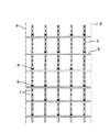
そこで本発明の第1実施形態では図1に示すように、スパイラルメンブレン壁を備えた大容量火力発電用ボイラにおいて、そのスパイラルメンブレン壁の垂直方向に配置されたバーチカルストラップ3と水平方向に配置されたホリゾンタルバックステ−5の各交差部の全てにメジャーリンク6を配置するのではなく、同図に示すようにメジャーリンク6を1つおきに千鳥に配置している。従って、交差部のメジャーリンク6が配置されていない所ではバーチカルストラップ3とホリゾンタルバックステ−5は機械的に連結されておらず、非拘束部となっている。よってこの第1実施形態ではメジャーリンク6と非拘束部が互いに1つおきに千鳥配列されていることになる。
Therefore, in the first embodiment of the present invention, as shown in FIG. 1, in a large capacity thermal power generation boiler having a spiral membrane wall, the
このように前記交差部に一部に非拘束部を設けることにより、炉壁の周方向に複数配置されたバーチカルストラップ3ヘ熱伸び差が発生した場合、質量を負担しないバーチカルストラップ3が発生することなく、全体的にストラップは均等な質量を負担することとなり、サポート部材の最適設計、及びチューブリークの可能性の低減を図ることが可能となる。
Thus, by providing a part of the non-restraining portion at the intersection, when a plurality of
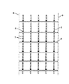
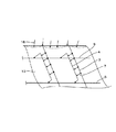
図2は本発明の第2実施形態を示す図、図3は本発明の第3実施形態を示す図、図4は本発明の第4実施形態を示す図で、各図に示すようにメジャーリンク6と非拘束部の配置状態がそれぞれ異なった実施形態を示している。なお、各実施形態において、メジャーリンク6と非拘束部の配置は一部に偏らないで、ボイラ全体から見てバランスよく配置することが必要である。
FIG. 2 is a diagram showing a second embodiment of the present invention, FIG. 3 is a diagram showing a third embodiment of the present invention, and FIG. 4 is a diagram showing a fourth embodiment of the present invention. The embodiment in which the arrangement state of the
このように非拘束部を設けるのは、火炉壁の一部を構成する垂直管からなる垂直壁15だけではなく、ホッパー壁10にも適用される。ホッパー壁10に適用した場合、ホッパー壁10においてもその外側に設置される支持構造は、図11に示すようにバーチカルストラップ3、マイナーリンク7、バーチカルバックステー4、ホリゾンタルバックステ−5などを有している。
The provision of the non-restraining portion in this way is applied not only to the
このバーチカルストラップ3は、ホッパー壁10に溶接で固定したサポート13とサポートピン12でホッパー壁10に取り付けられている。このバーチカルストラップ3は、前記下部炉壁に設けたものと同じ技術思想から設けているが、この他にホッパー壁10においてはホッパー壁10が受ける荷重、すなわち炉圧16、クリンカー17が落下した時に生じる衝撃力18、灰19の重量などに対応する必要もある。ホッパー壁10においては特に、従来の剛構造では衝撃力18を吸収できずに支持部材の変形、炉壁の損傷が起きる可能性が高いが、本発明のように一部に非拘束部を設けることにより、柔軟構造となり衝撃力に対応することが可能となる。
The
ホリゾンタルバックステ−5の上下面には、バーチカルバックステー4が設置されており、バーチカルバックステー4とバーチカルストラップ3の間にマイナーリンク7が介在されている。バーチカルストラップ3で受けた荷重は、マイナーリンク7を介してバーチカルバックステー4に伝達され、さらにその荷重はホリゾンタルバックステ−5、コーナリンク14を介してホッパー壁10によって支持される。
A
すなわちホッパー壁10に設けられた一連の支持構造は下部炉壁側のバーチカルストラップ3に連結して設けても良いが、ホッパー壁10が炉の内側に向かって形成されているため、連結部での熱伸び方向が異なることに起因して構造が複雑になること、火炉全体の炉壁の高さに対してホッパー壁10の高さが、例えば10%程度と少ないことから、ホッパー壁10全体を図11に示すようにコーナリンク14で一旦側壁で受けて、ホッパー壁10全体としては下部炉壁全体で質量負担することも可能である。
That is, a series of support structures provided on the
図5は、この荷重の伝達経路を模式的に示した図である。バーチカルストラップ3、マイナーリンク7、バーチカルバックステー4ならびにホリゾンタルバックステ−5は弾性体であり、それぞれのばね定数をK1,K2,K3ならびにK4とする。
FIG. 5 is a diagram schematically showing the load transmission path. The
バーチカルストラップ3とマイナーリンク7ならびにマイナーリンク7とバーチカルバックステー4の間はピンによって連結して、バーチカルストラップ3とマイナーリンク7ならびにマイナーリンク7とバーチカルバックステー4の間に、前記ピンの径とそのピンを挿入するピン孔の径の差によってギャップ21,22を設けている。図5中の符号23は炉内面である。
The
前述のようにマイナーリンク7の両端部にギャップ21,22を設けることにより、実際のばね定数(ばね特性)は図6で示す実線となり、ギャップ21,22に対応してばね定数は減少する。
By providing the
荷重の伝達経路上からはバーチカルストラップ3、マイナーリンク7、バーチカルバックステー4ならびにホリゾンタルバックステ−5は直列に配置されているから、これらの合成ばね定数Kは、
1/K=1/K1+1/K2+1/K3+1/K4
となる。
Since the
1 / K = 1 / K1 + 1 / K2 + 1 / K3 + 1 / K4
It becomes.
従って合成ばね定数は従来に比較して小さく設定でき、柔軟な構造となるから、これらが緩衝材として機能する。よってクリンカー17が落下したときに生じるホッパー壁10への衝撃力18が減少し、そのためにホッパー壁10の強度健全性を高めることができる。また、最終的には荷重を受けるホリゾンタルバックステ−5への衝撃力も低減でき、ボイラ装置の信頼性を向上することができる。
Accordingly, the composite spring constant can be set smaller than the conventional one, and the structure becomes flexible, so that these function as a cushioning material. Therefore, the impact force 18 to the
前記実施形態ではホッパー壁10がスパイラル管2で構成される場合を説明したが、垂直管でホッパー壁を構成するボイラ装置にも本発明は適用可能である。
Although the case where the
1:垂直管、2:スパイラル管、3:バーチカルストラップ、4:バーチカルバックステー、5:ホリゾンタルバックステー、6:メジャーリンク、7:マイナーリンク、8:火炉前壁、9:火炉後壁、10:ホッパー壁、11:過熱器、12:サポートピン、13:サポート、14:コーナリンク、15:垂直壁、16:炉圧、17:クリンカー、18:衝撃力、19:灰、20:ホッパー壁の自重、21,22:ギャップ、23:炉内面。 1: vertical pipe, 2: spiral pipe, 3: vertical strap, 4: vertical backstay, 5: horizontal backstay, 6: major link, 7: minor link, 8: front wall of furnace, 9: rear wall of furnace, 10 : Hopper wall, 11: superheater, 12: support pin, 13: support, 14: corner link, 15: vertical wall, 16: furnace pressure, 17: clinker, 18: impact force, 19: ash, 20: hopper wall Weight, 21, 22: gap, 23: furnace inner surface.
Claims (3)
前記バーチカルストラップとバックステーとの交差部のうちの一部の交差部を前記サポート部材で連結しないで非拘束構造にしたことを特徴とするボイラ装置。 A plurality of vertical straps arranged in the height direction of the boiler furnace wall and a plurality of back stays arranged in the horizontal hand direction of the boiler furnace wall, and a support member at the intersection of the vertical strap and the back stay In the boiler equipment to be connected,
A boiler device characterized in that a part of the intersecting portions of the vertical strap and the backstay is not connected by the support member and has a non-restraining structure.
2. The boiler apparatus according to claim 1, wherein the furnace wall is provided at a bottom furnace wall connected to the lower furnace wall and a lower furnace wall connected to the upper furnace wall consisting of the vertical pipe. An upper furnace wall comprising a hopper wall, and the mass of the lower furnace wall, the hopper wall and the back stay arranged in the horizontal direction of both the furnace walls, and the vertical pipe via the support member and a vertical strap. Boiler device characterized by having a structure transmitted to
Priority Applications (1)
| Application Number | Priority Date | Filing Date | Title |
|---|---|---|---|
| JP2004096002A JP4336231B2 (en) | 2003-11-28 | 2004-03-29 | Boiler equipment |
Applications Claiming Priority (2)
| Application Number | Priority Date | Filing Date | Title |
|---|---|---|---|
| JP2003399316 | 2003-11-28 | ||
| JP2004096002A JP4336231B2 (en) | 2003-11-28 | 2004-03-29 | Boiler equipment |
Publications (2)
| Publication Number | Publication Date |
|---|---|
| JP2005180902A true JP2005180902A (en) | 2005-07-07 |
| JP4336231B2 JP4336231B2 (en) | 2009-09-30 |
Family
ID=34797387
Family Applications (1)
| Application Number | Title | Priority Date | Filing Date |
|---|---|---|---|
| JP2004096002A Expired - Lifetime JP4336231B2 (en) | 2003-11-28 | 2004-03-29 | Boiler equipment |
Country Status (1)
| Country | Link |
|---|---|
| JP (1) | JP4336231B2 (en) |
-
2004
- 2004-03-29 JP JP2004096002A patent/JP4336231B2/en not_active Expired - Lifetime
Also Published As
| Publication number | Publication date |
|---|---|
| JP4336231B2 (en) | 2009-09-30 |
Similar Documents
| Publication | Publication Date | Title |
|---|---|---|
| JPH06101804A (en) | Spare stay system for connecting end section of tabular welded tube wall in boiler | |
| CN103415629B (en) | Hot blast branch pipe construction method and hot blast branch pipe of blast furnace hot blast stove | |
| KR20090008372A (en) | Cyclone separator arrangement for a fluidized bed boiler and mounting construction | |
| CN101627258B (en) | Method of and apparatus for supporting walls of a power boiler | |
| US7509928B2 (en) | Suspended steam boiler | |
| JP4336231B2 (en) | Boiler equipment | |
| KR0167634B1 (en) | Vertical buckstay/leveler attachment to a horizontal buckstay | |
| JP6122744B2 (en) | Seismic tie for boiler vibration control and boiler seismic structure using the same | |
| JP2011068971A (en) | Method for constructing hot-blast divided tube in hot-stove for blast furnace | |
| EP3704411B1 (en) | A boiler system with a support construction | |
| KR20150065833A (en) | Boiler structure and method of assembly | |
| JP7266586B2 (en) | boiler structure | |
| CN108884990B (en) | System and method for supporting boiler loads | |
| JP6514490B2 (en) | Internally reinforced high-life waste heat recovery boiler equipment | |
| TWI744815B (en) | Boiler plant | |
| EP0632136B1 (en) | Dome connecting structure of external combustion hot stove for blast furnace | |
| JP5347873B2 (en) | Hot air branch structure of a hot blast furnace | |
| JP4076014B2 (en) | Waste heat recovery boiler and its installation method | |
| JP7353463B2 (en) | Boiler equipment and boiler furnace wall reinforcement structure | |
| CN116438406B (en) | Supporting mechanism of waste heat recovery boiler | |
| JP5611678B2 (en) | Boiler equipment | |
| CN210320011U (en) | Heat insulation type cyclone separator central cylinder mounting structure | |
| CN211976846U (en) | Shockproof support sheath device for high-pressure superheater of waste heat boiler | |
| JPH03274303A (en) | Support stand for waste heat recovery type boiler | |
| JP2014129972A (en) | Heat transfer pipe assembly and heat recovery device having the same |
Legal Events
| Date | Code | Title | Description |
|---|---|---|---|
| A621 | Written request for application examination |
Free format text: JAPANESE INTERMEDIATE CODE: A621 Effective date: 20061207 |
|
| A977 | Report on retrieval |
Free format text: JAPANESE INTERMEDIATE CODE: A971007 Effective date: 20081022 |
|
| A131 | Notification of reasons for refusal |
Free format text: JAPANESE INTERMEDIATE CODE: A131 Effective date: 20081028 |
|
| A521 | Request for written amendment filed |
Free format text: JAPANESE INTERMEDIATE CODE: A523 Effective date: 20090105 |
|
| TRDD | Decision of grant or rejection written | ||
| A01 | Written decision to grant a patent or to grant a registration (utility model) |
Free format text: JAPANESE INTERMEDIATE CODE: A01 Effective date: 20090616 |
|
| A01 | Written decision to grant a patent or to grant a registration (utility model) |
Free format text: JAPANESE INTERMEDIATE CODE: A01 |
|
| A61 | First payment of annual fees (during grant procedure) |
Free format text: JAPANESE INTERMEDIATE CODE: A61 Effective date: 20090626 |
|
| FPAY | Renewal fee payment (event date is renewal date of database) |
Free format text: PAYMENT UNTIL: 20120703 Year of fee payment: 3 |
|
| R150 | Certificate of patent or registration of utility model |
Ref document number: 4336231 Country of ref document: JP Free format text: JAPANESE INTERMEDIATE CODE: R150 Free format text: JAPANESE INTERMEDIATE CODE: R150 |
|
| FPAY | Renewal fee payment (event date is renewal date of database) |
Free format text: PAYMENT UNTIL: 20130703 Year of fee payment: 4 |
|
| S111 | Request for change of ownership or part of ownership |
Free format text: JAPANESE INTERMEDIATE CODE: R313111 |
|
| R350 | Written notification of registration of transfer |
Free format text: JAPANESE INTERMEDIATE CODE: R350 |
|
| R250 | Receipt of annual fees |
Free format text: JAPANESE INTERMEDIATE CODE: R250 |
|
| EXPY | Cancellation because of completion of term |