JP2005190844A - Fluorescent lamps and lighting fixtures - Google Patents
Fluorescent lamps and lighting fixtures Download PDFInfo
- Publication number
- JP2005190844A JP2005190844A JP2003431224A JP2003431224A JP2005190844A JP 2005190844 A JP2005190844 A JP 2005190844A JP 2003431224 A JP2003431224 A JP 2003431224A JP 2003431224 A JP2003431224 A JP 2003431224A JP 2005190844 A JP2005190844 A JP 2005190844A
- Authority
- JP
- Japan
- Prior art keywords
- fluorescent lamp
- electrode
- stem
- lead wires
- bulb
- Prior art date
- Legal status (The legal status is an assumption and is not a legal conclusion. Google has not performed a legal analysis and makes no representation as to the accuracy of the status listed.)
- Pending
Links
Images
Landscapes
- Common Detailed Techniques For Electron Tubes Or Discharge Tubes (AREA)
- Non-Portable Lighting Devices Or Systems Thereof (AREA)
- Vessels And Coating Films For Discharge Lamps (AREA)
Abstract
【目的】一対の導入線間のステム上に飛散物が連続的に付着し一対の導入線間の短絡などに伴う異常放電の継続がなされたとしても、透光性放電容器が溶融、破損することを抑制することができる蛍光ランプを提供することにある。
【課題】バルブ内径(a)とフレアチューブ外径(b)はb/a>0.65以上であり、バルブ端部から電極側ステム端部までの長さは20mm以上であるので、万が一寿命末期に以上発熱し、ステムが溶融しても、溶融したステムから口金側へ熱伝導を低減させ、ランプの破損溶融を抑制することができる。
【選択図】図1[Purpose] Even if the scattered matter continuously adheres to the stem between a pair of lead wires and the abnormal discharge continues due to a short circuit between the pair of lead wires, the translucent discharge vessel melts and breaks. It is in providing the fluorescent lamp which can suppress this.
The valve inner diameter (a) and flare tube outer diameter (b) are b / a> 0.65 or more, and the length from the valve end to the electrode stem end is 20 mm or more. Even if heat is generated at the end stage and the stem is melted, heat conduction from the melted stem to the base side can be reduced, and breakage and melting of the lamp can be suppressed.
[Selection] Figure 1
Description
本発明は、高周波点灯される蛍光ランプの寿命末期に異常放電が継続した場合において、特にランプ端部の損壊を抑制した蛍光ランプおよび照明器具に関する。 The present invention relates to a fluorescent lamp and a luminaire that particularly suppress damage to the lamp end when abnormal discharge continues at the end of the life of a fluorescent lamp that is lit at high frequency.
一般に、熱陰極を備えた蛍光ランプを長期にわたり点灯すると、フィラメントを構成するタングステンなどの物質や、これに塗布した酸化バリウムなどの電子放射物質、およびフィラメントに近い導入線を構成するニッケルなどの導入線先端部材が飛散し損耗する。これら飛散物はバルブ壁に付着して、黒化を生じるとともに、フィラメントに近いステムの先端面にも付着して堆積する。特に、高周波点灯の場合は、相対的に高い電圧を印加するので、ランプの寿命末期にフィラメントの電子放射物質が飛散した後にランプが半波放電を起こすことがある。このような異常放電が生じるとフィラメント物質や導入線の物質の飛散が一層激しくなり、これらはフィラメントに近いフレアステムの先端面に付着しやすい。 In general, when a fluorescent lamp equipped with a hot cathode is turned on for a long period of time, a substance such as tungsten constituting the filament, an electron emitting substance such as barium oxide applied thereto, and nickel constituting an introduction line close to the filament are introduced. The wire tip member is scattered and worn out. These scattered matter adheres to the valve wall and causes blackening, and also adheres to and accumulates on the distal end surface of the stem close to the filament. In particular, in the case of high-frequency lighting, since a relatively high voltage is applied, the lamp may cause a half-wave discharge after the electron emission material of the filament is scattered at the end of the lamp life. When such an abnormal discharge occurs, the scattering of the filament material and the material of the lead-in wire becomes more intense, and these are likely to adhere to the tip surface of the flare stem close to the filament.
このような付着物は導電体であるから、ある程度堆積すると通電経路を形成する可能性がある。すなわち、フレアステム等一対の導入線を封止している封止部の先端面に電極飛散物などが堆積すると、この飛散物が一対の導入線の間に導電経路を形成してしまう。 Since such a deposit is a conductor, there is a possibility that an energization path will be formed if it is deposited to some extent. In other words, if scattered electrode or the like is deposited on the front end surface of the sealing portion that seals the pair of lead wires such as the flare stem, the scattered matter forms a conductive path between the pair of lead wires.
一般に、寿命末期にフィラメントが断線すると、蛍光ランプの点灯装置は発振を停止するように構成されているが、上記のように飛散物による堆積物の導電経路によって一対の導入線間が導通(短絡)している場合には、フィラメントが断線しても点灯装置は動作を継続するおそれがある。たとえば、蛍光ランプの点灯装置が一対のフィラメントの非電源側端子間に予熱コンデンサを接続したいわゆるコンデンサ予熱方式であって、正帰環制御するいわゆる自励発振形のインバータの場合、フィラメントが断線すると帰還制御されなくなるため発振が停止する。しかし、一対の導入線間に飛散物の堆積物によって導電経路が形成されている場合には、フィラメントが断線しても導電経路に電流が流れるので、帰還制御を維持することになり、点灯装置が発振を継続する。この場合、蛍光ランプは断線した一方のフィラメントが熱陰極として作用しないので、いわゆる半波放電を繰り返すことになって、異常放電による点灯が継続されることになる。また、この異常放電によって導電経路が発熱し、フレアステムが熱破損したり、導電経路に過大な電流が流れて大きな電力損失を生じる不具合がある。 In general, when the filament breaks at the end of the life, the fluorescent lamp lighting device is configured to stop oscillation, but as described above, the pair of lead wires are connected (short-circuited) by the conductive path of the deposit due to the scattered matter. If the filament is broken, the lighting device may continue to operate. For example, a fluorescent lamp lighting device is a so-called capacitor preheating method in which a preheating capacitor is connected between the non-power supply side terminals of a pair of filaments. Oscillation stops because feedback control is not performed. However, if a conductive path is formed between the pair of lead-in lines due to scattered deposits, a current flows through the conductive path even if the filament is disconnected, so feedback control is maintained, and the lighting device Continues to oscillate. In this case, since one broken filament of the fluorescent lamp does not act as a hot cathode, so-called half wave discharge is repeated, and lighting by abnormal discharge is continued. In addition, the abnormal discharge generates heat in the conductive path, causing the flare stem to be damaged by heat, or causing an excessive current to flow in the conductive path, resulting in a large power loss.
また、一般にフィラメントから電子放射物質が完全に飛散して枯渇した場合には不点となるが、インバータ点灯の場合は2次電圧が高いので、電子放射物質が完全に飛散して枯渇した後でも、半波放電を継続することがあり、このような場合も上記一対の導入線間に形成された導電経路に電流が流れて、この導電経路が発熱し、フレアステムが破損したり、過大な電流が流れて大きな電力損失を生じることがある。そこで、従来からこのような放電放射物質による一対の導入線間の短絡の防止を図った技術が提案されている(例えば、特許文献1参照)。
特許文献1の蛍光ランプは、寿命末期時にフィラメント電極のエミッタが消失し、電極部分の温度が上昇しても電極を保持する一対のリード線を封止しているステム表面に非導電性の耐熱性材料によって被覆しているものである。しかし、ガラスからなるステム表面に耐熱性材料により被覆ったとしても、電極部分の温度が上昇しつづけ、ステムが溶融を始めるとその耐熱性材料被膜の構造が破壊され、ステム溶融を抑制する作用が十分ではなく、ランプ損傷の問題を生じるおそれがある。 The fluorescent lamp of Patent Document 1 has a non-conductive heat-resistant surface on the stem surface that seals a pair of lead wires that hold the electrode even when the temperature of the electrode part rises and the temperature of the electrode part rises at the end of life. It is covered with a functional material. However, even if the stem surface made of glass is covered with a heat-resistant material, the temperature of the electrode part continues to rise, and when the stem begins to melt, the structure of the heat-resistant material coating is destroyed, and the stem melting action is suppressed. Is not sufficient and can cause lamp damage problems.
本発明の目的は、このような事情を考慮してなされたもので、その目的は、一対の導入線間のステム上に飛散物が連続的に付着し一対の導入線間の短絡などに伴う異常放電の継続がなされたとしても、透光性放電容器が溶融、破損することを抑制することができる蛍光ランプを提供することにある。 The object of the present invention has been made in view of such circumstances, and the object is accompanied by a short circuit between the pair of introduction lines due to the continuous adhering of scattered matter on the stem between the pair of introduction lines. An object of the present invention is to provide a fluorescent lamp capable of preventing the translucent discharge vessel from being melted and broken even if the abnormal discharge is continued.
請求項1記載の蛍光ランプは、内部に放電媒体が封入されるとともに、内面に蛍光体が塗布されたバルブと;フィラメント電極の両端部を支持する一対のリード線およびこのリード線を封着するステムを有し、前記バルブの少なくとも一端部に封装されたマウントと;内部空間に連続する前記バルブ端部を挿入する挿入孔が形成されており、電極から導出されたワイヤと電気的に接続される口金ピンを有する口金と;を具備しており、バルブ内径をaフレアチューブ外径をbとしたときb/a>0.65以上でありかつバルブ端部から電極側ステム端部までの長さは20mm以上であることを特徴とするものである。 The fluorescent lamp according to claim 1, wherein a discharge medium is sealed inside, a bulb having an inner surface coated with a phosphor, a pair of lead wires supporting both ends of the filament electrode, and the lead wires are sealed. A mount having a stem and sealed at least at one end of the bulb; and an insertion hole for inserting the bulb end continuous with the internal space is formed, and is electrically connected to a wire led out from the electrode A base having a base pin, and b / a> 0.65 or more when the valve inner diameter is a flare tube outer diameter b and the length from the valve end to the electrode stem end The thickness is 20 mm or more.
バルブは、例えば石英ガラスバルブからなり、ガラスバルブの内面側に形成した蛍光体層、およびガラスバルブ内に封入した放電媒体を備えて構成されている。しかしながら、バルブは、石英ガラスのほか、透光性セラミックなどであってもよい。特に蛍光ランプの寿命末期の異常発熱などにより溶融、破損しやすい材料の場合、本発明は有効である。 The bulb is made of, for example, a quartz glass bulb, and includes a phosphor layer formed on the inner surface side of the glass bulb and a discharge medium sealed in the glass bulb. However, the bulb may be translucent ceramic or the like in addition to quartz glass. In particular, the present invention is effective in the case of a material that is easily melted or damaged due to abnormal heat generation at the end of the life of a fluorescent lamp.
放電媒体は、例えば希ガスとしてアルゴン、ネオン、クリプトン、キセノンなどの不活性ガスおよび水銀からなるもが一般的だが、本発明においてはこれに限定されない。 The discharge medium is generally made of, for example, an inert gas such as argon, neon, krypton, or xenon as a rare gas and mercury, but is not limited to this in the present invention.
バルブの形状は、任意の形状を成していることができる。たとえば、直管、U字状、W字状、螺旋状などであることを許容する。 The shape of the valve can be any shape. For example, a straight pipe, a U shape, a W shape, a spiral shape, and the like are allowed.
一対の導入線は、ニッケルや鉄などを主体としたワイヤなどにより形成されている。このような導入線のうちバルブ内に存在する導入線は、電気抵抗が極めて低く、フィラメントとの抵抗差が小さい。これら導入線の内端部にフィラメントが掛け渡し支持されている。さらに、この導入線は、ステム、ピンチシールおよびビードガラスなどを用いてバルブの両端部に封装されるが、導入線の封止部材および封止方法などは特に限定されない。要するにバルブの内側に電極を形成するように導入線が封止され、一対の導入線間に封止端を形成する方法であればよい。 The pair of lead-in wires is formed of a wire mainly composed of nickel or iron. Of these lead wires, lead wires present in the bulb have an extremely low electrical resistance and a small resistance difference from the filament. Filaments are stretched and supported on the inner ends of these lead wires. Furthermore, the lead-in wire is sealed at both ends of the valve using a stem, a pinch seal, a bead glass, or the like, but the lead-line sealing member and the sealing method are not particularly limited. In short, any method may be used as long as the lead-in wire is sealed so as to form an electrode inside the bulb and a sealed end is formed between the pair of lead-in wires.
電極は、フィラメントによって構成されており、放電を生起可能な程度の導電性を有し、放電によって生じる熱に容易に変形しない高融点材料であるタングステンなどを用いることが好ましい。形状はコイル状で形成されているのが望ましく、単巻コイル、2重巻コイルおよび多重巻コイルであってもよい。そして、フィラメントには酸化バリウム、酸化ストロンチウム、酸化カルシウムなどのエミッタが塗布されている。 The electrode is preferably made of tungsten, which is a high-melting-point material that is made of a filament, has conductivity enough to cause discharge, and does not easily deform due to heat generated by the discharge. The shape is preferably formed in a coil shape, and may be a single-winding coil, a double-winding coil, or a multiple-winding coil. The filament is coated with an emitter such as barium oxide, strontium oxide, or calcium oxide.
フレアチューブ外径とは、フィラメントコイルを保持する一対の導入線を封着している封着部分の長手方向の長さをいう。なお、フレアチューブ外径とバルブ内径が近接しすぎると一対の導入線により支持されているフィラメントや、一対の導入線などが影となるなど外観不良となったり、製造工程において、バルブ端部にフレアステムを封着する際、導入線やフィラメント電極がバルブ内壁に接触し、蛍光体をこするなどのおそれがあるため、所定の間隔を有する必要がある。一方、その間隔が広すぎると寿命末期異常放電が生じた場合、一対の導入線間に堆積した電子放射物質を介して導通しやすくなったり、導入線の封着部が高温となった場合、ステムガラスが容易に溶融破損するおそれがある。したがって、バルブ内径をaフレアチューブ外径をbとしたときb/a>0.65である必要があり、0.6〜0.84の範囲であれば、蛍光ランプの溶融破損を抑制可能であり、好ましい範囲としては0.65〜0.7である。 The flare tube outer diameter refers to the length in the longitudinal direction of the sealed portion sealing the pair of lead wires that hold the filament coil. Note that if the flare tube outer diameter and the valve inner diameter are too close, the filament supported by the pair of lead wires, the pair of lead wires, etc. may become shadowed, and the outer end of the valve may be in the manufacturing process. When sealing the flare stem, the lead-in wire or filament electrode may come into contact with the inner wall of the bulb and rub the phosphor. On the other hand, if the interval is too wide, when an abnormal discharge at the end of the life occurs, it becomes easier to conduct through the electron emitting material deposited between the pair of lead wires, or the sealing portion of the lead wires becomes hot, The stem glass can easily melt and break. Therefore, when the bulb inner diameter is a and the flare tube outer diameter is b, b / a> 0.65, and in the range of 0.6 to 0.84, melting failure of the fluorescent lamp can be suppressed. There is a preferred range of 0.65 to 0.7.
請求項1記載の蛍光ランプによれば、バルブ内径(a)とフレアチューブ外径(b)はb/a>0.65以上であり、バルブ端部から電極側ステム端部までの長さは20mm以上であるので、万が一寿命末期に電極近傍が異常発熱し、ステムが溶融しはじめても、ランプの破損溶融スピードを減速させるとともに、ランプ溶融破損を抑制することができる。 According to the fluorescent lamp of claim 1, the bulb inner diameter (a) and the flare tube outer diameter (b) are b / a> 0.65 or more, and the length from the bulb end to the electrode side stem end is Since it is 20 mm or more, even if the vicinity of the electrode abnormally generates heat at the end of its life and the stem starts to melt, the breakage and melting speed of the lamp can be reduced and the lamp melting and breaking can be suppressed.
請求項2記載の蛍光ランプは、請求項1記載の蛍光ランプのフィラメント電極を支持する一対のリード線のうちバルブ外部に延在する少なくとも一方のリード線には難燃性材料からなる絶縁被覆を形成していることを特徴とするものである。 According to a second aspect of the present invention, at least one of the pair of lead wires that support the filament electrode of the fluorescent lamp according to the first aspect is provided with an insulating coating made of a flame-retardant material. It is characterized by forming.
一対のリード線のうち少なくとも一方側のリード線に被覆される難燃性材料からなる絶縁被膜は、一対のリード線同士が接触することを防止するものであるため、一対の導入線のうち一方側およびそれぞれのリード線に被覆しても構わない。さらに、絶縁被膜はリード線がバルブ端部から延在する全てを覆っていても構わないが、リード線同士が接触しなければ部分的に設けても構わない。また、リード線を被覆している絶縁被膜は、フレアステム近傍に配設されているため、寿命末期の異常加熱時には高温状況下にさらされ、その熱影響により絶縁被膜から出火するおそれもある。したがって、絶縁被膜は、難燃性である必要がある。なお、難燃性材料の絶縁被膜であることが望ましいが、リード線を被覆する部材を絶縁性被膜と難燃材をそれぞれ別部材としても構わない。 Since the insulating coating made of a flame retardant material that covers at least one of the pair of lead wires prevents the pair of lead wires from contacting each other, one of the pair of lead wires The side and each lead wire may be covered. Furthermore, the insulating coating may cover all of the lead wires extending from the end of the bulb, but may be partially provided if the lead wires do not contact each other. Further, since the insulating coating covering the lead wire is disposed in the vicinity of the flare stem, it is exposed to a high temperature condition at the time of abnormal heating at the end of the life, and there is a possibility that the insulating coating may catch fire due to the thermal effect. Therefore, the insulating coating must be flame retardant. In addition, although it is desirable that it is an insulating coating of a flame retardant material, the member which coat | covers a lead wire is good also as a separate member for an insulating coating and a flame retardant.
請求項2記載の蛍光ランプによれば、蛍光ランプの寿命末期に電極周辺の温度が上昇しステム部分のガラスが溶融しても、一対のリード線の少なくとも一方側のリード線は、難燃性材料からなる絶縁膜により被覆されているのでガラスが溶融することを阻止するとともに、絶縁被膜から発火したとしても失火させ延焼を抑制することでランプ破損を抑制することができる。
According to the fluorescent lamp of
請求項3記載の蛍光ランプは、屈曲した放電路が形成されるように両端に電極が封装され、内部に放電媒体が封入されているとともに内面に蛍光体が塗布されたバルブと;前記バルブ端部が挿入される挿入孔およびバルブ端部に封止された電極から導出されたワイヤを電気的に接続される口金ピンを有しており、電極を有するバルブ端部を挿入する挿入孔周囲肉厚は、電極を有さないバルブ端部挿入孔周囲肉厚の1.5倍以上の口金と;を具備していること特徴とするものである。 A fluorescent lamp according to claim 3, wherein an electrode is sealed at both ends so that a bent discharge path is formed, a discharge medium is sealed inside, and a fluorescent material is applied to the inner surface; The insertion hole into which the part is inserted and the cap pin which is electrically connected to the wire led out from the electrode sealed at the valve end part, and the peripheral wall of the insertion hole into which the valve end part having the electrode is inserted The thickness is characterized by comprising: a base having a thickness not less than 1.5 times the thickness around the valve end insertion hole having no electrode.
電極を封止したバルブ端部を挿入する挿入孔周囲肉厚を電極を有さないバルブ端部を挿入する挿入孔周囲肉厚の1.5倍以上であれば、バルブ端部を挿入する挿入孔は、それぞれの端部に対向するようそれぞれ形成されていても、複数の端部を挿入可能な1つの挿入孔であっても構わない。なお、電極を封止したバルブ端部を挿入する挿入孔周囲に渡ってバルブ端部を挿入する挿入孔周囲肉厚の1.5倍以上にすることが望ましいが、バルブ端部周囲80%以上を肉厚に形成していれば、寿末寺の熱影響による溶融を抑制することができる。 Insert the valve end if the thickness around the insertion hole for inserting the valve end with the electrode sealed is 1.5 times the thickness around the insertion hole for inserting the valve end without the electrode The holes may be formed so as to face the respective end portions, or may be one insertion hole into which a plurality of end portions can be inserted. In addition, it is desirable that the thickness around the insertion hole for inserting the valve end is 1.5 times or more around the insertion hole for inserting the valve end with the electrode sealed. Can be prevented from melting due to the heat effect of Kotosuji.
請求項3記載の蛍光ランプによれば、寿命末期高温となる電極部分を封止したバルブ端部を挿入し支持する口金の挿入孔を電極を有さないバルブ端部を挿入する挿入孔周囲肉厚の1.5倍以上にすることで、口金の溶融によるランプ破損を抑制することができる。 According to the fluorescent lamp of claim 3, the insertion hole of the base that inserts and supports the end of the bulb that inserts and supports the end of the bulb that seals the electrode portion that reaches the end-of-life temperature is inserted. By making the thickness 1.5 times or more, lamp breakage due to melting of the die can be suppressed.
請求項4記載の蛍光ランプは、請求項1ないし3いずれか一記載の蛍光ランプのランプ出力は27〜40Wであり、高周波点灯することを特徴とするものである。 The fluorescent lamp according to claim 4 is characterized in that the lamp output of the fluorescent lamp according to any one of claims 1 to 3 is 27 to 40 W and is lit at a high frequency.
請求項4記載の蛍光ランプによれば、ランプ寿命末期にフィラメントの電子放射物質が飛散した後に半波放電を生起しやすい高周波点灯の相対的に高い電圧を印加するランプのであっても溶融破損などの発生を抑制することができる。 According to the fluorescent lamp of claim 4, even a lamp that applies a relatively high voltage for high-frequency lighting that tends to cause a half-wave discharge after the electron emission material of the filament is scattered at the end of the lamp life is melted or damaged. Can be suppressed.
請求項5記載の照明器具は、請求項1ないし4いずれか一記載の蛍光ランプと;この蛍光ランプが装着された器具本体と;蛍光ランプを点灯する点灯装置と;を具備していることを特徴とするものである。 A lighting fixture according to claim 5 comprises: the fluorescent lamp according to any one of claims 1 to 4; an appliance main body to which the fluorescent lamp is mounted; and a lighting device for lighting the fluorescent lamp. It is a feature.
請求項5記載の照明器具によれば、請求項1ないし4いずれか一記載の発明の作用を有する蛍光ランプを備えた照明器具を提供することができる。 According to the lighting fixture of Claim 5, the lighting fixture provided with the fluorescent lamp which has an effect | action of the invention as described in any one of Claim 1 thru | or 4 can be provided.
請求項1記載の蛍光ランプによれば、バルブ内径(a)とフレアチューブ外径(b)はb/a>0.65以上であり、バルブ端部から電極側ステム端部までの長さは20mm以上であるので、万が一寿命末期に以上発熱し、ステムが溶融しても、溶融したステムから口金側へ熱伝導を低減させ、ランプの破損溶融を抑制することができる。 According to the fluorescent lamp of claim 1, the bulb inner diameter (a) and the flare tube outer diameter (b) are b / a> 0.65 or more, and the length from the bulb end to the electrode side stem end is Since it is 20 mm or more, even if it generates heat at the end of its lifetime and the stem melts, heat conduction from the melted stem to the base side can be reduced, and breakage and melting of the lamp can be suppressed.
請求項2記載の蛍光ランプによれば、蛍光ランプの寿命末期に電極周辺の温度が上昇しステム部分のガラスが溶融しても、一対のリード線の少なくとも一方側のリード線は、難燃性材料からなる絶縁膜により被覆されているのでガラスが溶融することを阻止するとともに、絶縁被膜から発火したとしても失火させ延焼を抑制することでランプ破損を抑制することができる。
According to the fluorescent lamp of
請求項3記載の蛍光ランプによれば、寿命末期高温となる電極部分を封止したバルブ端部を挿入し支持する口金の挿入孔を電極を有さないバルブ端部を挿入する挿入孔周囲肉厚の1.5倍以上にすることで、口金の溶融によるランプ破損を抑制することができる。 According to the fluorescent lamp of claim 3, the insertion hole of the base that inserts and supports the end of the bulb that inserts and supports the end of the bulb that seals the electrode portion that reaches the end-of-life temperature is inserted. By making the thickness 1.5 times or more, lamp breakage due to melting of the die can be suppressed.
請求項4記載の蛍光ランプによれば、ランプ寿命末期にフィラメントの電子放射物質が飛散した後に半波放電を生起しやすい高周波点灯の相対的に高い電圧を印加するランプのであっても溶融破損などの発生を抑制することができる。 According to the fluorescent lamp of claim 4, even a lamp that applies a relatively high voltage for high-frequency lighting that tends to cause a half-wave discharge after the electron emission material of the filament is scattered at the end of the lamp life is melted or damaged. Can be suppressed.
請求項5記載の照明器具によれば、請求項1ないし4いずれか一記載の発明の作用を有する蛍光ランプを備えた照明器具を提供することができる。 According to the lighting fixture of Claim 5, the lighting fixture provided with the fluorescent lamp which has an effect | action of the invention as described in any one of Claim 1 thru | or 4 can be provided.
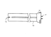
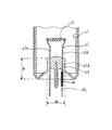
以下本発明の第一実施形態である蛍光ランプを図面を参照して説明する。図1はコンパクト蛍光ランプの概略図、図2は図1の電極封止部端部の断面図を示している。 Hereinafter, a fluorescent lamp according to a first embodiment of the present invention will be described with reference to the drawings. FIG. 1 is a schematic view of a compact fluorescent lamp, and FIG. 2 is a sectional view of an end portion of an electrode sealing portion in FIG.
コンパクト蛍光ランプは、内面に蛍光体層11が形成された外径16〜19mm、内径15〜18mmのガラスバルブの一端を閉塞し、他端部をフレアステム20によって封止した2本のガラスバルブの一端部の閉塞部近傍においてブリッジ12で連結し、所定の水銀およびアルゴンなどの希ガスが封入され、1本の放電路を有する発光管10を形成したものである。また、発光管10の他端側には発光管10の各端部を挿入するための図示しない挿入孔を有する樹脂性の口金30がシリコン接着剤などによって取り付けられている。
The compact fluorescent lamp has two glass bulbs with one end of a glass bulb with an outer diameter of 16 to 19 mm and an inner diameter of 15 to 18 mm with a phosphor layer 11 formed on the inner surface and the other end sealed with a flare stem 20. Are connected by a
そして、上記フレアステム20はニッケルなどからなる一対の導入線21(ウェルズ)が気密に貫通し支持している。これらの導入線21の内端部にはフィラメント電極22を掛け渡して支持することによりフィラメント電極22を構成している。フィラメント22は、タングステンワイヤからなり、2重コイルまたはトリプルコイルで形成されている。フィラメント22は、その両端に形成したレグ部22aを導入線21の一端側で挟持している。フィラメント22には、酸化バリウムなどのような電子放射物質(図示しない)を塗布している。なお、フィラメント22を支持する一対の導入線21は通常、内部リード線21a、ジュメット線21bおよび外部リード線21cにより構成され、ステム20の圧潰封止部においてジュメット線21bが内部リード線21aおよび外部リード線21cにそれぞれ溶接されて接続されている。導入線21の他端部は、発光管10外に導出されており、一対の外部リード線21cには難燃性シリコンチューブ26が被覆され、発光管10の一端側に位置する口金30内部空間内壁に難燃性接着剤により固着されているとともに口金ピン31に接続されている。なお、フレアステム20のジュメット線21bを圧潰封止している圧潰封止部すなわち、ステムチューブ23外径aは4〜14mm、最適には8〜11mmに形成されている。
The flare stem 20 is supported by a pair of lead wires 21 (wells) made of nickel or the like penetrating airtightly. The
フレアステム20は、主に上述したジュメット線21bを圧潰封止するステムチューブ部23および、発光管10端部に溶着されるフレア部24およびフレア部24内方およびフレアチューブ部23内に介在している細管25を備えている。細管25の一端側は、フレアチューブ部23の奥すなわちジュメット線21b圧潰封止部の近傍付近に配置され、細管25一端側を閉塞しないよう溶着され、他端側はフレア部24外方に突出している。そして、細管25他端側の開口を介してバルブ内を排気し、水銀および希ガスなどの放電媒体を封入した後にチップオフされる。なお、発光管10の端部に封着されたフレア部24すなわち、発光管端部からステムチューブ23までの高さbは、20〜40mmに形成されている。
The flare stem 20 is mainly interposed in the
口金30は、口金本体およびこの口金本体の一端面から突設された4本の口金ピン31を有しており、例えばコンパクト形蛍光ランプ用のGY10q形を形成している。
The
口金30全体は、例えば絶縁性を有する合成樹脂で外周面が長手方向断面が略長円形状に形成されているとともに、両端面が略平面状に形成されている。長手方向の一端面には発光管の各端部を挿入する挿入孔が形成されており、接着剤としてのシリコン樹脂によって口金30とバルブとは接着固定されている。
The
このように構成されたコンパクト蛍光ランプは、蛍光ランプの寿命末期には、フィラメント電極22を構成するタングステンやこれに塗布した電子放射物質およびフィラメント22に近い一対の導入線21のニッケルなどの飛散物がステム20表面に付着し、寿命末期時にフィラメント22に塗布した電子放射物質が枯渇し、熱によって電極近傍が異常加熱され、導入線を封止しているステム基体部分が局所加熱され、ステムガラスが溶融する。しかし、ステム20と発光管10内壁の間隔およびステム20と発光管端部距離を所定間隔するよう形成しているので、ステムガラスの溶融が進行したとしても、発光管20を保持する樹脂口金30に到達することなく、溶融をとどめることができる。なお、発光管10を保持している口金30の電極22を封着した発光管端部を挿入する挿入孔の肉厚を厚く形成すれば、寿命末期に電極近傍が高温となりその熱影響を樹脂口金30が受けたとしても、口金30が容易に溶融することを低減することができる。
The compact fluorescent lamp configured in this way is scattered at the end of the life of the fluorescent lamp, such as tungsten constituting the
上記実施形態では、1本の発光管30を屈曲させ連結さした蛍光ランプについて説明したが、2本のガラスバルブをブリッジ連結して形成したものや、3本のガラスバルブを連結して形成した蛍光ランプや4本のガラスバルブを連結して形成した蛍光ランプなど、連結するガラスバルブの数や消費電力に関係なく同様の効果が期待できる。
In the above embodiment, a fluorescent lamp in which one
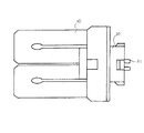
図3は、本発明に係る蛍光ランプの第2の実施形態を示すもので、前述した第1の実施形態の蛍光ランプにおいて、U字形に折曲げた構成した発光管20を2本使用して、これらをブリッジによりW字形に結合して構成したものである。従って、口金30の基本的な構成は、前述した実施例と同様である。図4に示された口金は、例えば絶縁性を有する合成樹脂で外周面が長手方向断面が略長円形状に形成されているとともに、両端面が略平面状に形成されている。長手方向の一端面には発光管10の各端部を挿入する挿入孔が形成されて。
FIG. 3 shows a second embodiment of the fluorescent lamp according to the present invention. In the fluorescent lamp according to the first embodiment described above, two arc tubes 20 configured to be bent in a U shape are used. These are configured by connecting them in a W shape by a bridge. Accordingly, the basic configuration of the
各端部を挿入する挿入孔は、発光管10端部の挿入を可能なように発光管10外径よりわずかに大きい内径で形成され、接着剤としてのシリコン樹脂によって口金30と発光管10とは接着固定されている。また、口金30に形成されている発光管10を挿入する挿入孔のうち、両端に形成された挿入孔は、電極22を封止した発光管10端部が挿入されるため、周囲に渡り肉厚1.5〜2mm程度に形成されている。なお、電極22を封止した発光管端部を挿入する挿入孔に挟まれるように略瓢箪形の中間に位置する2個の発光管端部を挿入可能な挿入孔は肉厚0.8〜1mm程度に形成されている。
The insertion hole for inserting each end is formed with an inner diameter slightly larger than the outer diameter of the
このように、電極22を有する発光管10端部を挿入する挿入孔の肉厚を電極を有さない発光管10端部を挿入する挿入孔よりも肉厚にすることで特に寿命末期に電極近傍が高温となっても樹脂製の口金が変形、溶融することを抑制することができる。
In this way, the thickness of the insertion hole for inserting the end portion of the
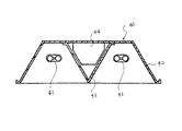
次に、本発明の一実施形態である照明器具を図4を用いて説明する。図4は本発明の照明装置を示す断面概略図である。この照明装置40は、第1の実施形態の蛍光ランプを2灯用いた天井埋め込み灯を示している。図において41は蛍光ランプ、40は照明装置本体である。
Next, the lighting fixture which is one Embodiment of this invention is demonstrated using FIG. FIG. 4 is a schematic cross-sectional view showing the illumination device of the present invention. This
照明装置本体40は、基体42、反射板43および点灯装置44を備えている。基体42は、断面切頭円錐形で、下面周縁に枠縁が形成されている。そして、枠縁を天井の開口に下面から当接した状態で天井に埋設される。反射板43は、断面V字状をなしていて、基体42内を略2分割するように配置されている。点灯装置44は、反射板43の内部に配設されている。そうして、照明装置本体40の内部には、基体42および反射板43により2列の細長い凹窪部が平行に形成されている。なお、図示していないが、凹窪部の長手方向の一端にランプソケットが配設されている。
The illuminating
10…発光管、20…ステム、21…導入線、22…フィラメント電極、
23…ステムチューブ、24…フレア部、25…細管、30…口金
10 ... arc tube, 20 ... stem, 21 ... lead-in wire, 22 ... filament electrode,
23 ... Stem tube, 24 ... Flare, 25 ... Narrow tube, 30 ... Base
Claims (5)
フィラメント電極の両端部を支持する一対のリード線およびこのリード線を封着するステムを有し、前記バルブの少なくとも一端部に封装されたマウントと;
内部空間に連続する前記バルブ端部を挿入する挿入孔が形成されており、電極から導出されたワイヤと電気的に接続される口金ピンを有する口金と;
を具備しており、バルブ内径をa、フレアチューブ外径をbとしたときb/a>0.65以上でありかつバルブ端部から電極側ステム端部までの長さは20mm以上であることを特徴とする蛍光ランプ。 A bulb in which a discharge medium is enclosed and phosphor is applied on the inner surface;
A mount having a pair of lead wires for supporting both ends of the filament electrode and a stem for sealing the lead wires and sealed at least at one end of the bulb;
An insertion hole into which the valve end continuous to the internal space is inserted, and a base having a base pin electrically connected to a wire led out from the electrode;
B / a> 0.65 or more when the valve inner diameter is a and the flare tube outer diameter is b, and the length from the valve end to the electrode stem end is 20 mm or more. Fluorescent lamp characterized by
前記バルブ端部が挿入される挿入孔およびバルブ端部に封止された電極から導出されたワイヤを電気的に接続される口金ピンを有しており、電極を有するバルブ端部を挿入する挿入孔周囲肉厚は、電極を有さないバルブ端部挿入孔周囲肉厚の1.5倍以上の口金と;
を具備していることを特徴とする蛍光ランプ A bulb in which electrodes are sealed at both ends so that a bent discharge path is formed, a discharge medium is sealed inside, and a phosphor is coated on the inner surface;
An insertion hole for inserting a valve end having an electrode, having an insertion hole into which the valve end is inserted and a cap pin for electrically connecting a wire led out from an electrode sealed at the valve end. The thickness around the hole is not less than 1.5 times the thickness around the valve end insertion hole without electrode;
Fluorescent lamp characterized by comprising
この蛍光ランプが装着された器具本体と;
蛍光ランプを点灯する点灯装置と;
を具備していることを特徴とする照明器具。
A fluorescent lamp according to any one of claims 1 to 4;
An instrument body equipped with this fluorescent lamp;
A lighting device for lighting a fluorescent lamp;
The lighting fixture characterized by comprising.
Priority Applications (1)
| Application Number | Priority Date | Filing Date | Title |
|---|---|---|---|
| JP2003431224A JP2005190844A (en) | 2003-12-25 | 2003-12-25 | Fluorescent lamps and lighting fixtures |
Applications Claiming Priority (1)
| Application Number | Priority Date | Filing Date | Title |
|---|---|---|---|
| JP2003431224A JP2005190844A (en) | 2003-12-25 | 2003-12-25 | Fluorescent lamps and lighting fixtures |
Publications (1)
| Publication Number | Publication Date |
|---|---|
| JP2005190844A true JP2005190844A (en) | 2005-07-14 |
Family
ID=34789358
Family Applications (1)
| Application Number | Title | Priority Date | Filing Date |
|---|---|---|---|
| JP2003431224A Pending JP2005190844A (en) | 2003-12-25 | 2003-12-25 | Fluorescent lamps and lighting fixtures |
Country Status (1)
| Country | Link |
|---|---|
| JP (1) | JP2005190844A (en) |
-
2003
- 2003-12-25 JP JP2003431224A patent/JP2005190844A/en active Pending
Similar Documents
| Publication | Publication Date | Title |
|---|---|---|
| JP3599094B2 (en) | Discharge lamps and compact fluorescent lamps | |
| CN100437891C (en) | halogen incandescent lamp | |
| JP3816465B2 (en) | Fluorescent lamp | |
| US10784099B2 (en) | Incandescent light bulb | |
| JP2005190844A (en) | Fluorescent lamps and lighting fixtures | |
| KR100453092B1 (en) | Fluorescent lamp and lighting device | |
| US6211618B1 (en) | Arc discharge lamp with bimetal strip for fast passive lamp failure | |
| JP4624337B2 (en) | Fluorescent lamp | |
| JPH10321192A (en) | Discharge lamps and lighting equipment | |
| JP2008140699A (en) | Fluorescent lamps and lighting fixtures | |
| JP3314462B2 (en) | Fluorescent lamp device | |
| CN101656190A (en) | Fluorescent lamp | |
| JPH10334790A (en) | Discharge lamps and lighting equipment | |
| JP2008181780A (en) | Fluorescent lamps and lighting fixtures | |
| JP2005346976A (en) | Fluorescent lamps and lighting fixtures | |
| JP2004158207A (en) | Fluorescent lamps and lighting equipment | |
| JP2006080015A (en) | Fluorescent lamp device and lighting apparatus | |
| JP3489679B2 (en) | Fluorescent lamp device | |
| JP4888674B2 (en) | Ceramic metal halide lamp with multiple arc tubes | |
| JP2009081047A (en) | Incandescent bulbs and lighting fixtures | |
| JP2005353436A (en) | Low pressure mercury vapor discharge lamp | |
| JP4052045B2 (en) | Fluorescent lamp | |
| JP2004047184A (en) | Light bulb fluorescent lamps and lighting equipment | |
| JP2008204661A (en) | Fluorescent lamps and lighting fixtures | |
| JP2005302385A (en) | Fluorescent lamp |