JP2005190852A - Battery pack - Google Patents
Battery pack Download PDFInfo
- Publication number
- JP2005190852A JP2005190852A JP2003431494A JP2003431494A JP2005190852A JP 2005190852 A JP2005190852 A JP 2005190852A JP 2003431494 A JP2003431494 A JP 2003431494A JP 2003431494 A JP2003431494 A JP 2003431494A JP 2005190852 A JP2005190852 A JP 2005190852A
- Authority
- JP
- Japan
- Prior art keywords
- welding
- rib
- case half
- height
- length
- Prior art date
- Legal status (The legal status is an assumption and is not a legal conclusion. Google has not performed a legal analysis and makes no representation as to the accuracy of the status listed.)
- Granted
Links
- 238000003466 welding Methods 0.000 claims abstract description 166
- 230000033228 biological regulation Effects 0.000 claims description 13
- 230000001105 regulatory effect Effects 0.000 abstract description 51
- 229920005989 resin Polymers 0.000 abstract description 16
- 239000011347 resin Substances 0.000 abstract description 16
- 238000000034 method Methods 0.000 description 8
- 230000007423 decrease Effects 0.000 description 4
- 238000002844 melting Methods 0.000 description 4
- 230000008018 melting Effects 0.000 description 4
- 230000020169 heat generation Effects 0.000 description 3
- 229920003002 synthetic resin Polymers 0.000 description 3
- 239000000057 synthetic resin Substances 0.000 description 3
- 230000001681 protective effect Effects 0.000 description 2
- 230000005856 abnormality Effects 0.000 description 1
- 230000007547 defect Effects 0.000 description 1
- 238000006073 displacement reaction Methods 0.000 description 1
- 230000004927 fusion Effects 0.000 description 1
- 238000009413 insulation Methods 0.000 description 1
- 239000002184 metal Substances 0.000 description 1
- 230000002250 progressing effect Effects 0.000 description 1
- 238000000926 separation method Methods 0.000 description 1
- 229920001169 thermoplastic Polymers 0.000 description 1
- 239000004416 thermosoftening plastic Substances 0.000 description 1
Images


Classifications
-
- Y—GENERAL TAGGING OF NEW TECHNOLOGICAL DEVELOPMENTS; GENERAL TAGGING OF CROSS-SECTIONAL TECHNOLOGIES SPANNING OVER SEVERAL SECTIONS OF THE IPC; TECHNICAL SUBJECTS COVERED BY FORMER USPC CROSS-REFERENCE ART COLLECTIONS [XRACs] AND DIGESTS
- Y02—TECHNOLOGIES OR APPLICATIONS FOR MITIGATION OR ADAPTATION AGAINST CLIMATE CHANGE
- Y02E—REDUCTION OF GREENHOUSE GAS [GHG] EMISSIONS, RELATED TO ENERGY GENERATION, TRANSMISSION OR DISTRIBUTION
- Y02E60/00—Enabling technologies; Technologies with a potential or indirect contribution to GHG emissions mitigation
- Y02E60/10—Energy storage using batteries
Landscapes
- Battery Mounting, Suspending (AREA)
Abstract
【課題】 2つのケース半体を溶着により接合する際の溶融した樹脂がケースの内側又は外側に流出することを防止できる電池パックを提供する。
【解決手段】 上側ケース半体1の外周に形成された側板16の端面15には、切り欠き部12、12…を備えた適長の溶着リブ11、11…が側板16の長さ方向に周設してある。下側ケース半体2の外周に形成された側板23の端面22には、切り欠き部12に対向し、溶着リブ11の長さ方向に平行して、規制リブ21が側板23の内側面に沿って形成されている。規制リブ21の端面22からの高さH2は、溶着リブ11の端面15からの高さH1より低く、規制リブ21の長さL2は、切り欠き部12の長さL1より大きく、規制リブ21の長さ方向の端部夫々の対向部25、25を備えている。
【選択図】 図2PROBLEM TO BE SOLVED: To provide a battery pack capable of preventing a molten resin when two case halves are joined by welding from flowing out to the inside or the outside of the case.
On the end surface 15 of the side plate 16 formed on the outer periphery of the upper case half body 1, suitable length welding ribs 11 having notches 12, 12... Are provided in the length direction of the side plate 16. There is a circumference. The end face 22 of the side plate 23 formed on the outer periphery of the lower case half 2 faces the notch 12 and is parallel to the length direction of the welding rib 11, and the regulating rib 21 is formed on the inner surface of the side plate 23. Are formed along. The height H2 from the end surface 22 of the regulating rib 21 is lower than the height H1 from the end surface 15 of the welding rib 11, and the length L2 of the regulating rib 21 is larger than the length L1 of the notch 12, and the regulating rib 21 Opposite end portions 25, 25 at the ends in the length direction.
[Selection] Figure 2
Description
本発明は、合成樹脂製であって2つのケース半体の外周に形成された側板の端面を溶着により接合して電池を内蔵してある電池パックに関する。 The present invention relates to a battery pack that is made of synthetic resin and has a battery built in by joining end faces of side plates formed on the outer periphery of two case halves by welding.
小型電子機器又は携帯機器などの駆動用電源として、複数個の電池及び配線回路などを内蔵した電池パックが用いられている。電池パックの筐体は、合成樹脂製であって2つのケース半体により構成される。電池パックは、一方のケース半体の凹部を上方向に配置して、該凹部に電池を配置し、他方のケース半体の凹部を下方向にして前記電池を収納し、上側及び下側ケース半体の外周に形成された側板の端面を超音波溶着により溶着して接合し一体化している。 A battery pack incorporating a plurality of batteries, a wiring circuit, and the like is used as a driving power source for small electronic devices or portable devices. The casing of the battery pack is made of synthetic resin and is composed of two case halves. In the battery pack, the concave portion of one case half is disposed upward, the battery is disposed in the concave portion, the concave portion of the other case half is disposed downward, and the battery is stored in the upper and lower cases. The end surfaces of the side plates formed on the outer periphery of the half body are welded and joined together by ultrasonic welding.
近年、機器の軽薄短小化に伴って、該機器に内蔵される電池パックも、小型軽量化が望まれている。これにより電池及び配線回路の小型化のみならず、電池パックの筐体も軽量薄型のものが必要になってきている。 2. Description of the Related Art In recent years, as devices become lighter, thinner, and smaller, battery packs built into the devices are also desired to be reduced in size and weight. As a result, not only miniaturization of the battery and the wiring circuit, but also the battery pack housing is required to be light and thin.
ケース半体の肉厚を薄くすることにより筐体の軽量化が図られているが、前記ケース半体の肉厚を薄く設定する場合、該ケース半体を接合・一体化した際の強度を十分に確保する必要があるとともに、接合位置の精度を保持する必要がある。 The case half is made lighter by reducing the thickness of the case half, but when the case half is set thin, the strength when the case half is joined and integrated is increased. It is necessary to ensure sufficient and to maintain the accuracy of the joining position.
このため、四角形状の上側ケース半体の外周に形成された側板の端面には、四角形状の下側ケース半体の外周に形成された側板の端面と溶着され、複数の切り欠き部を備えた板状の溶着リブを周設し、下側ケース半体の側板の端面には、前記切り欠き部の長さより短く、前記溶着リブの溶着の際の前記端面からの離脱を規制する複数の板状の規制リブが、前記切り欠き部に対向して形成するとともに、規制リブの端面からの高さを、溶着リブの端面からの高さより高くすることにより、超音波溶着時に発生する振動の影響による上側ケース半体の側板の端面と下側ケース半体の側板の端面との位置ずれにより、上側ケース半体の側板の端面に周設された溶着リブが、下側ケース半体の側板の端面から離脱して下側ケース半体の内側に滑り落ちることを防止するものが提案されている(特許文献1参照)。
しかしながら、特許文献1の電池パックにあっては、規制リブの端面からの高さが、溶着リブの端面からの高さより高いため、超音波溶着時の振動により、溶着リブが規制リブ側に移動すると、前記溶着リブが周設された上側ケース半体の内側面と、規制リブの側面が接触する可能性があり、超音波溶着が開始された直後の発熱により、前記上側ケース半体の内側面と、規制リブの側面が溶融する場合があった。このため、溶融した樹脂がケース内部に流れて溶着した場合は、電池又は配線回路などの内蔵部品と干渉し、ケースの側板が変形するなどの外観不良になることがあった。また、ケース内側と電池との間隙は小さいため、ケース内側に流れた溶融樹脂が、内蔵部品からの圧力でケース外部に流れ出て溶着する場合もあり、外観不良などの原因になる虞もあった。
However, in the battery pack of
本発明は、斯かる事情に鑑みてなされたものであり、複数の切り欠き部を備えた前記溶着リブの端面からの高さよりも、前記規制リブの端面からの高さを小さく、前記規制リブの長さは、前記切り欠き部の長さより大きく、前記規制リブの両端夫々は、前記溶着リブと対向する対向部を設けることにより、溶着時に前記溶着リブが周設された一方のケース半体の内側面と、規制リブの側面が接触して溶融することを防止して、溶融した樹脂による不良原因を低減することができ、また、溶着時における振動により、前記溶着リブが、前記規制リブが形成された他方のケース半体の端面から離脱して、該他方のケース半体の内側に滑り落ちることを防止できる電池パックを提供することを目的とする。 The present invention has been made in view of such circumstances, and the height from the end face of the welding rib is smaller than the height from the end face of the welding rib having a plurality of notches, and the restriction rib is provided. Is longer than the length of the cut-out portion, and both ends of the regulating rib are provided with opposing portions facing the welding rib, so that one case half in which the welding rib is circumferentially provided at the time of welding is provided. It is possible to reduce the cause of defects caused by the molten resin by preventing the inner side surface of the metal plate and the side surface of the regulating rib from contacting and melting, and the welding rib is caused to vibrate by vibration during welding. It is an object of the present invention to provide a battery pack that can be prevented from slipping off from the end face of the other case half formed with the inside of the other case half.
また、本発明の他の目的は、前記規制リブの端面からの高さを前記溶着リブの端面からの高さの80%以下にすることにより、溶着時に前記溶着リブが周設されたケース半体の内側面と、規制リブの側面が接触して溶融することを防止することができる電池パックを提供することにある。 Another object of the present invention is to reduce the height from the end face of the regulation rib to 80% or less of the height from the end face of the weld rib, thereby making the case half in which the weld rib is provided circumferentially at the time of welding. An object of the present invention is to provide a battery pack capable of preventing the inner side surface of the body and the side surface of the regulating rib from contacting and melting.
また、本発明の他の目的は、前記規制リブの対向部の長さが、前記溶着リブの高さの150%以上500%以下にすることにより、溶着時における振動により、前記溶着リブが、前記他方のケース半体の内側に滑り落ちることを防止しつつ、溶着時に前記溶着リブが周設されたケース半体の内側面と、規制リブの側面が接触して溶融する可能性を低減し、溶着時の溶融した樹脂がケース外側又は内側に流出することを防止することができる電池パックを提供することにある。 Another object of the present invention is that the length of the opposing portion of the regulating rib is 150% or more and 500% or less of the height of the welding rib, so that the welding rib is caused by vibration during welding, While preventing sliding down to the inside of the other case half, reducing the possibility that the inner side surface of the case half around which the welding rib is provided at the time of welding and the side surface of the regulating rib are in contact with each other and melted, An object of the present invention is to provide a battery pack capable of preventing molten resin at the time of welding from flowing out of the case outside or inside.
また、本発明の他の目的は、前記規制リブの対向部の長さが、前記溶着リブの高さの200%以上400%以下にすることにより、溶着時における振動により、前記溶着リブが、前記他方のケース半体の内側に滑り落ちることを確実に防止しつつ、溶着時に前記溶着リブが周設されたケース半体の内側面と、規制リブの側面が接触する面積をさらに小さくして溶融する可能性をさらに低減し、溶着時の溶融した樹脂がケース外側又は内側に流出することを確実に防止することができる電池パックを提供することにある。 Another object of the present invention is that the length of the facing portion of the regulation rib is 200% or more and 400% or less of the height of the welding rib, so that the welding rib is caused by vibration during welding, While preventing the inside of the other half of the case from slipping down, the area of contact between the inner side surface of the case half around which the welding rib is provided and the side surface of the regulating rib during melting is further reduced. It is an object of the present invention to provide a battery pack that can further reduce the possibility of occurrence and reliably prevent the molten resin at the time of welding from flowing out to the outside or inside of the case.
第1発明に係る電池パックは、外周に側板が形成された2つのケース半体を溶着により接合して構成されるケースと、該ケースに収納される電池を備え、一方のケース半体の側板の端面には、他方のケース半体と溶着され、複数の切り欠き部を備えた溶着リブが周設され、前記他方のケース半体の側板の端面には、前記溶着リブの前記端面からの溶着における離脱を規制する複数の規制リブが、前記切り欠き部に対向して形成された電池パックにおいて、前記規制リブの端面からの高さは、前記溶着リブの端面からの高さより低く、前記規制リブの長さは、前記切り欠き部の長さより長く、前記規制リブの両端部夫々は、前記溶着リブと対向する対向部を備えることを特徴とする。 A battery pack according to a first aspect of the present invention includes a case configured by welding two case halves having side plates formed on the outer periphery thereof, and a battery stored in the case, and the side plate of one case half The end face of the other case half is welded to the other case half and is provided with a plurality of cutout ribs. The end face of the side plate of the other case half is connected to the end face of the weld rib from the end face. In the battery pack in which a plurality of regulating ribs that regulate detachment in welding are formed facing the notch, the height from the end surface of the regulating rib is lower than the height from the end surface of the welding rib, The length of the regulation rib is longer than the length of the notch, and both end portions of the regulation rib each have a facing portion that faces the welding rib.
第2発明に係る電池パックは、前記規制リブの端面からの高さは、前記溶着リブの端面からの高さの80%以下であることを特徴とする。 The battery pack according to a second aspect of the present invention is characterized in that a height from the end face of the regulation rib is 80% or less of a height from the end face of the welding rib.
第3発明に係る電池パックは、前記対向部の前記規制リブの長さは、前記溶着リブの端面からの高さの150%以上500%以下であることを特徴とする。 The battery pack according to a third aspect of the invention is characterized in that the length of the regulating rib of the facing portion is 150% or more and 500% or less of the height from the end face of the welding rib.
第4発明に係る電池パックは、前記対向部の前記規制リブの長さは、前記溶着リブの端面からの高さの200%以上400%以下であることを特徴とする。 The battery pack according to a fourth aspect of the invention is characterized in that the length of the regulating rib of the facing portion is 200% or more and 400% or less of the height from the end face of the welding rib.
第1の発明にあっては、前記規制リブが形成された端面を上向きにして前記他方のケース半体を配置し、電池又は配線回路などの内蔵部品を該ケース半体に収納した後に、前記溶着リブが形成された端面を下向きして、前記溶着リブが前記他方のケース半体の端面に当接するように前記一方のケース半体を配置し、超音波溶着用治具を前記一方のケース半体上側に当接させる。溶着時は、高周波を印加して前記溶着リブと前記他方のケース半体の端面との摩擦熱により前記溶着リブと前記端面とを溶融して溶着が行われる。溶着時に上側に配置された一方のケース半体に周設された前記溶着リブの端面からの高さより、溶着時に下側に配置された他方のケース半体に形成された前記規制リブの端面からの高さが低いため、溶着開始後の振動により、前記溶着リブが前記他方のケース半体の端面の内側方向に位置がずれた場合でも、前記溶着リブが周設された一方のケース半体の内側面と、前記規制リブの側面とが接触する可能性がない。このため、溶着開始時の発熱により、前記一方のケース半体の内側面と規制リブの側面とが溶融して、溶融した樹脂がケース内側の前記内蔵部品に混入し、また、ケース外側へ流出することを防止できる。また、前記規制リブの長さは、前記切り欠き部の長さより長く、前記規制リブの両端部夫々に、前記溶着リブと対向する対向部を設けることにより、溶着時の振動により前記溶着リブが前記他方のケース半体の端面の内側方向に位置がずれた場合でも、前記規制リブの両端部夫々の対向部により、前記溶着リブの前記端面からの離脱が規制され、前記溶着リブが前記他方のケース半体の内側へ落下することが防止できる。 In the first invention, the other case half is disposed with the end face on which the regulation rib is formed facing upward, and a built-in component such as a battery or a wiring circuit is accommodated in the case half, The one case half is disposed so that the end surface on which the welding rib is formed faces downward, and the welding rib contacts the end surface of the other case half, and the ultrasonic welding jig is placed on the one case. Abut on the upper half. At the time of welding, welding is performed by applying a high frequency to melt the welding rib and the end face by frictional heat between the welding rib and the end face of the other case half. From the height from the end surface of the welding rib provided around one case half disposed on the upper side during welding, from the end surface of the regulation rib formed on the other case half disposed below during welding. Therefore, even if the position of the welding rib is shifted inwardly of the end surface of the other case half due to vibration after the start of welding, one case half in which the welding rib is provided circumferentially is provided. There is no possibility of contact between the inner side surface and the side surface of the regulating rib. For this reason, due to the heat generated at the start of welding, the inner side surface of the one case half and the side surface of the regulating rib are melted, and the molten resin is mixed into the built-in parts inside the case and flows out to the outside of the case. Can be prevented. Further, the length of the regulation rib is longer than the length of the notch, and by providing opposing portions facing the welding rib at both ends of the regulation rib, the welding rib is caused by vibration during welding. Even when the position is displaced inwardly of the end surface of the other case half, the opposing portions of both ends of the restriction rib restrict the detachment of the welding rib from the end surface, and the welding rib is in the other side. Can be prevented from falling inside the case half.
第2の発明にあっては、前記規制リブの端面からの高さを、前記溶着リブの端面からの高さの80%以下にすることにより、溶着が開始される際の前記溶着リブが周設された一方のケース半体の内側面と、規制リブの側面とが接触することを確実に防止することができる。すなわち、前記規制リブが形成されているため、溶着開始時の振動により、前記溶着リブの溶着面が他方のケース半体の端面の内側方向に位置ずれをして該ケース半体の内側に落下した状態で溶着することを防止できる。一方、前記規制リブの高さが、前記溶着リブの高さの80%を越える場合は、溶着が開始後の発熱により、前記溶着リブと前記他方のケース半体の端面とが溶融していく過程において、前記溶着リブが周設されたケース半体の内側面と、規制リブの側面とが接触して溶着する可能性がある。 In the second invention, the height from the end face of the restriction rib is set to 80% or less of the height from the end face of the weld rib, so that the weld rib at the start of welding is surrounded. It can prevent reliably that the inner surface of one case half provided and the side surface of a control rib contact. That is, since the restriction rib is formed, the welding surface of the welding rib is displaced inwardly of the end surface of the other case half due to vibration at the start of welding and falls to the inside of the case half. It is possible to prevent welding in a state of being damaged. On the other hand, when the height of the regulating rib exceeds 80% of the height of the welding rib, the welding rib and the end face of the other case half are melted due to heat generation after the welding starts. In the process, there is a possibility that the inner side surface of the case half around which the welding rib is provided and the side surface of the regulating rib come into contact with each other and weld.
第3の発明にあっては、前記規制リブの前記対向部の長さを、前記溶着リブの高さの150%以上500%以下にすることにより、溶着開始後の振動により、前記溶着リブの溶着面が他方のケース半体の端面の内側方向に位置ずれをして該ケース半体の内側に落下した状態で溶着することを防止することができるとともに、溶着開始後の発熱により、前記溶着リブが周設されたケース半体の内側面と、規制リブの側面とが接触して溶着する可能性を低減することができる。すなわち、前記対向部の長さが前記溶着リブの高さの150%未満である場合は、溶着開始後に溶着が進行する過程において、前記溶着リブが規制リブの端部から外れて、前記他方のケース半体の内側に落下した状態で溶着される可能性がある。一方、前記対向部の長さが前記溶着リブの高さの500%を超える場合は、前記規制リブの対向部の面積が大きいため、溶着開始に溶着が進行する過程において、前記溶着リブの側面と前記規制リブの側面とが接触して溶着する可能性がある。 In the third invention, the length of the facing portion of the regulating rib is set to 150% or more and 500% or less of the height of the welding rib, so that vibration of the welding rib is caused by vibration after starting welding. It is possible to prevent the welding surface from being displaced in the inner side direction of the end surface of the other case half and falling to the inside of the case half and to prevent the welding due to the heat generated after the welding starts. It is possible to reduce the possibility that the inner side surface of the case half provided with the ribs and the side surface of the regulating rib come into contact with each other and weld. That is, when the length of the facing portion is less than 150% of the height of the welding rib, the welding rib is detached from the end of the regulating rib in the process of welding after the start of welding. There is a possibility of welding while falling inside the case half. On the other hand, when the length of the facing portion exceeds 500% of the height of the welding rib, since the area of the facing portion of the regulating rib is large, the side surface of the welding rib in the process of welding progressing at the start of welding. And the side surface of the regulating rib may come into contact and weld.
第4の発明にあっては、前記規制リブの前記対向部の長さを、前記溶着リブの高さの200%以上400%以下にすることにより、溶着開始後の振動により、前記溶着リブの溶着面が他方のケースの端面の内側方向に位置ずれをして該ケース半体の内側に落下した状態で溶着することを防止することができるとともに、溶着開始後の発熱により、前記溶着リブが周設されたケース半体の内側面と規制リブの側面とが接触して溶着する可能性を低減することができる。すなわち、前記対向部の長さの下限値を前記溶着リブの高さの150%から200%にすることにより、溶着開始後に溶着が進行する過程において、前記溶着リブが規制リブの端部から外れて、前記他方のケース半体の内側に落下した状態で溶着される可能性を少なくできる。一方、前記対向部の長さの上限値を前記溶着リブの高さの500%から400%にすることにより、前記規制リブの対向部の面積をより小さくすることができ、溶着開始に溶着が進行する過程において、前記溶着リブの側面と前記規制リブの側面とが接触して溶着する可能性を少なくすることができる。 In 4th invention, the length of the said opposing part of the said regulation rib shall be 200% or more and 400% or less of the height of the said welding rib, By the vibration after a welding start, the said welding rib's It is possible to prevent the welding surface from being displaced in the inner side direction of the end surface of the other case and falling to the inside of the case half body, and to prevent the welding rib from being generated by heat generation after the welding starts. The possibility that the inner side surface of the circumferential case half and the side surface of the regulating rib come into contact with each other to be welded can be reduced. That is, by setting the lower limit value of the length of the facing portion to 150% to 200% of the height of the welding rib, the welding rib is detached from the end portion of the regulating rib in the process of welding progress after the welding starts. Thus, it is possible to reduce the possibility of being welded in the state of falling inside the other case half. On the other hand, by setting the upper limit value of the length of the facing portion to 500% to 400% of the height of the welding rib, the area of the facing portion of the regulating rib can be further reduced, and welding is started at the start of welding. In the process of proceeding, the possibility that the side surface of the welding rib and the side surface of the regulating rib come into contact with each other and weld can be reduced.
本発明にあっては、前記規制リブの端面からの高さが、前記溶着リブの端面からの高さより低く、前記切り欠き部に対向して形成された前記規制リブの長さは、前記切り欠き部の長さより長く、前記規制リブの両端部夫々に、前記溶着リブと対向する対向部を設けることにより、溶着の開始時における振動により前記溶着リブがケース半体の内側に滑り落ちることを防止できるとともに、溶着の開始後に前記溶着リブが周設されたケース半体の内側面に、規制リブの側面が接触することを防止でき、溶着時における溶融樹脂が、ケース外側又は内側に流出することが防止でき、溶融した樹脂による不良原因を除去することができる。 In the present invention, the height from the end face of the restriction rib is lower than the height from the end face of the welding rib, and the length of the restriction rib formed to face the notch is the cut edge. Longer than the length of the notch, and by providing opposing portions facing the welding ribs at both ends of the regulating rib, the welding ribs are prevented from sliding down inside the case half due to vibration at the start of welding. In addition, it is possible to prevent the side surface of the regulating rib from coming into contact with the inner side surface of the case half around which the welding rib is provided after the start of welding, and the molten resin at the time of welding flows out to the outside or inside of the case Can be prevented, and the cause of failure due to the molten resin can be removed.
また、本発明にあっては、溶着が開始される際の前記溶着リブが周設されたケース半体の内側面と、規制リブの側面が接触することを確実に防止することができる。 Moreover, in this invention, it can prevent reliably that the inner side surface of the case half body in which the said welding rib was provided in the circumference | surroundings at the time of a welding start, and the side surface of a control rib contact.
また、本発明にあっては、溶着開始後に溶着リブがケース内側に滑り落ちることを防止することができるとともに、溶着の過程における溶融した樹脂がケースの外側又は内側に流出することを防止することができる。 Further, in the present invention, it is possible to prevent the welding rib from sliding down to the inside of the case after the start of welding, and to prevent the molten resin in the welding process from flowing out to the outside or inside of the case. it can.
また、本発明にあっては、溶着開始後に溶着リブがケース内側に滑り落ちることを確実に防止することができるとともに、溶着の過程における溶融した樹脂がケースの外側又は内側に流出することを防止することができる。 Further, in the present invention, it is possible to reliably prevent the welding rib from slipping down to the inside of the case after the start of welding, and to prevent molten resin in the welding process from flowing out to the outside or inside of the case. be able to.
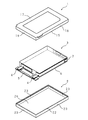
図1は溶着前の電池パックの構造を示す分解斜視図である。図において、1及び2夫々は熱可塑性の合成樹脂製の上側ケース半体及び下側ケース半体であり、溶着により接合してケース本体となる。上側ケース半体1及び下側ケース半体2夫々は、略四角形の平板17、26の周辺に側板16、23が周設されている。
FIG. 1 is an exploded perspective view showing the structure of the battery pack before welding. In the figure,
溶着時には、下側ケース半体2の側板23を上方向にして、下側ケース半体2を配置し、下側ケース半体2の側板23で囲まれた凹部には、電力を取り出すための正負の電極板4、4、過充電及び過放電を防止する回路を構成し、正負の電極板4、4と接続する保護回路基板5、電極板4と電池3の筐体とを絶縁する絶縁板6、短絡等の異常時に電池3を保護する保護素子7などが取り付けられた電池3を収納した後に、上側ケース半体1の側板16を下側にして、下側ケース半体2の側板23と上側ケース半体1の側板16とを当接し、上側ケース半体1の上側に超音波溶着用治具を当接して超音波溶着を行い、上側ケース半体1と下側ケース半体2とが溶着して一体化される。
When welding, the
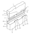
図2は上側ケース半体1と下側ケース半体2との溶着前の接合部分を示す斜視図である。図3は上側ケース半体1及び下側ケース半体2のケース内側から見た溶着前の接合部分を示す拡大図である。上側ケース半体1の側板16の端側外周は、厚さ方向の断面がL字状の嵌合部17が周設され、下側ケース半体2の側板23の外側面に周設された鍔縁24に嵌合される。これにより、溶着の際に上側ケース半体1の側板16が下側ケース2の側板23の外側に外れることを防止して、側板16及び側板23の位置合わせを行う。
FIG. 2 is a perspective view showing a joint portion between the
側板16の端面15には、切り欠き部12、12…を備えた適長の溶着リブ11、11…が側板16の長さ方向に周設してある。溶着リブ11の厚さは、側板16側から溶着リブ11の溶着面の方向にテーパ状に形成されてあり、前記厚さ寸法は溶着リブ11の前記溶着面で小さくなしてある。
On the
側板23の端面22には、切り欠き部12に対向し、溶着リブ11の長さ方向に平行して、規制リブ21が側板23の内側面に沿って形成されている。溶着の際には、端面22に溶着リブ11の前記溶着面が当接される。
On the
規制リブ21の端面22からの高さH2は、溶着リブ11の端面15からの高さH1の80%以下の寸法であり、規制リブ21の長さL2は、切り欠き部12の長さL1より大きく、規制リブ21の長さ方向の端部夫々は、溶着リブ11と対向する対向部25、25を備え、対向部25、25の長さDは、溶着リブ11の高さH1の150%以上500%以下の寸法である。
The height H2 from the
例えば、溶着リブ11の長さは4mm、切り欠き部12の長さL1は4mm、溶着リブ11の高さH1は0.35mmを用いることができる。この場合は、規制リブ21の対向部25の長さは0.525mm以上1.75mm以下の寸法である。
For example, the length of the
また、より好ましくは、規制リブ21の対向部25、25の長さDは、溶着リブ11の高さH1の200%以上400%以下の寸法である。この場合は、規制リブ21の対向部25の長さは0.7mm以上1.4mm以下の寸法である。より好ましくは、規制リブ21の対向部25の長さは1.0mmである。これにより、対向部25の面積をより小さくすることにより、溶着リブ11と規制リブ21との溶融の可能性を少なくすることができる。
More preferably, the length D of the facing
次に超音波溶着時の動作について説明する。図4は上側ケース半体1と下側ケース半体2との溶着後の接合部分を示す斜視図である。下側ケース半体2の側板23で囲まれた凹部に回路部品が取り付けられた電池3を配置し、上側ケース半体1の溶着リブ11を下側ケース半体2の端面22に当接して配置する。
Next, the operation at the time of ultrasonic welding will be described. FIG. 4 is a perspective view showing a joint portion after the
超音波溶着用の治具を上側ケース半体1の上側に当接して所定の位置に配置し、所要の高周波を印加すると、上側ケース半体1に振動が加えられ、溶着リブ11と下側ケース半体2の端面22とが振動による摩擦熱により高温に加熱され、溶着リブ11と下側ケース半体2の端面22とは溶融する。前記高周波の印加を終了すると、溶融した部分の温度は徐々に低下し、溶融する樹脂の量が減少し、上側ケース半体1の端面15と下側ケース半体2の端面22が溶着して一体化される。
When an ultrasonic welding jig is placed at a predetermined position in contact with the upper side of the
溶着の過程において、前記摩擦熱により溶着リブ11、溶着リブ11の近傍の側板13、端面22、規制リブ21などが加熱される。しかし、溶着開始時の最も高温に加熱された状態において、規制リブ21の端面22からの高さが溶着リブ11の端面15からの高さよりも低いため、側板13の内側面と規制リブ21の外側面が接触することがなく、側板13の内側面と規制リブ21の外側面とが溶融して、溶融した樹脂が上側及び下側ケース半体1、2の内側に流入して電池3などの内蔵部品に混入することを防止でき、また、電池3と上側及び下側ケース半体1、2との間隙は小さいため、電池3との間隙に流入した溶融樹脂が、間隙から流出して、上側及び下側ケース半体1、2の外側へ流出することを防止できる。
During the welding process, the
また、前記高周波の印加を終了すると、摩擦熱が徐々に低下し、溶融する樹脂の量も減少することから、規制リブ21の高さは小さい方が好ましい。同様に、規制リブ21の端部夫々の対向部25、25の面積は小さい方が、溶着リブ11と規制リブ21との溶融の可能性を少なくすることができ、不要な溶融樹脂の流出を抑えることが可能になる。
Further, when the application of the high frequency is finished, the frictional heat gradually decreases and the amount of resin to be melted also decreases. Therefore, it is preferable that the height of the regulating
溶着リブ11の肉厚はテーパ状に形成されていたが、この形状に限られるものではない。例えば、三角形状、矩形など、溶着強度を確保できるものであれば、いずれの形状も可能である。
Although the thickness of the
溶着リブ11の高さは0.35mmに限られるものではなく、0.4mm、上側及び下側ケース半体1、2の大きさに応じて、適切な寸法に形成することが可能である。また、溶着リブ11の長さも4mmに限られるものではなく、5mm、6mmと適切な寸法に形成することが可能である。
The height of the
規制リブ21の長さ方向の縦断面形状は四角形状に限られるものではなく、三角形状、半円弧状などの形状であってもよい。
The longitudinal cross-sectional shape of the regulating
1 上側ケース半体
2 下側ケース半体
3 電池
11 溶着リブ
12 切り欠き部
13 側板
15 端面
16 側板
21 規制リブ
22 端面
23 側板
25 対向部
DESCRIPTION OF
Claims (4)
前記規制リブの端面からの高さは、前記溶着リブの端面からの高さより低く、前記規制リブの長さは、前記切り欠き部の長さより長く、前記規制リブの両端部夫々は、前記溶着リブと対向する対向部を備えることを特徴とする電池パック。 A case formed by welding two case halves each having a side plate formed on the outer periphery thereof by welding, and a battery housed in the case; A plurality of notches that are welded to the body and provided with a plurality of notches, and that are provided on the end face of the side plate of the other case half to restrict detachment of the weld rib from the end face. In the battery pack in which the rib is formed to face the notch,
The height from the end face of the restriction rib is lower than the height from the end face of the welding rib, the length of the restriction rib is longer than the length of the notch, and both end portions of the restriction rib are welded. A battery pack comprising a facing portion facing the rib.
Priority Applications (1)
| Application Number | Priority Date | Filing Date | Title |
|---|---|---|---|
| JP2003431494A JP4282470B2 (en) | 2003-12-25 | 2003-12-25 | Battery pack |
Applications Claiming Priority (1)
| Application Number | Priority Date | Filing Date | Title |
|---|---|---|---|
| JP2003431494A JP4282470B2 (en) | 2003-12-25 | 2003-12-25 | Battery pack |
Publications (2)
| Publication Number | Publication Date |
|---|---|
| JP2005190852A true JP2005190852A (en) | 2005-07-14 |
| JP4282470B2 JP4282470B2 (en) | 2009-06-24 |
Family
ID=34789496
Family Applications (1)
| Application Number | Title | Priority Date | Filing Date |
|---|---|---|---|
| JP2003431494A Expired - Fee Related JP4282470B2 (en) | 2003-12-25 | 2003-12-25 | Battery pack |
Country Status (1)
| Country | Link |
|---|---|
| JP (1) | JP4282470B2 (en) |
Cited By (7)
| Publication number | Priority date | Publication date | Assignee | Title |
|---|---|---|---|---|
| EP2068382A2 (en) | 2007-12-03 | 2009-06-10 | Byd Company Limited | Battery cover |
| US7719233B2 (en) | 2006-05-31 | 2010-05-18 | Sanyo Electric Co., Ltd. | Battery pack |
| JP2010262757A (en) * | 2009-04-30 | 2010-11-18 | Sanyo Electric Co Ltd | Battery pack |
| US7935441B2 (en) | 2006-03-03 | 2011-05-03 | Sanyo Electric Co., Ltd. | Battery pack |
| CN104852011A (en) * | 2014-02-18 | 2015-08-19 | 日立麦克赛尔株式会社 | Non-aqueous electrolyte secondary battery |
| EP4274013A1 (en) | 2021-02-25 | 2023-11-08 | LG Energy Solution, Ltd. | Waterproof battery pack case for preventing over-fusion |
| KR102958747B1 (en) * | 2021-02-25 | 2026-04-28 | 주식회사 엘지에너지솔루션 | A waterproof battery pack case preventing over-welding |
Citations (3)
| Publication number | Priority date | Publication date | Assignee | Title |
|---|---|---|---|---|
| JP2001256939A (en) * | 2000-03-14 | 2001-09-21 | Matsushita Electric Ind Co Ltd | Battery pack |
| JP2001256938A (en) * | 2000-03-14 | 2001-09-21 | Matsushita Electric Ind Co Ltd | Battery pack |
| JP2002245993A (en) * | 2001-02-21 | 2002-08-30 | Matsushita Electric Ind Co Ltd | Battery pack |
-
2003
- 2003-12-25 JP JP2003431494A patent/JP4282470B2/en not_active Expired - Fee Related
Patent Citations (3)
| Publication number | Priority date | Publication date | Assignee | Title |
|---|---|---|---|---|
| JP2001256939A (en) * | 2000-03-14 | 2001-09-21 | Matsushita Electric Ind Co Ltd | Battery pack |
| JP2001256938A (en) * | 2000-03-14 | 2001-09-21 | Matsushita Electric Ind Co Ltd | Battery pack |
| JP2002245993A (en) * | 2001-02-21 | 2002-08-30 | Matsushita Electric Ind Co Ltd | Battery pack |
Cited By (9)
| Publication number | Priority date | Publication date | Assignee | Title |
|---|---|---|---|---|
| US7935441B2 (en) | 2006-03-03 | 2011-05-03 | Sanyo Electric Co., Ltd. | Battery pack |
| US7719233B2 (en) | 2006-05-31 | 2010-05-18 | Sanyo Electric Co., Ltd. | Battery pack |
| EP2068382A2 (en) | 2007-12-03 | 2009-06-10 | Byd Company Limited | Battery cover |
| EP2068382A3 (en) * | 2007-12-03 | 2010-02-24 | Byd Company Limited | Battery cover |
| JP2010262757A (en) * | 2009-04-30 | 2010-11-18 | Sanyo Electric Co Ltd | Battery pack |
| CN104852011A (en) * | 2014-02-18 | 2015-08-19 | 日立麦克赛尔株式会社 | Non-aqueous electrolyte secondary battery |
| EP4274013A1 (en) | 2021-02-25 | 2023-11-08 | LG Energy Solution, Ltd. | Waterproof battery pack case for preventing over-fusion |
| EP4274013A4 (en) * | 2021-02-25 | 2024-09-11 | LG Energy Solution, Ltd. | WATERPROOF BATTERY PACK ENCLOSURE TO PREVENT OVERFUSION |
| KR102958747B1 (en) * | 2021-02-25 | 2026-04-28 | 주식회사 엘지에너지솔루션 | A waterproof battery pack case preventing over-welding |
Also Published As
| Publication number | Publication date |
|---|---|
| JP4282470B2 (en) | 2009-06-24 |
Similar Documents
| Publication | Publication Date | Title |
|---|---|---|
| JP4972823B2 (en) | Battery pack | |
| US7622219B2 (en) | Battery pack | |
| JP5034135B2 (en) | Battery and manufacturing method thereof | |
| JP4588331B2 (en) | Square battery and manufacturing method thereof | |
| EP1487033A1 (en) | Battery and method of manufacturing the battery | |
| EP2068382B1 (en) | Battery cover | |
| CN106415882A (en) | Battery pack and method of assembling the battery pack | |
| KR20090075396A (en) | Battery pack | |
| EP4071900A1 (en) | Battery pack | |
| US20130115492A1 (en) | Sealed type battery | |
| JP4282470B2 (en) | Battery pack | |
| CN113767445A (en) | High voltage fuse with anti-ring breakaway structure | |
| JP2012209174A (en) | Battery back and joining method of separation cases | |
| JP6275275B2 (en) | Coupling method, combined body, stator of rotating electric machine, and method of manufacturing stator of rotating electric machine | |
| JP3806527B2 (en) | Electrical device case and method of manufacturing the same | |
| JP3507397B2 (en) | Battery pack | |
| EP1829135B1 (en) | Battery case | |
| JP2011076968A (en) | Battery housing case and its joining method | |
| JP4837294B2 (en) | Battery pack | |
| JP6447266B2 (en) | Manufacturing method of current interrupting device | |
| US20230076491A1 (en) | Battery pack and electronic device | |
| JP7830495B2 (en) | Battery and method for manufacturing a battery | |
| JP2008027616A (en) | Battery pack and manufacturing method of battery pack | |
| JP7508172B2 (en) | Battery pack case with structure to prevent over-welding | |
| JP3754792B2 (en) | Temperature fuse and temperature fuse mounting structure for secondary battery |
Legal Events
| Date | Code | Title | Description |
|---|---|---|---|
| A621 | Written request for application examination |
Free format text: JAPANESE INTERMEDIATE CODE: A621 Effective date: 20050720 |
|
| A977 | Report on retrieval |
Free format text: JAPANESE INTERMEDIATE CODE: A971007 Effective date: 20081010 |
|
| A131 | Notification of reasons for refusal |
Free format text: JAPANESE INTERMEDIATE CODE: A131 Effective date: 20081028 |
|
| A521 | Request for written amendment filed |
Free format text: JAPANESE INTERMEDIATE CODE: A523 Effective date: 20081216 |
|
| TRDD | Decision of grant or rejection written | ||
| A01 | Written decision to grant a patent or to grant a registration (utility model) |
Free format text: JAPANESE INTERMEDIATE CODE: A01 Effective date: 20090217 |
|
| A01 | Written decision to grant a patent or to grant a registration (utility model) |
Free format text: JAPANESE INTERMEDIATE CODE: A01 |
|
| A61 | First payment of annual fees (during grant procedure) |
Free format text: JAPANESE INTERMEDIATE CODE: A61 Effective date: 20090317 |
|
| R151 | Written notification of patent or utility model registration |
Ref document number: 4282470 Country of ref document: JP Free format text: JAPANESE INTERMEDIATE CODE: R151 |
|
| FPAY | Renewal fee payment (event date is renewal date of database) |
Free format text: PAYMENT UNTIL: 20120327 Year of fee payment: 3 |
|
| FPAY | Renewal fee payment (event date is renewal date of database) |
Free format text: PAYMENT UNTIL: 20120327 Year of fee payment: 3 |
|
| S111 | Request for change of ownership or part of ownership |
Free format text: JAPANESE INTERMEDIATE CODE: R313117 |
|
| FPAY | Renewal fee payment (event date is renewal date of database) |
Free format text: PAYMENT UNTIL: 20120327 Year of fee payment: 3 |
|
| R350 | Written notification of registration of transfer |
Free format text: JAPANESE INTERMEDIATE CODE: R350 |
|
| FPAY | Renewal fee payment (event date is renewal date of database) |
Free format text: PAYMENT UNTIL: 20120327 Year of fee payment: 3 |
|
| FPAY | Renewal fee payment (event date is renewal date of database) |
Free format text: PAYMENT UNTIL: 20130327 Year of fee payment: 4 |
|
| R250 | Receipt of annual fees |
Free format text: JAPANESE INTERMEDIATE CODE: R250 |
|
| FPAY | Renewal fee payment (event date is renewal date of database) |
Free format text: PAYMENT UNTIL: 20130327 Year of fee payment: 4 |
|
| FPAY | Renewal fee payment (event date is renewal date of database) |
Free format text: PAYMENT UNTIL: 20140327 Year of fee payment: 5 |
|
| R250 | Receipt of annual fees |
Free format text: JAPANESE INTERMEDIATE CODE: R250 |
|
| R250 | Receipt of annual fees |
Free format text: JAPANESE INTERMEDIATE CODE: R250 |
|
| S111 | Request for change of ownership or part of ownership |
Free format text: JAPANESE INTERMEDIATE CODE: R313117 |
|
| R350 | Written notification of registration of transfer |
Free format text: JAPANESE INTERMEDIATE CODE: R350 |
|
| LAPS | Cancellation because of no payment of annual fees |