JP2005201323A - Pulsation reducing device or pulsation reducing hydraulic device - Google Patents
Pulsation reducing device or pulsation reducing hydraulic device Download PDFInfo
- Publication number
- JP2005201323A JP2005201323A JP2004006863A JP2004006863A JP2005201323A JP 2005201323 A JP2005201323 A JP 2005201323A JP 2004006863 A JP2004006863 A JP 2004006863A JP 2004006863 A JP2004006863 A JP 2004006863A JP 2005201323 A JP2005201323 A JP 2005201323A
- Authority
- JP
- Japan
- Prior art keywords
- cylinder
- pressure
- pipe
- discharge pipe
- hydraulic
- Prior art date
- Legal status (The legal status is an assumption and is not a legal conclusion. Google has not performed a legal analysis and makes no representation as to the accuracy of the status listed.)
- Withdrawn
Links
Images


Landscapes
- Fluid-Pressure Circuits (AREA)
- Forklifts And Lifting Vehicles (AREA)
- Pipe Accessories (AREA)
- Supply Devices, Intensifiers, Converters, And Telemotors (AREA)
Abstract
Description
本発明は、例えば油圧式フォークリフト、油圧式ウインチ、油圧クレーン、油圧シリンダー等の流体(油圧、水圧、空気圧等)管路において、管路内に流れる加圧流体による脈動、騒音を低減するために用いられる脈動低減装置、又は脈動低減油圧装置に関する。 The present invention is to reduce pulsation and noise caused by pressurized fluid flowing in a pipe such as a hydraulic forklift, a hydraulic winch, a hydraulic crane, a hydraulic cylinder, etc. The present invention relates to a pulsation reducing device or a pulsation reducing hydraulic device used.
一般に、油圧式フォークリフト、油圧式ウインチ、油圧クレーン等の建設機械、船舶の甲板機械等は、走行用、作業用、駆動用のアクチュエータ(油圧モータ、油圧シリンダ等)は、配管、弁類を介して、油圧ポンプから供給された高圧作動油により駆動される。 In general, construction machinery such as hydraulic forklifts, hydraulic winches, hydraulic cranes, ship deck machinery, etc., travel, work, and drive actuators (hydraulic motors, hydraulic cylinders, etc.) are connected via piping and valves. And driven by high-pressure hydraulic oil supplied from a hydraulic pump.
このような装置においては、油圧ポンプから吐出する高圧の作動油は脈動を生じるため、油圧ポンプとアクチュエータとの配管、特に油圧ポンプの吐出ポートに接続された吐出管路は、その内部を流通する作動油の脈動に伴って振動する。
吐出管路が作動油の脈動に伴って振動すると、この吐出管路が接続されたコントロールバルブ等の油圧機器が破損したり、吐出管路の振動に伴って騒音が発生するという不具合がある。
In such an apparatus, since the high-pressure hydraulic oil discharged from the hydraulic pump causes pulsation, the piping between the hydraulic pump and the actuator, in particular, the discharge pipe connected to the discharge port of the hydraulic pump circulates inside the hydraulic pump. Vibrates with hydraulic oil pulsation.
When the discharge pipe vibrates with the pulsation of the hydraulic oil, there is a problem that hydraulic equipment such as a control valve to which the discharge pipe is connected is damaged or noise is generated with the vibration of the discharge pipe.
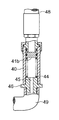
作動油の脈動を低減するものとして、従来、図5に示すようなサイドブランチ型共鳴管を使用するものが提案されている。(例えば、特許文献1参照)
図5において、アクチュエータ23は、図示しない原動機によって駆動される油圧ポンプ20から供給される作動油により、吐出管路24、コントロール弁22、負荷管路25を介して駆動される。
As a means for reducing the pulsation of hydraulic oil, conventionally, one using a side branch type resonance tube as shown in FIG. 5 has been proposed. (For example, see Patent Document 1)
In FIG. 5, the actuator 23 is driven via a
そして、油圧ポンプ20の吐出側または吐出管路24の途中には接続管47が介装されている。この接続管47には、吐出管路24に生じる脈動を低減する接続ホース48が接続されている。接続ホース48の先端側には、接続ホース48の全長を含む共鳴管路長Lを調整するために、ねじ調整式の管路長調整機構が設けられている。
A connecting
上述のねじ調整式の管路長調整機構は、シリンダ40と、シリンダ40内に摺動可能に挿嵌されたピストン41aと、ピストン41aをシリンダ40の長さ方向に移動させるねじ軸42とから構成されている。そして、ねじ軸42を回転させることにより、ねじ軸42に連結されたピストン41aをシリンダ40の長さ方向に移動させ、接続ホース48の全長を含む共鳴管路長Lを調整していると説明されている。なお、43は油孔である。
このような従来のものでは、作業員がその都度、ねじ軸42により共鳴管路長Lを調整する必要がある。
The above-described screw-adjustable pipe length adjusting mechanism includes a
In such a conventional apparatus, it is necessary for an operator to adjust the resonance pipe length L by the
そこで、図6に示すものも提案されている。(例えば、特許文献2参照)
図6に示すものは、接続ホース48の先端側には、接続ホース48の全長を含む共鳴管路長Lを調整するために、ばね調整式の管路長調整機構が設けられている。
Then, what is shown in FIG. 6 is also proposed. (For example, see Patent Document 2)
In the configuration shown in FIG. 6, a spring-adjustable pipe length adjustment mechanism is provided on the distal end side of the
このばね調整式の管路長調整機構は、シリンダ40と、シリンダ40内に摺動可能に挿嵌され油圧ポンプ20からの吐出圧に応じて変位することにより管路長を変化させるピストン41bと、ピストン41bを接続ホース48の開口端に向けて常時付勢する圧縮ばね44とから構成されている。
シリンダ40の先端は、ドレン管路49を介して図示しないタンクに接続されている。
なお、46はレデューサ、45は透孔である。
そして、油圧ポンプ20からの吐出圧によってピストン41bが、圧縮ばね44に抗してシリンダ40内を移動し、管路の長さを変化させていると説明されている。
This spring-adjustable pipe length adjusting mechanism includes a
The tip of the
In addition, 46 is a reducer and 45 is a through-hole.
Then, it is described that the
上述のサイドブランチ型共鳴管を使用する場合、共鳴管路長Lの4倍の長さの波長に近い周波数しか低減できないという性質を持っている。
一方、油圧ポンプがギアポンプ等の場合、油圧ポンプの回転数と作動油の流量とは比例するため、作動油の脈動の周波数は、作動油の流量に比例している。
従って、ギアポンプ等の場合、作動油の脈動の周波数と吐出圧とは比例関係にないので、広範囲の油圧ポンプの回転数の変動に対して、十分に作動油の脈動を低減することができないという問題がある。
When the above-described side branch type resonance tube is used, it has a property that only a frequency close to a wavelength having a length four times the resonance tube length L can be reduced.
On the other hand, when the hydraulic pump is a gear pump or the like, the rotational speed of the hydraulic pump is proportional to the flow rate of the hydraulic oil, so the frequency of pulsation of the hydraulic oil is proportional to the flow rate of the hydraulic oil.
Therefore, in the case of a gear pump or the like, since the frequency of hydraulic oil pulsation and the discharge pressure are not in a proportional relationship, the hydraulic oil pulsation cannot be sufficiently reduced with respect to fluctuations in the rotational speed of a wide range of hydraulic pumps. There's a problem.
本発明は、このような問題点を解決するために提案されたもので、ギアポンプ等を作動油の吐出源とした装置において、油圧管路中に絞り、ベンチュリ等を設け、その上流側と下流側との圧力差(流量増加にともない圧力差も増加)を利用してサイドブランチ型共鳴管の共鳴管路長を変化させることにより、脈動の広い範囲の周波数(回転数)を低減できる脈動低減装置を提供することを課題とする。 The present invention has been proposed in order to solve such problems. In an apparatus using a gear pump or the like as a hydraulic oil discharge source, a throttle, a venturi or the like is provided in the hydraulic line, and the upstream side and the downstream side thereof are provided. Pulsation reduction that can reduce the frequency (number of rotations) of a wide range of pulsations by changing the resonance channel length of the side branch type resonance tube using the pressure difference from the side (the pressure difference also increases with increasing flow rate) It is an object to provide an apparatus.
本発明は、上記の課題を解決するため、以下に示す手段を採用する。
第1の手段に係る脈動低減装置は、液圧回路における管路の途中に設けられた絞り手段と、内部に摺動可能なピストンを有するシリンダと、上記管路の上記絞り手段の一端側と上記シリンダの一端側とを接続する管路分岐手段と、上記管路の上記絞り手段の他端と上記シリンダの他端側とを接続する圧力取出手段と、上記シリンダの一端側内に設けられた弾性手段とを備えたことを特徴とする。
The present invention employs the following means in order to solve the above problems.
The pulsation reducing device according to the first means includes a throttle means provided in the middle of a pipeline in the hydraulic circuit, a cylinder having a piston slidable inside, and one end side of the throttle means in the pipeline. A pipe branching means for connecting one end side of the cylinder, a pressure extracting means for connecting the other end of the throttle means and the other end side of the cylinder, and one end side of the cylinder. And elastic means.
第2の手段に係る脈動低減油圧装置は、原動機によって吐出油量が制御される油圧ポンプと、該油圧ポンプの吐出側に接続された吐出管路と、該吐出管路の下流側に接続されたアクチュエータと、上記吐出管路の途中に設けられた絞り手段と、内部に摺動可能なピストンを有するシリンダと、上記絞り手段の下流側の上記吐出管路と上記シリンダの一端側とを接続する管路分岐手段と、上記絞り手段の上流側の上記吐出管路と上記シリンダの他端側とを接続する圧力取出手段と、上記シリンダの一端側内に設けられた弾性手段とを備えたことを特徴とする。 The pulsation reducing hydraulic device according to the second means is connected to a hydraulic pump whose discharge oil amount is controlled by a prime mover, a discharge pipe connected to the discharge side of the hydraulic pump, and a downstream side of the discharge pipe. Connecting the actuator, the throttle means provided in the middle of the discharge pipe, a cylinder having a piston slidable inside, and the discharge pipe downstream of the throttle means and one end of the cylinder A pipe branching means, a pressure extracting means for connecting the discharge pipe upstream of the throttle means and the other end side of the cylinder, and an elastic means provided in one end side of the cylinder It is characterized by that.
第3の手段に係る脈動低減油圧装置は、第2の手段において、上記絞り手段により上記管路分岐手段と圧力取出手段との間に、上記吐出管路内を流れる作動油の流量に応じた圧力差を発生させ、上記圧力差を上記管路分岐手段と上記圧力取出手段とを介して上記シリンダ内のピストンの両面に付加させ、付加された上記圧力差と上記弾性手段の弾性力とにより、上記ピストンから上記管路分岐手段の上記吐出管路の分岐点までの管路長を、上記吐出管路に流れる作動油の流量に応じて変化させる構成としたことを特徴とする。 The pulsation reducing hydraulic device according to the third means is the second means according to the flow rate of the hydraulic oil flowing in the discharge pipe between the pipe branching means and the pressure extracting means by the throttle means. A pressure difference is generated, the pressure difference is added to both surfaces of the piston in the cylinder via the pipe branching means and the pressure extracting means, and the added pressure difference and the elastic force of the elastic means The pipe length from the piston to the branch point of the discharge pipe of the pipe branching means is changed in accordance with the flow rate of hydraulic oil flowing through the discharge pipe.
第4の手段に係る脈動低減油圧装置は、原動機によって吐出油量が制御される油圧ポンプと、該油圧ポンプの吐出側に接続された吐出管路と、該吐出管路の下流側に接続されたアクチュエータと、上記吐出管路の途中に設けられたベンチュリと、内部中央部に仕切壁を有するシリンダと、上記仕切壁に穿設された透過孔と、上記シリンダ内の一端側に摺動可能に設けられた共鳴側ピストンヘッドと、上記シリンダ内の他端側に摺動可能に設けられた加圧側ピストンヘッドと、上記透過孔を液密且つ摺動可能に貫通し上記共鳴側ピストンヘッドと上記加圧側ピストンヘッドとを連結する連結棒と、上記仕切壁と上記加圧側ピストンヘッドとの間に設けられた弾性手段と上記ベンチュリの下流側の上記吐出管路と上記シリンダの一端側とを接続する管路分岐手段と、上記ベンチュリの上流側の上記吐出管路と上記シリンダの他端側及び上記シリンダの一端側の仕切壁近傍とを接続する圧力取出手段と、上記ベンチュリの中央部と上記シリンダの他端側の仕切壁近傍とを接続する負圧力取出手段とを備えたことを特徴とする。 A pulsation reducing hydraulic apparatus according to a fourth means is connected to a hydraulic pump whose discharge oil amount is controlled by a prime mover, a discharge pipe connected to a discharge side of the hydraulic pump, and a downstream side of the discharge pipe. Actuator, a venturi provided in the middle of the discharge pipe, a cylinder having a partition wall in the center of the inside, a transmission hole formed in the partition wall, and slidable on one end side in the cylinder A resonance-side piston head provided on the other end of the cylinder, a pressure-side piston head slidably provided on the other end side of the cylinder, and the resonance-side piston head penetrating through the permeation hole in a fluid-tight manner. A connecting rod for connecting the pressure side piston head, elastic means provided between the partition wall and the pressure side piston head, the discharge pipe downstream of the venturi, and one end side of the cylinder. Connect Pipe branching means, pressure discharge means for connecting the discharge pipe upstream of the venturi to the other end of the cylinder and the partition wall near one end of the cylinder, the central portion of the venturi, and the cylinder The negative pressure extraction means which connects the partition wall vicinity of the other end side of this is provided.
第5の手段に係る脈動低減油圧装置は、上記第2乃至4の手段において、上記油圧ポンプが定容量ポンプであることを特徴とする。 The pulsation reducing hydraulic apparatus according to the fifth means is characterized in that, in the second to fourth means, the hydraulic pump is a constant capacity pump.
第1の手段に係る脈動低減装置によれば、管路の絞り手段に液体が流れると、その液体の流量に応じて上流側と下流側とに圧力差が発生する。
この圧力差は管路分岐手段を介してシリンダの他端側に加圧され、ピストンを介して弾性手段を圧縮する。すると、ピストンはシリンダの一端側に押されて移動し、管路の分岐点からピストン迄の共鳴管路長が変化する。
このようにして、管路に流れる液体の量に対応して共鳴管路長は変化するため、管路に発生した脈動を低減することができる。
According to the pulsation reducing device according to the first means, when a liquid flows through the throttle means of the pipe line, a pressure difference is generated between the upstream side and the downstream side according to the flow rate of the liquid.
This pressure difference is pressurized to the other end of the cylinder via the pipe branching means, and compresses the elastic means via the piston. Then, the piston is pushed and moved toward one end of the cylinder, and the resonance pipe length from the branch point of the pipe to the piston changes.
In this way, since the resonance pipe length changes in accordance with the amount of liquid flowing in the pipe, pulsation generated in the pipe can be reduced.
第2、3の手段に係る脈動低減油圧装置において、油圧ポンプから吐出する作動油によりアクチュエータを駆動させると、吐出管路に脈動が発生する。
そして、油圧ポンプから吐出した作動油が吐出管路中の絞り手段を通過するとき、吐出油量に応じて上流側と下流側とに圧力差が発生する。この圧力差は圧力取出手段を介してシリンダの他端側に加圧され、ピストンを介して弾性手段を圧縮する。すると、ピストンはシリンダの一端側に押されて移動し、吐出管路の分岐点からピストン迄の共鳴管路長が変化する。
このようにして、吐出管路に流れる吐出油量に対応して共鳴管路長は変化するため、吐出管路に発生した脈動を低減することができる。
この結果、油圧管路に発生する騒音、流体音、噴流、キャビテーションを抑制し、油圧ポンプ、アクチュエータ、制御弁等の各油圧機器の損傷や寿命の低下を防止することができる。
In the pulsation reducing hydraulic device according to the second and third means, when the actuator is driven by the hydraulic oil discharged from the hydraulic pump, pulsation occurs in the discharge pipe.
When the hydraulic oil discharged from the hydraulic pump passes through the throttle means in the discharge pipe, a pressure difference is generated between the upstream side and the downstream side according to the amount of discharged oil. This pressure difference is pressurized to the other end side of the cylinder via the pressure extraction means, and compresses the elastic means via the piston. Then, the piston is pushed toward the one end side of the cylinder and moves, and the resonance pipe length from the branch point of the discharge pipe to the piston changes.
In this way, since the resonance line length changes corresponding to the amount of discharge oil flowing through the discharge line, pulsation generated in the discharge line can be reduced.
As a result, noise, fluid noise, jet flow, and cavitation generated in the hydraulic pipeline can be suppressed, and damage to each hydraulic device such as a hydraulic pump, actuator, and control valve, and a reduction in life can be prevented.
第4の手段に係る脈動低減油圧装置において、油圧ポンプから吐出する作動油によりアクチュエータを駆動させると、吐出管路に脈動が発生する。そして、油圧ポンプから吐出した作動油が吐出管路のベンチュリを通過するとき、吐出油量に応じて上流側と下流側とに圧力差が発生する。この圧力差は圧力取出手段を介してシリンダの他端側に加圧され、加圧側ピストンヘッド及び連結棒により加圧側ピストンヘッドに連結された共鳴側ピストンヘッドを介して圧縮ばねを圧縮する。
更に、吐出油量に応じてベンチュリの中央部にも負圧が発生しており、この負圧は負圧力取出手段を介してシリンダの仕切壁と加圧側ピストンヘッドとの間にも伝達され圧縮ばねを圧縮する。
すると、加圧側ピストンヘッド、連結棒及び共鳴側ピストンヘッドはシリンダの一端側に押されて移動し、吐出管路の分岐点からピストン迄の共鳴管路長が変化する。
このようにして、吐出管路に流れる吐出油量に対応して共鳴管路長は変化するため、吐出管路に発生した脈動を低減することができる。
この結果、油圧管路に発生する騒音、流体音、噴流、キャビテーションを抑制し、油圧ポンプ、アクチュエータ、制御弁等の各油圧機器の損傷や寿命の低下を防止することができる。
In the pulsation reducing hydraulic device according to the fourth means, when the actuator is driven by the hydraulic oil discharged from the hydraulic pump, pulsation occurs in the discharge pipe. When hydraulic oil discharged from the hydraulic pump passes through the venturi of the discharge pipe, a pressure difference is generated between the upstream side and the downstream side according to the amount of discharged oil. This pressure difference is pressurized to the other end side of the cylinder via the pressure extracting means, and the compression spring is compressed via the resonance side piston head connected to the pressure side piston head by the pressure side piston head and the connecting rod.
Furthermore, a negative pressure is also generated in the central portion of the venturi according to the amount of discharged oil. This negative pressure is also transmitted between the partition wall of the cylinder and the pressure side piston head via the negative pressure take-out means and compressed. Compress the spring.
Then, the pressure side piston head, the connecting rod, and the resonance side piston head are pushed and moved toward one end of the cylinder, and the resonance line length from the branch point of the discharge line to the piston changes.
In this way, since the resonance line length changes corresponding to the amount of discharge oil flowing through the discharge line, pulsation generated in the discharge line can be reduced.
As a result, noise, fluid noise, jet flow, and cavitation generated in the hydraulic pipeline can be suppressed, and damage to each hydraulic device such as a hydraulic pump, actuator, and control valve, and a reduction in life can be prevented.
第5の手段に係る脈動低減油圧装置によれば、第2乃至4の手段による効果に加えて、油圧ポンプがギアポンプ、ベーンポンプ、ピストンポンプ等の定容量型の油圧ポンプとすることにより、吐出管路に発生する脈動は吐出油量に応じたものとなるので、広範囲の周波数の脈動を抑制することができる。 According to the pulsation reducing hydraulic device of the fifth means, in addition to the effects of the second to fourth means, the hydraulic pump is a constant capacity type hydraulic pump such as a gear pump, vane pump, piston pump, etc., so that the discharge pipe Since the pulsation generated on the road corresponds to the amount of discharged oil, the pulsation in a wide range of frequencies can be suppressed.
本発明を実施するための最良の形態を以下の実施例1〜実施例4に基づき説明する。
図1は本発明の実施例1に係る騒音低減装置を有する油圧回路図、図2は本発明の実施例2に係る騒音低減装置を示す断面図である。図3は本発明の実施例3に係る騒音低減装置の断面図、図4は本発明の実施例4に係る騒音低減装置の断面図である。
The best mode for carrying out the present invention will be described based on the following first to fourth embodiments.
FIG. 1 is a hydraulic circuit diagram having a noise reduction apparatus according to Embodiment 1 of the present invention, and FIG. 2 is a cross-sectional view showing the noise reduction apparatus according to Embodiment 2 of the present invention. FIG. 3 is a cross-sectional view of a noise reduction apparatus according to Embodiment 3 of the present invention, and FIG. 4 is a cross-sectional view of the noise reduction apparatus according to Embodiment 4 of the present invention.
先ず、本発明に係る騒音低減装置の実施例1について、図1に基づき説明する。 First, a first embodiment of the noise reduction device according to the present invention will be described with reference to FIG.
図1に示すように、フォークリフト等においては、回転数を制御して吐出油量を変化させるギアポンプ、ベーンポンプ、ピストンポンプ等の定容量型の油圧ポンプ20が設けられている。この油圧ポンプ20は、図示しない原動機(ディーゼルエンジン、電動モータ等)により駆動されている。
そして、ディーゼルエンジンのクラッチ又は燃料スロットル、或いは電動モータの回転数を制御することにより、油圧ポンプ20の回転数は制御される。
As shown in FIG. 1, a forklift or the like is provided with a constant displacement
The rotational speed of the
この油圧ポンプ20からは、ディーゼルエンジン及び油圧ポンプ20の回転数に比例した高圧の作動油が吐出される。吐出された作動油は、油圧ポンプ20の吐出ポートに接続された上流側の吐出管路24a、吐出管路24aに接続された絞り手段10(絞り、ベンチュリ等)、絞り手段10に接続された下流側の吐出管路24b、及びコントロール弁22、負荷管路25を経由してシリンダ等のアクチュエータ23に供給される。
The
一方、アクチュエータ23からの戻り油は、負荷管路25、コントロール弁22、下流管路26、ドレン管路27を経由して作動油タンク28に排出される。
なお、下流側の吐出管路24bの途中には、ドレン管路27及びリリーフ弁21が分岐して接続されており、このリリーフ弁21が規定圧力で動作することにより、各機器が保護される。
On the other hand, the return oil from the actuator 23 is discharged to the
A
そして、下流側の吐出管路24bに発生している脈動を低減するために、絞り手段10の下流側の吐出管路24bの途中に、吐出管路24bから分岐する管路分岐手段12が設けられ、その管路分岐手段12の先端にシリンダ1の一端側が接続されている。この管路分岐手段12及びシリンダ1により、サイドブランチ型共鳴管が形成されている。
Further, in order to reduce the pulsation generated in the
一方、絞り手段10の上流側の吐出管路24aには、圧力取出手段11が接続され、その圧力取出手段11の先端はシリンダ1の他端側(加圧側)に接続されている。
このシリンダ1内には、ピストン2が摺動可能に設けられており、サイドブランチ型共鳴管の管路長を調整できるようになっている。
On the other hand, the pressure extraction means 11 is connected to the
A piston 2 is slidably provided in the cylinder 1 so that the length of the side branch type resonance tube can be adjusted.
そして、シリンダ1の一端側(共鳴側)には、ピストン2を他端側(加圧側)に押すように作用する弾性手段3が挿入されている。
一方、絞り手段10の作用により、上流側の吐出管路24a内の作動油の圧力と下流側の吐出管路24b内の作動油の圧力とには、作動油の流量に応じた圧力差が生じている。
An elastic means 3 is inserted on one end side (resonance side) of the cylinder 1 and acts to push the piston 2 toward the other end side (pressure side).
On the other hand, due to the action of the throttle means 10, there is a pressure difference according to the flow rate of the hydraulic oil between the pressure of the hydraulic oil in the
従って、シリンダ1の他端側(加圧側)には、圧力取出手段11にかかる吐出管路24aの作動油の圧力と管路分岐手段12にかかる吐出管路24b内の作動油の圧力との差圧が加圧される。この他端側(加圧側)に加圧された差圧力は、弾性手段3を圧縮する方向に、即ちピストン2を一端側(共鳴側)に押す方向に働く。
このようにして、ピストン2は、シリンダ1の一端側(共鳴側)の弾性手段3の弾性力と他端側(加圧側)にかかる圧力差とが均衡した位置、即ち吐出管路24bに流れる作動油の流量に対応した位置に移動する。
Therefore, on the other end side (pressurization side) of the cylinder 1, the pressure of the hydraulic oil in the
In this way, the piston 2 flows to the position where the elastic force of the elastic means 3 on one end side (resonance side) of the cylinder 1 is balanced with the pressure difference applied to the other end side (pressure side), that is, the
なお、絞り手段10の上流側の圧力取出手段11の位置における作動流体の圧力と、下流側の管路分岐手段12の位置における作動流体の圧力との圧力差(ΔP)、吐出管路24bに流れる作動油の流量(Q)は、次のような関係にある。
Q =K1√(ΔP)、K1は定数である。
なお、実機においては、絞り手段10の形状等の要因により、圧力差ΔPは、完全に流量Qの2乗に比例するものではない。
Note that the pressure difference (ΔP) between the pressure of the working fluid at the position of the pressure extraction means 11 upstream of the throttling means 10 and the pressure of the working fluid at the position of the downstream pipe branching means 12, the
Q = K 1 √ (ΔP), where K 1 is a constant.
In an actual machine, the pressure difference ΔP is not completely proportional to the square of the flow rate Q due to factors such as the shape of the throttle means 10.
一方、作動油の流量(Q)は、脈動の周波数、即ち油圧ポンプ20の回転数に比例している。
また、サイドブランチ型共鳴管の共鳴管路長であるシリンダ1の一端側の長さと管路分岐手段の長さとの合計の長さ(L)は、作動流体の脈動の波長の1/4とする必要がある。
そこで、弾性手段3を非線形特性のばね定数のものとすることにより、全或いは広範囲の周波数の脈動を低減できる。
なお、使用領域が限られている場合(アイドリングと全開を頻繁に使用する装置など)、或いは油圧システムにおいて脈動が最も大きくなる周波数域を抑制すれば良い場合には、通常の線形型特性のばね定数の弾性手段3でも、十分に所定の範囲の周波数域において脈動抑制効果が得られる。
On the other hand, the flow rate (Q) of the hydraulic oil is proportional to the pulsation frequency, that is, the rotational speed of the
The total length (L) of the length of one end of the cylinder 1 and the length of the pipe branching means, which is the resonance pipe length of the side branch type resonance pipe, is 1/4 of the wavelength of the pulsation of the working fluid. There is a need to.
Therefore, by using the elastic means 3 having a non-linear characteristic spring constant, it is possible to reduce the pulsation of all or a wide range of frequencies.
In addition, when the use area is limited (such as a device that frequently uses idling and full opening), or when it is sufficient to suppress the frequency range where the pulsation is the largest in a hydraulic system, a spring with a normal linear type characteristic is required. Even with the constant elastic means 3, a pulsation suppressing effect is sufficiently obtained in a predetermined frequency range.
上述の構成において、油圧ポンプ20から吐出する作動油をコントロール弁22により制御し、アクチュエータ23を駆動させると、吐出管路24a,24bに脈動が発生する。そして、油圧ポンプ20から吐出した作動油が、吐出管路24a,24bの途中に設けられた絞り手段10を通過するとき、吐出油の流量に応じて絞り手段10の上流側と下流側とに圧力差が発生する。
In the above configuration, when the hydraulic oil discharged from the
この圧力差は圧力取出手段11を介してシリンダ1の他端側に加圧され、ピストン2を介して弾性手段3を圧縮する。
すると、ピストン2はシリンダ1の一端側に押されて移動し、吐出管路24bの分岐点からピストン2迄の共鳴管路長、即ち、管路分岐手段12の長さとシリンダ1の弾性手段3が設置されている部分の長さの合計長が変化する。
This pressure difference is pressurized to the other end side of the cylinder 1 via the pressure extraction means 11 and compresses the elastic means 3 via the piston 2.
Then, the piston 2 is pushed and moved to one end side of the cylinder 1, and the resonance pipe length from the branch point of the
このようにして、吐出管路24a,24bに流れる吐出油量に対応して共鳴管路長Lは変化するため、吐出管路24a,24bに発生した全或いは広範囲の周波数の脈動は低減される。
この結果、吐出管路24a,24bに発生する騒音、流体音、噴流、キャビテーションを抑制し、油圧ポンプ20、アクチュエータ23、コントロール弁22、各管路24a,24b、25等の各油圧機器の損傷や寿命の低下を防止することができる。
In this way, since the resonance line length L changes corresponding to the amount of discharge oil flowing through the
As a result, noise, fluid noise, jet flow, and cavitation generated in the
次に、本発明に係る騒音低減装置の実施例2について、図2に基づき説明する。
なお、図2において、油圧ポンプ20、コントロール弁22、アクチュエータ23、リリーフ弁21、各管路等は、実施例1と同じであるので説明を省略する。また、実施例1と同一の部位については同一の符号を付して示している。
そこで、実施例1と異なる点について重点的に説明する。
Next, a second embodiment of the noise reduction device according to the present invention will be described with reference to FIG.
In FIG. 2, the
Therefore, differences from the first embodiment will be described mainly.
図2に示すように、吐出管路24aと吐出管路24bとの間には、絞り手段10としての絞り10aが配設されている。そして、絞り10aの下流側の吐出管路24bにシリンダ1aが垂直方向に立設されている。
なお、吐出管路24bとシリンダ1aの共鳴側4(一端側)の下端との接合部には、図示しない管路分岐手段としてのT字型分岐管12dが設けられている。
As shown in FIG. 2, a throttle 10a as the throttle means 10 is disposed between the
Note that a T-shaped branch pipe 12d as a pipe branching means (not shown) is provided at a joint between the
一方、絞り10aの上流側の吐出管路24aには、圧力取出手段11としての圧力取出管11dが接続されている。この圧力取出管11dの先端は、シリンダ1aの加圧側5(他端側)の上端に接続されている。
On the other hand, a pressure extraction pipe 11d as the pressure extraction means 11 is connected to the
シリンダ1a内には、シリンダ1a内を摺動するピストン2aが内蔵されている。
さらに、シリンダ1a内のピストン2aの下方の共鳴側4内には弾性手段3としての圧縮ばね3aが内蔵されている。
また、T字型分岐管12d内には、圧縮ばね3aを保持するためのストッパが設けられている。
A piston 2a that slides inside the cylinder 1a is built in the cylinder 1a.
Further, a compression spring 3a as an elastic means 3 is built in the resonance side 4 below the piston 2a in the cylinder 1a.
Further, a stopper for holding the compression spring 3a is provided in the T-shaped branch pipe 12d.
上述の構成において、図1に示す油圧ポンプ20から吐出された脈動を伴う高圧作動油が絞り10aを通過する時に、その上流側と下流側との間に作動油の流量の2乗に比例した圧力差が発生する。その圧力差は、圧力取出管11dを介して、シリンダ1aの加圧側5に伝達される。
この圧力差に応じて、ピストン2aを介して圧縮ばね3aは圧縮される。
In the above-described configuration, when the high-pressure hydraulic oil with pulsation discharged from the
In accordance with this pressure difference, the compression spring 3a is compressed via the piston 2a.
そして、ピストン1aは下方に移動し、サイドブランチ型共鳴管の共鳴管路長Lは変化する。このようにして、上述の本発明に係る騒音低減装置の実施例1と同様に、吐出管路24bに流れる作動油の流量に比例した共鳴管路長Lとなり、吐出管路24b内に発生した全或いは広範囲の周波数の脈動は抑制させられる。
この結果、吐出管路24a,24bに発生する騒音、流体音、噴流、キャビテーションを抑制し、各油圧機器の損傷や寿命の低下を防止することができる。
Then, the piston 1a moves downward, and the resonance line length L of the side branch type resonance tube changes. In this way, as in the first embodiment of the noise reduction device according to the present invention described above, the resonance line length L is proportional to the flow rate of the hydraulic oil flowing through the
As a result, noise, fluid noise, jet flow, and cavitation generated in the
本発明に係る騒音低減装置の実施例3について、図3に基づき説明する。
なお、図3において、油圧ポンプ20、コントロール弁22、アクチュエータ23、シリンダ1a、ピストン2a、圧縮ばね3a等は、実施例1、2と同じであるので説明を省略する。また、実施例1、2と同一の部位については同一の符号を付して示している。
そこで、実施例1、2と異なる点について重点的に説明する。
Embodiment 3 of the noise reduction device according to the present invention will be described with reference to FIG.
In FIG. 3, the
Therefore, differences from the first and second embodiments will be mainly described.
図3に示すように、シリンダ1aは略水平に設けられている。そして、絞り10aの下流側の吐出管路24bとシリンダ1aの共鳴側4(一端側)とは、管路分岐手段12としての分岐部材12a、管路延長ホース12b及び連結部材12cにより連結されている。
なお、連結部材12c内には、圧縮ばね3aを保持するための図示しないストッパが設けられている。
この場合、共鳴管路長Lは、分岐部材12a、管路延長ホース12b及び連結部材12cの各長さと、シリンダ1aの共鳴側4の長さとを合計したものとなる。
As shown in FIG. 3, the cylinder 1a is provided substantially horizontally. The
A stopper (not shown) for holding the compression spring 3a is provided in the connecting
In this case, the resonance pipe length L is the sum of the lengths of the branching
一方、絞り10aの上流側の吐出管路24aとシリンダ1aの加圧側5(他端側)とは、圧力取出手段11としての取出部材11a、接続ホース11b及び連結部材11cにより連結されている。
On the other hand, the
このような構成により、シリンダ1a、管路等の配置を自由に行うことが可能となる。そして、実施例1、2と同様に、図1に示す油圧ポンプ20から吐出された脈動を伴う高圧作動油が絞り10aを通過する時に、その上流側と下流側との間に作動油の流量の2乗に比例した圧力差が発生する。
With such a configuration, it is possible to freely arrange the cylinder 1a, the pipe line, and the like. As in the first and second embodiments, when the high pressure hydraulic oil with pulsation discharged from the
その圧力差は、取出部材11a、接続ホース11b及び連結部材11cを介して、シリンダ1aの加圧側5に伝達される。そして、この圧力差に応じて、ピストン2aを介して圧縮ばね3aは圧縮される。
The pressure difference is transmitted to the pressurizing side 5 of the cylinder 1a through the
このようにして、ピストン1aは共鳴側4に移動し、サイドブランチ型共鳴管の共鳴管路長Lは変化する。そして、上述の本発明に係る騒音低減装置の実施例1、2と同様に、共鳴管路長Lは、吐出管路24bに流れる作動油の流量に比例した長さとなり、吐出管路24b内に発生した全或いは広範囲の周波数の脈動は抑制させられる。
この結果、吐出管路24a,24bに発生する騒音、流体音、噴流、キャビテーションを抑制し、各油圧機器の損傷や寿命の低下を防止することができる。
In this way, the piston 1a moves to the resonance side 4, and the resonance line length L of the side branch type resonance tube changes. As in the first and second embodiments of the noise reduction device according to the present invention described above, the resonance line length L is proportional to the flow rate of the hydraulic oil flowing through the
As a result, noise, fluid noise, jet flow, and cavitation generated in the
次に、本発明に係る騒音低減装置の実施例4について、図4を用いて説明する。
なお、図4において、油圧ポンプ20、コントロール弁22、アクチュエータ23、管路分岐手段、圧力取出手段等は、実施例3と同じであるので説明を省略する。また、実施例3と同一の部位については同一の符号を付して示している。
そこで、実施例3と異なる点について重点的に説明する。
Next, a fourth embodiment of the noise reduction device according to the present invention will be described with reference to FIG.
In FIG. 4, the
Therefore, differences from the third embodiment will be described mainly.
図4に示すように、上流側吐出管路24aと下流側吐出管路24bとの間には、絞り手段10としてのベンチュリ10bが設けられている。即ち、実施例2、3における絞り10aの場合は圧力差分が損失となるが、ベンチュリ10bを採用することにより圧力損失を低減させることができる。
As shown in FIG. 4, a venturi 10b as the throttle means 10 is provided between the
シリンダ1bの中央には仕切壁6が設けられている。この仕切壁6の中心には、透過孔が穿設されている。そして、上記シリンダ1bの共鳴側4(一端側)内には、共鳴側ピストンヘッド7bが摺動可能に設けられ、共鳴側ピストンヘッド7bの図4中の右側は加圧作用側4bが形成され、左側は共鳴作用側4aが形成されている。
一方、シリンダ1bの加圧側5(他端側)内には、加圧側ピストンヘッド7aが摺動可能に設けられ、加圧側ピストンヘッド7aの図4中の右側は加圧作用側5aが形成され、左側は負圧作用側5bが形成されている。
A partition wall 6 is provided at the center of the cylinder 1b. A transmission hole is formed in the center of the partition wall 6. A resonance
On the other hand, a pressure
更に、シリンダ1b内において、連結棒7cが、仕切壁6の透過孔を液密且つ摺動可能に貫通して設けられている。この連結棒7cにより、共鳴側ピストンヘッド7bと上記加圧側ピストンヘッド7aが連結されている。
また、仕切壁6と加圧側ピストンヘッド7aとの間の負圧作用側5bには、圧縮ばね3aが配設されている。
Further, a connecting
A compression spring 3a is disposed on the negative
そして、ベンチュリ10bの上流側の吐出管路24aとシリンダ1bの加圧作用側5aとは、圧力取出手段11としての取出部材11a、接続ホース11b、11g及び連結部材11cにより連結されている。
一方、ベンチュリ10bの上流側の吐出管路24aとシリンダ1bの加圧作用側4bとも、接続ホース11bから分岐した接続ホース11e及び連結部材11fにより連結されている。
The
On the other hand, the
更に、本発明の実施例4においては、ベンチュリ10bの中央部とシリンダ1bの負圧作用側5bの仕切壁6近傍とは、負圧取出手段13としての、取出部材13a、接続ホース13b、連結部材13cにより接続されている。
Further, in the fourth embodiment of the present invention, the central portion of the venturi 10b and the vicinity of the partition wall 6 on the negative
本発明に係る騒音低減装置の実施例4は上述のごとく構成されており、油圧ポンプ20から吐出する作動油によりアクチュエータ23を駆動させると、吐出管路24a,24bに脈動が発生する。
The noise reduction device according to the fourth embodiment of the present invention is configured as described above. When the actuator 23 is driven by the hydraulic oil discharged from the
そして、油圧ポンプ20から吐出した作動油が吐出管路24a,24bのベンチュリ10bを通過するとき、吐出油量に応じてベンチュリ10bの上流側と下流側とに圧力差が発生する。この圧力差は、圧力取出手段11を介してシリンダの加圧作用側4b、5aに加圧され、加圧側ピストンヘッド7a及び、連結棒7cにより加圧側ピストンヘッド7aに連結された共鳴側ピストンヘッド7bを介して圧縮ばね3aを圧縮する。
When the hydraulic oil discharged from the
更に、吐出油量に応じてベンチュリ10bの中央部に負圧が発生しており、この負圧は負圧取出手段13を介してシリンダ1bの仕切壁6と加圧側ピストンヘッド7aとの間の負圧作用側5bにも伝達され圧縮ばね3aを圧縮する。
すると、加圧側ピストンヘッド7a、連結棒7c及び共鳴側ピストンヘッド7bはシリンダ1bの一端側に押されて移動し、吐出管路24bの分岐点から共鳴側ピストンヘッド7b迄の長さ、即ち管路分岐手段12の長さとシリンダ1bの共鳴側4の長さとの合計長であるの共鳴管路長Lは変化する。
このようにして、上述の本発明に係る騒音低減装置の実施例1と同様に、吐出管路24bに流れる作動油の流量に比例した共鳴管路長Lとなり、吐出管路24b内に発生した全或いは広範囲の周波数の脈動は抑制させられる。
この結果、吐出管路24a,24bに発生する騒音、流体音、噴流、キャビテーションを抑制し、各油圧機器の損傷や寿命の低下を防止することができる。
Furthermore, a negative pressure is generated in the central portion of the venturi 10b in accordance with the amount of discharged oil, and this negative pressure is interposed between the partition wall 6 of the cylinder 1b and the pressure
Then, the pressure
In this manner, similarly to the first embodiment of the noise reduction device according to the present invention described above, the resonance line length L is proportional to the flow rate of the hydraulic oil flowing through the
As a result, noise, fluid noise, jet flow, and cavitation generated in the
以上、本発明を図示の各実施例について説明したが、本発明は上記の各実施例に限定されず、本発明の範囲内でその具体的構造に種々の変更を加えてよいことはいうまでもない。
例えば、図2〜図4に示すものにおいて、吐出管路24a、24bの両端に接続ジョイントを設けたものをユニット化しておけば、既存の油圧装置に簡単に挿入、接続し、脈動低減対策を行うことができる。
Although the present invention has been described with reference to the illustrated embodiments, the present invention is not limited to the above-described embodiments, and various modifications may be made to the specific structure within the scope of the present invention. Nor.
For example, in the case shown in FIGS. 2 to 4, if the
また、図2のものにおいて、シリンダ1aは吐出管路24bに垂直方向に立設したものに限定されるものではなく、斜め方向でも、下方に設けるようにしても良い。
更には、図2のものにおいて、上流側の吐出管路24a及び絞り10aと同一直線状にシリンダ1aを接続し、下流側の吐出管路24bを直角に分岐して接続するようにしても良い。
Further, in FIG. 2, the cylinder 1a is not limited to the cylinder 1a provided upright in the direction perpendicular to the
Furthermore, in FIG. 2, the cylinder 1a may be connected in a straight line with the
弾性手段としては、圧縮式のものに限らず、シリンダ1aの加圧側5に設けることも可能である。この弾性手段も、コイルばねに限らず、板ばねを積層したもの、等も使用可能である。
更に、各実施例に係る脈動低減装置は、油圧装置に限らず、空気圧装置等、各種の流体圧装置に採用可能である。
The elastic means is not limited to the compression type, and can be provided on the pressure side 5 of the cylinder 1a. This elastic means is not limited to a coil spring, and a laminated plate spring can be used.
Furthermore, the pulsation reducing device according to each embodiment is not limited to a hydraulic device, and can be employed in various fluid pressure devices such as a pneumatic device.
1、1a、1b シリンダ
2、2a、2b ピストン
3 弾性手段
3a 圧縮ばね
4 共鳴側
4a 共鳴作用側
4b 加圧作用側
5 加圧側
5a 加圧作用側
5b 負圧作用側
6 仕切壁
7a 加圧側ピストンヘッド
7b 共鳴側ピストンヘッド
7c 連結棒
10 絞り手段
10a 絞り
10b ベンチュリ
11 圧力取出手段
11a 取出部材
11b、11g、11e 接続ホース
11c、11f 連結部材
11d 圧力取出管
12 管路分岐手段
12a 分岐部材
12b 管路延長ホース
12c 連結部材
12d T字型分岐管
13 負圧取出手段
13a 取出部材
13b 接続ホース
13c 連結部材
20 油圧ポンプ
21 リリーフ弁
22 コントロール弁
23 アクチュエータ
24、24a、24b 吐出管路
25 負荷管路
26 下流管路
27 ドレン管路
28 作動油タンク
40 シリンダ
41a、41b ピストン
42 ねじ軸
43 油孔
44 圧縮ばね
45 透孔
46 レデューサ
47 接続管
48 接続ホース
49 ドレン管路
L 共鳴管路長
DESCRIPTION OF SYMBOLS 1, 1a, 1b Cylinder 2, 2a, 2b Piston 3 Elastic means 3a Compression spring 4
Claims (5)
Priority Applications (1)
| Application Number | Priority Date | Filing Date | Title |
|---|---|---|---|
| JP2004006863A JP2005201323A (en) | 2004-01-14 | 2004-01-14 | Pulsation reducing device or pulsation reducing hydraulic device |
Applications Claiming Priority (1)
| Application Number | Priority Date | Filing Date | Title |
|---|---|---|---|
| JP2004006863A JP2005201323A (en) | 2004-01-14 | 2004-01-14 | Pulsation reducing device or pulsation reducing hydraulic device |
Publications (1)
| Publication Number | Publication Date |
|---|---|
| JP2005201323A true JP2005201323A (en) | 2005-07-28 |
Family
ID=34820708
Family Applications (1)
| Application Number | Title | Priority Date | Filing Date |
|---|---|---|---|
| JP2004006863A Withdrawn JP2005201323A (en) | 2004-01-14 | 2004-01-14 | Pulsation reducing device or pulsation reducing hydraulic device |
Country Status (1)
| Country | Link |
|---|---|
| JP (1) | JP2005201323A (en) |
Cited By (9)
| Publication number | Priority date | Publication date | Assignee | Title |
|---|---|---|---|---|
| JP2005249118A (en) * | 2004-03-05 | 2005-09-15 | Aichi Corp | Pressure control valve |
| JP2007303551A (en) * | 2006-05-11 | 2007-11-22 | Kobelco Contstruction Machinery Ltd | Pressure relief method and pressure relief device for hydraulic piping |
| JP2017015068A (en) * | 2015-07-06 | 2017-01-19 | 渡部 富治 | Wind power/wave power generation machine/hydraulic complex transmission |
| CN112855671A (en) * | 2021-01-04 | 2021-05-28 | 中联重科股份有限公司 | Oil supply pipeline for hydraulic system and hydraulic system |
| CN113776724A (en) * | 2021-08-12 | 2021-12-10 | 中国船舶重工集团公司第七一九研究所 | Pressure measuring device |
| JP2022128609A (en) * | 2021-02-24 | 2022-09-05 | 三菱重工業株式会社 | Hydraulic control system, and control method for hydraulic device |
| US11585154B2 (en) | 2017-09-08 | 2023-02-21 | Epiroc Rock Drills Aktiebolag | Mining or construction vehicle |
| US11661797B2 (en) | 2017-09-08 | 2023-05-30 | Epiroc Rock Drills Aktiebolag | Mining or construction vehicle and a hydraulic cylinder conduit enclosing a conduit arrangement |
| US11731603B2 (en) | 2019-07-31 | 2023-08-22 | Toyota Jidosha Kabushiki Kaisha | Pipeline and braking system |
-
2004
- 2004-01-14 JP JP2004006863A patent/JP2005201323A/en not_active Withdrawn
Cited By (11)
| Publication number | Priority date | Publication date | Assignee | Title |
|---|---|---|---|---|
| JP2005249118A (en) * | 2004-03-05 | 2005-09-15 | Aichi Corp | Pressure control valve |
| JP2007303551A (en) * | 2006-05-11 | 2007-11-22 | Kobelco Contstruction Machinery Ltd | Pressure relief method and pressure relief device for hydraulic piping |
| JP2017015068A (en) * | 2015-07-06 | 2017-01-19 | 渡部 富治 | Wind power/wave power generation machine/hydraulic complex transmission |
| US11585154B2 (en) | 2017-09-08 | 2023-02-21 | Epiroc Rock Drills Aktiebolag | Mining or construction vehicle |
| US11661797B2 (en) | 2017-09-08 | 2023-05-30 | Epiroc Rock Drills Aktiebolag | Mining or construction vehicle and a hydraulic cylinder conduit enclosing a conduit arrangement |
| US11731603B2 (en) | 2019-07-31 | 2023-08-22 | Toyota Jidosha Kabushiki Kaisha | Pipeline and braking system |
| CN112855671A (en) * | 2021-01-04 | 2021-05-28 | 中联重科股份有限公司 | Oil supply pipeline for hydraulic system and hydraulic system |
| JP2022128609A (en) * | 2021-02-24 | 2022-09-05 | 三菱重工業株式会社 | Hydraulic control system, and control method for hydraulic device |
| JP7315599B2 (en) | 2021-02-24 | 2023-07-26 | 三菱重工業株式会社 | Hydraulic control system, control method for hydraulic equipment |
| CN113776724A (en) * | 2021-08-12 | 2021-12-10 | 中国船舶重工集团公司第七一九研究所 | Pressure measuring device |
| CN113776724B (en) * | 2021-08-12 | 2024-05-14 | 中国船舶重工集团公司第七一九研究所 | Pressure measuring device |
Similar Documents
| Publication | Publication Date | Title |
|---|---|---|
| Chapple | Principles of hydraulic systems design | |
| CN102011767B (en) | Hydraulic system | |
| CN101688544B (en) | Fluid pressure drive unit and snow removal unit | |
| WO2008123376A1 (en) | Controller of vehicle with hydrostatic continuously variable transmission | |
| CN101688546A (en) | Hydraulic system with external pressure compensator | |
| JP2005201323A (en) | Pulsation reducing device or pulsation reducing hydraulic device | |
| CN102859081A (en) | Pump suction charging system | |
| EP3152445B1 (en) | Hydraulic cylinder | |
| US6862972B2 (en) | Additive injection device | |
| WO2014015903A1 (en) | Subsea hydraulic power unit | |
| US20180291797A1 (en) | Hydraulic system for maintaining minimum low side pressure of closed circuit hydraulic system | |
| JP5442914B1 (en) | Pipe layer | |
| CN112112867B (en) | Hydraulic exhaust valve unit, hydraulic exhaust winch control system and winch | |
| CN112343881B (en) | Balanced pressure self preservation protects hydraulic system | |
| US8443827B2 (en) | Controlling device for hydraulic consumers | |
| CN102650303A (en) | Power drives for concrete pumping equipment and concrete pumping equipment | |
| JP3891616B2 (en) | Input torque control circuit for variable displacement pump | |
| CN108975188A (en) | A kind of hydraulic system | |
| CN109026861A (en) | A kind of universal decompressor of ship hydraulic system and decompression method | |
| JP5991950B2 (en) | Hydraulic circuit for construction machinery | |
| JPH10110704A (en) | Hydraulic control device | |
| JP3798882B2 (en) | Hammer shovel | |
| CN112814964A (en) | Valveless reversing device and method | |
| KR100734442B1 (en) | Hydraulic circuit for driving straight | |
| JP2012242259A (en) | Hydraulic controller and test machine including the hydraulic controller |
Legal Events
| Date | Code | Title | Description |
|---|---|---|---|
| A300 | Withdrawal of application because of no request for examination |
Free format text: JAPANESE INTERMEDIATE CODE: A300 Effective date: 20070403 |