JP2005207331A - Exhaust muffler apparatus - Google Patents
Exhaust muffler apparatus Download PDFInfo
- Publication number
- JP2005207331A JP2005207331A JP2004015312A JP2004015312A JP2005207331A JP 2005207331 A JP2005207331 A JP 2005207331A JP 2004015312 A JP2004015312 A JP 2004015312A JP 2004015312 A JP2004015312 A JP 2004015312A JP 2005207331 A JP2005207331 A JP 2005207331A
- Authority
- JP
- Japan
- Prior art keywords
- chamber
- exhaust
- pipe
- partition
- muffler device
- Prior art date
- Legal status (The legal status is an assumption and is not a legal conclusion. Google has not performed a legal analysis and makes no representation as to the accuracy of the status listed.)
- Pending
Links
- 238000005192 partition Methods 0.000 claims abstract description 44
- 238000000746 purification Methods 0.000 claims abstract description 38
- 238000004891 communication Methods 0.000 claims description 44
- 238000011144 upstream manufacturing Methods 0.000 claims description 12
- 239000011358 absorbing material Substances 0.000 claims description 6
- 230000002093 peripheral effect Effects 0.000 claims description 5
- 230000000149 penetrating effect Effects 0.000 claims 1
- 230000000694 effects Effects 0.000 description 11
- 230000002238 attenuated effect Effects 0.000 description 9
- 239000003054 catalyst Substances 0.000 description 9
- 230000001743 silencing effect Effects 0.000 description 9
- 239000011491 glass wool Substances 0.000 description 8
- 238000000034 method Methods 0.000 description 8
- 238000006722 reduction reaction Methods 0.000 description 5
- 241000264877 Hippospongia communis Species 0.000 description 4
- 230000008569 process Effects 0.000 description 4
- 230000009467 reduction Effects 0.000 description 4
- 238000004080 punching Methods 0.000 description 3
- 238000010521 absorption reaction Methods 0.000 description 2
- 238000013461 design Methods 0.000 description 2
- 230000030279 gene silencing Effects 0.000 description 2
- 239000000463 material Substances 0.000 description 2
- 239000002184 metal Substances 0.000 description 2
- 230000003647 oxidation Effects 0.000 description 2
- 238000007254 oxidation reaction Methods 0.000 description 2
- 230000001902 propagating effect Effects 0.000 description 2
- 229910001220 stainless steel Inorganic materials 0.000 description 2
- 239000010935 stainless steel Substances 0.000 description 2
- 239000000126 substance Substances 0.000 description 2
- 230000009471 action Effects 0.000 description 1
- 230000000052 comparative effect Effects 0.000 description 1
- 229910052878 cordierite Inorganic materials 0.000 description 1
- 238000005260 corrosion Methods 0.000 description 1
- 230000007797 corrosion Effects 0.000 description 1
- 238000010586 diagram Methods 0.000 description 1
- JSKIRARMQDRGJZ-UHFFFAOYSA-N dimagnesium dioxido-bis[(1-oxido-3-oxo-2,4,6,8,9-pentaoxa-1,3-disila-5,7-dialuminabicyclo[3.3.1]nonan-7-yl)oxy]silane Chemical compound [Mg++].[Mg++].[O-][Si]([O-])(O[Al]1O[Al]2O[Si](=O)O[Si]([O-])(O1)O2)O[Al]1O[Al]2O[Si](=O)O[Si]([O-])(O1)O2 JSKIRARMQDRGJZ-UHFFFAOYSA-N 0.000 description 1
- 238000007599 discharging Methods 0.000 description 1
- 238000011038 discontinuous diafiltration by volume reduction Methods 0.000 description 1
- 230000002708 enhancing effect Effects 0.000 description 1
- 238000002474 experimental method Methods 0.000 description 1
- 230000012447 hatching Effects 0.000 description 1
- 238000012986 modification Methods 0.000 description 1
- 230000004048 modification Effects 0.000 description 1
- 229910021426 porous silicon Inorganic materials 0.000 description 1
- 238000012805 post-processing Methods 0.000 description 1
- 230000000644 propagated effect Effects 0.000 description 1
- HBMJWWWQQXIZIP-UHFFFAOYSA-N silicon carbide Chemical compound [Si+]#[C-] HBMJWWWQQXIZIP-UHFFFAOYSA-N 0.000 description 1
- 238000012360 testing method Methods 0.000 description 1
Images


Landscapes
- Exhaust Gas After Treatment (AREA)
- Exhaust Silencers (AREA)
Abstract
Description
本発明は、排気マフラ装置本体に排気浄化手段を収納した形態の排気マフラ装置に関するものである。 The present invention relates to an exhaust muffler device having an exhaust purification means housed in an exhaust muffler device body.
一般に、機関、例えば、ディーゼル機関の排気ガスを後処理する装置としての排気浄化手段には、触媒モノリスあるいはパティキュレートフィルターといった形態のものがあるが、かかる排気浄化手段の浄化効率は、高温雰囲気中で動作させるのが有効であることが知られている。このため、排気浄化手段を排気マフラ本体内部の高温雰囲気中に設置する形態の排気マフラ装置の開発が要請される。 In general, exhaust purification means as an apparatus for post-processing exhaust gas of an engine, for example, a diesel engine, has a form such as a catalyst monolith or a particulate filter. The purification efficiency of such exhaust purification means is high in a high-temperature atmosphere. It is known that it is effective to operate with this. For this reason, it is required to develop an exhaust muffler apparatus in which the exhaust purification means is installed in a high temperature atmosphere inside the exhaust muffler body.
排気マフラ本体内に、触媒モノリスまたはパティキュレートフィルターでなる浄化手段を収納した排気マフラ装置として、例えば、特開2002−21531号公報記載の技術(以下、「従来技術」という)が公知である。すなわち、この従来技術は、図9に示すように、排気マフラ装置の本体を2つの第1隔壁1,第2隔壁2により第1室3,第2室4,第3室5に仕切り、両隔壁1,2間に跨るように第2室4に浄化手段6を上下二段にした状態で取り付けている。また、排気マフラ本体には、第1室3に連通する入口パイプ7、第2室4と第3室5とに跨るインナパイプ8(上下方向に2本)、このインナパイプ8よりも長い寸法を有して排気マフラ本体を貫通するように存置した出口パイプ9が設けられている。上記インナパイプ8と出口パイプ9には、それぞれ第2室4、第3室5に連通する孔8a、9aが、また、第2隔壁2にも、第2室4と第3室5が連通するように孔2aがそれぞれ形成されている。
As an exhaust muffler apparatus in which a purifying means made of a catalyst monolith or a particulate filter is housed in an exhaust muffler body, for example, a technique described in Japanese Patent Application Laid-Open No. 2002-21431 (hereinafter referred to as “prior art”) is known. That is, in this prior art, as shown in FIG. 9, the main body of the exhaust muffler device is divided into a first chamber 3, a second chamber 4, and a
このように、上記従来技術は、機関からの排気ガスは、入口パイプ7から第1室3に導入されて膨脹した後、浄化手段6を流動することで排気ガスを浄化し、第3室5に流入して膨脹する。第3室5に放出された排気ガスは、インナパイプ8に流入し孔8aから第2室2に放出され、所定の音域のノイズを消音するようにしたものである。そして、第2室2に流入した排気ガスは、出口パイプ9の孔(第2室4に臨む孔)9aに吸引されて出口パイプ9内に導入され、外部へ排出していくようになっている。
As described above, in the above prior art, the exhaust gas from the engine is introduced into the first chamber 3 from the
しかしながら、上記従来技術にあっては、排気ガスの流路を第1室3および第3室5だけでなく、浄化手段6周囲の第2室4をも排気ガスの容積を膨脹させる膨脹室として活用し、これら室3,4,5に排気ガスを流動させて拡散、絞り込みを繰り返しながら音同士を干渉させ、排気騒音を減衰するようにしているものの、排気騒音源のもう一方の要因である排気音の流れに着目した共鳴室を設けた構造による騒音低減を図ったものではないため、或る排気マフラ装置における特定周波数域の排気音の減衰効果には一定の限界があった。
However, in the above-described prior art, not only the first chamber 3 and the
かかる排気音の流れに着目して共鳴室を設けることにより排気騒音を減衰させる技術として、例えば、特開平10−274027号公報に記載されているように、共鳴室とそれに連通する枝管とでなるヘルムホルツ共鳴器の原理を利用して共鳴周波数付近で最大の減音量を得るようにした排気マフラ装置を設計することが考えられる。なお、上記特開平10−274027号公報に記載された技術には、ただ単に排気管の途中にヘルムホルツ型の共鳴装置を設けただけの構造に過ぎず、排気浄化手段を排気マフラ装置本体に収納して、その排気マフラ装置に特有の特定周波数域の排気音を消音するようにした技術ではない。 As a technique for attenuating exhaust noise by providing a resonance chamber focusing on the flow of such exhaust sound, for example, as described in JP-A-10-274027, a resonance chamber and a branch pipe communicating with the resonance chamber are used. It is conceivable to design an exhaust muffler device that obtains the maximum volume reduction near the resonance frequency by utilizing the principle of the Helmholtz resonator. The technique described in Japanese Patent Laid-Open No. 10-274027 is merely a structure in which a Helmholtz type resonance device is provided in the middle of the exhaust pipe, and the exhaust purification means is housed in the exhaust muffler device body. Thus, it is not a technique that silences the exhaust sound in a specific frequency range unique to the exhaust muffler device.
本出願人は、排気マフラ装置本体内に排気浄化手段を内装した排気マフラ装置において、排気浄化効率を向上させることができるだけでなく、排気騒音をも有効に低減できる排気マフラ装置の研究・開発を行ってきた。その結果、上記特許文献1の公報に記載された従来装置の有する問題を解決するためには、上記特許文献2の公報にも記載されているヘルムホルツ共鳴器の原理を応用することで、排気音の音の流れに対する消音効果を高めることが可能であるとの知見を見いだすことができ、排気浄化効率の向上はもちろんのこと、同時に排気騒音をも円滑に低減できる排気マフラ装置を開発することができた。本発明は、かかる排気マフラ装置を提供することを目的(課題)とする。
The present applicant has researched and developed an exhaust muffler device that not only improves exhaust purification efficiency but also can effectively reduce exhaust noise in an exhaust muffler device having exhaust purification means incorporated in the exhaust muffler body. I went. As a result, in order to solve the problems of the conventional device described in the publication of the above-mentioned patent document 1, by applying the principle of the Helmholtz resonator described in the publication of the above-mentioned
上記課題を解決するために、本発明においては次のような手段を講ずることとした。すなわち、請求項1記載の発明は、排気マフラ装置であって、筒状の外殻両端開口部を上流側エンドプレートおよび下流側エンドプレートにより閉塞して形成した排気マフラ装置本体において、同排気マフラ装置本体内部に設けた第1隔壁および第2隔壁と、前記下流側エンドプレートと前記第1隔壁とで仕切られた膨脹室としての第1室と、前記第1隔壁と前記第2隔壁とで仕切られた共鳴室としての第2室と、前記第2隔壁と前記上流側エンドプレートとで仕切られた膨脹室としての第3室と、前記排気マフラ装置本体内に収納され、上流側を前記上流側エンドプレートに設けた排気入口管に下流側を前記第1室に開口させた排気浄化手段と、前記第2室を貫通すると共に、一端が前記第1室に開口され他端をパンチ孔を介して前記第3室に連通する第1の連通管と、前記第1の連通管に平行配置されて前記第2室を貫通し、一端が前記第1室に開口され他端を前記第3室に開口させた第2の連通管と、前記第3室へ所定長さの寸法で突出するように前記第2隔壁に設けられ、前記第3室から前記第2室へ音の流れを流入させる枝管と、前記第2隔壁に形成され、前記第2室から前記第3室へ音の流れを流入させる穴部と、前記上流側エンドプレートに設けられ、前記第3室の排気を外部へ放出する排気出口管とを具備したことを特徴とする。 In order to solve the above problems, the following measures are taken in the present invention. That is, the invention according to claim 1 is an exhaust muffler device, wherein the exhaust muffler device body is formed by closing the cylindrical outer shell both end openings with the upstream end plate and the downstream end plate. A first partition and a second partition provided inside the apparatus main body, a first chamber as an expansion chamber partitioned by the downstream end plate and the first partition, the first partition and the second partition A second chamber as a partitioned resonance chamber, a third chamber as an expansion chamber partitioned by the second partition wall and the upstream end plate, and the exhaust muffler main body are housed in an upstream side, Exhaust gas purifying means having a downstream side opened to the first chamber in an exhaust inlet pipe provided on the upstream side end plate, and one end opened to the first chamber and the other end punched through the second chamber Through the third A first communication pipe that communicates with the first communication pipe, and a first communication pipe that is arranged in parallel with the first communication pipe and penetrates the second chamber, and has one end opened in the first chamber and the other end opened in the third chamber. Two communication pipes, a branch pipe provided in the second partition so as to protrude into the third chamber with a dimension of a predetermined length, and allowing the flow of sound from the third chamber to the second chamber, A hole formed in the second partition wall for allowing sound to flow from the second chamber to the third chamber, and an exhaust outlet pipe provided in the upstream end plate for discharging the exhaust from the third chamber to the outside It was characterized by comprising.
この請求項1記載の発明では、ディーゼルエンジンあるいはガソリンエンジン等から排出された排気ガスは、排気入口管から排気マフラ装置本体内に流入し、ディーゼルパティキュレートフィルターや触媒モノリスといったハニカム構造を有する排気浄化手段を流通する。排気ガスが排気浄化手段を通過するとき、排気ガス中の有害成分は捕捉されて浄化された後、第1室で拡散膨脹する。第1室の排気ガス流れの大部分は、第2の連通管(両端は開口しているが、パンチ孔は形成されていない管)に絞り込まれて入った後、第3室に一旦流れ込み、排気出口管から外部へ排出されていく。このとき、第2の連通管は気柱共鳴をするので、共鳴周波数に等しい振動成分が干渉により減衰されるようになる。また、第1室における排気ガスの流れの一部は、第1の連通管にも絞り込まれて流入し第3室に臨むパンチ孔から第3室に流出して拡散膨脹した後、排気出口管から排出されていく。他方、第3室の排気ガス中における排気音の流れ(排気ガスの流れではない)に着目すると、様々な周波数成分を含んだ排気音の流れは、第2隔壁に突出するように設けた枝管から第2室に伝播して入り込んだ後、さらに第2隔壁に設けた穴部から第3室に伝播していく。こうして、排気音の流れが、枝管から第3室に入った後、穴部から第3室へ伝播していく過程で、第2室がヘルムホルツ共鳴室として機能しているので、共鳴周波数付近の成分、つまり排気音の特定周波数域における成分が減衰(消音)され、第2室内で排気音が消音されるようになる。 According to the first aspect of the present invention, exhaust gas discharged from a diesel engine or gasoline engine or the like flows into the exhaust muffler body from an exhaust inlet pipe, and has an exhaust purification structure having a honeycomb structure such as a diesel particulate filter or a catalyst monolith. Circulate means. When the exhaust gas passes through the exhaust gas purification means, harmful components in the exhaust gas are captured and purified, and then diffused and expanded in the first chamber. Most of the exhaust gas flow in the first chamber is squeezed into the second communication pipe (a pipe having both ends open but no punch holes are formed), and then flows into the third chamber. It is discharged from the exhaust outlet pipe to the outside. At this time, since the second communication pipe performs air column resonance, a vibration component equal to the resonance frequency is attenuated by interference. Further, a part of the flow of the exhaust gas in the first chamber is squeezed into the first communication pipe and flows into the third chamber from the punch hole facing the third chamber and diffuses and expands, and then the exhaust outlet pipe It will be discharged from. On the other hand, focusing on the flow of exhaust sound in the exhaust gas in the third chamber (not the flow of exhaust gas), the flow of exhaust sound including various frequency components is provided so as to protrude into the second partition wall. After propagating from the tube into the second chamber and entering the second chamber, it further propagates from the hole provided in the second partition to the third chamber. Thus, after the flow of the exhaust sound enters the third chamber from the branch pipe and then propagates from the hole to the third chamber, the second chamber functions as a Helmholtz resonance chamber. Component, that is, a component in a specific frequency range of the exhaust sound is attenuated (silenced), and the exhaust sound is silenced in the second chamber.
また、請求項2記載の発明は、請求項1記載の発明に係り、前記枝管から前記第2室へ突出する延長管を設け、同延長管の管端を閉塞するとともに、同延長管の前記第2室内における周壁にパンチ孔を形成したことを特徴とする。
Further, the invention according to
この請求項2記載の発明では、枝管に延長して設けた延長管にパンチ孔を形成しているので、パンチ孔から第2室に流入した排気ガスは、第2室で膨脹拡散するため、排気ガスは、第2室でも減音されるようになる。 According to the second aspect of the present invention, since the punch hole is formed in the extension pipe provided to extend from the branch pipe, the exhaust gas flowing into the second chamber from the punch hole is expanded and diffused in the second chamber. The exhaust gas is also reduced in the second chamber.
また、請求項3記載の発明は、請求項1または2記載の排気マフラ装置に係り、前記第2の連通管の前記第3室における開口端を、前記排気出口管近傍まで延長したことを特徴とする。
The invention according to claim 3 relates to the exhaust muffler device according to
この請求項3記載の発明では、第2の連通管(パンチ孔は設けられていない)の開口端が、第3室において排気出口管に近接して設けられている、つまり、上流側エンドプレートに近接した位置で開口しているので、第1室の排気ガスをダイレクトに第2の連通管を介して第3室に導かれた後、排気出口管から排出させることができ、第3室に負圧を生じさせるようにして、第1室の排気ガスが第1の連通管に流入するようにしている。 In the invention according to claim 3, the open end of the second communication pipe (no punch hole is provided) is provided in the third chamber close to the exhaust outlet pipe, that is, the upstream end plate Since the exhaust gas in the first chamber is directly guided to the third chamber through the second communication pipe, the first chamber can be discharged from the exhaust outlet pipe. The exhaust gas in the first chamber flows into the first communication pipe so as to generate a negative pressure.
また、請求項4記載の発明は、請求項1乃至3のいずれか一項に記載の排気マフラ装置に係り、前記排気マフラ装置本体の下流の排気管に、内筒と外筒とで形成されたサブマフラ装置の前記内筒を連通し、前記内筒に直径が略4mmの多数のパンチ孔を穿ち、かつ、前記内外両筒内の室に密度が略120g/cm3の吸音材を充填したことを特徴とする。 According to a fourth aspect of the present invention, there is provided the exhaust muffler device according to any one of the first to third aspects, wherein an exhaust pipe downstream of the exhaust muffler main body is formed of an inner cylinder and an outer cylinder. The inner cylinder of the sub-muffler device is communicated, the inner cylinder is provided with a number of punch holes having a diameter of about 4 mm, and the chambers in the inner and outer cylinders are filled with a sound absorbing material having a density of about 120 g / cm3. It is characterized by.
この請求項4記載の発明では、排気マフラ装置本体下流の排気管に設けたサブマフラ装置を排気ガスが流れるとき、内筒のパンチ孔から内外両筒で形成された室に膨脹拡散して流れ込むので、例えばグラスウール等の吸音材で騒音が吸収される。 In the invention according to claim 4, when exhaust gas flows through the sub-muffler device provided in the exhaust pipe downstream of the exhaust muffler device main body, the exhaust gas diffuses and flows from the punch hole of the inner cylinder into the chamber formed by both the inner and outer cylinders. The noise is absorbed by a sound absorbing material such as glass wool.
また、請求項5記載の発明は、請求項1乃至4のいずれか一項に記載の排気マフラ装置に係り、前記排気入口管と前記排気浄化手段との間に、前記排気浄化手段に向かうに応じて排気流通断面積が拡大するラッパ状管を設けたことを特徴とする。
The invention according to
この請求項5記載の発明では、排気入口管からラッパ状管を経由して排気浄化手段にそのまま流入するので、排気浄化手段を高温に保持した状態で浄化作用を行うため、浄化効率を維持することが可能であるとともに、排気ガスがラッパ状管を流動するときに、排気ガスは膨脹拡散され、排気騒音の低減に有利となる。 According to the fifth aspect of the present invention, since the exhaust gas is directly supplied from the exhaust inlet pipe to the exhaust gas purification means via the trumpet-like pipe, the purification efficiency is maintained because the purification action is performed while the exhaust gas purification means is kept at a high temperature. In addition, when the exhaust gas flows through the trumpet-like tube, the exhaust gas is expanded and diffused, which is advantageous in reducing exhaust noise.
請求項1記載の発明によれば、排気浄化手段を通過して第1室に膨脹拡散した排気ガスを第2の連通管を介して極力抵抗をかけないでストレートに排気出口管から排出させると共に、第2の連通管が有する気柱共鳴による共鳴周波数に等しい振動成分を干渉によって減衰できる。他方、第2隔壁に枝管と穴部とを設け、第2室をヘルムホルツ共鳴器として機能するように形成することにより、共鳴効果を発揮するようになり、そのため、第3室の排気ガスを枝管から第2室に伝播させた排気ガス中に含まれる様々な周波数成分のうち、共鳴周波数付近における特定の周波数成分を含む排気音波が第2室内で減衰される。このため、膨脹室としての第1室、第3室、および共鳴室としての第2室におけるそれぞれの消音作用、および第2の連通管が有する気柱共鳴による消音作用により、全体的に消音効果に優れた排気マフラ装置を得ることができ、また、エンジン排気系で排出される排気ガスは、その全流量が排気入口管から排気浄化手段に流入するため、排気ガスの温度が低下するのを抑制した状態で排気ガスの浄化機能を維持増進でき、コンパクトサイズの排気マフラ装置を実現できる効果を奏する。 According to the first aspect of the present invention, the exhaust gas that has passed through the exhaust purification means and expanded and diffused into the first chamber is discharged straight from the exhaust outlet pipe through the second communication pipe without applying resistance as much as possible. The vibration component equal to the resonance frequency by the air column resonance of the second communication pipe can be attenuated by interference. On the other hand, by providing a branch pipe and a hole in the second partition wall and forming the second chamber so as to function as a Helmholtz resonator, the resonance effect can be exerted. Among various frequency components contained in the exhaust gas propagated from the branch pipe to the second chamber, exhaust sound waves including a specific frequency component near the resonance frequency are attenuated in the second chamber. Therefore, the overall silencing effect is achieved by the silencing action in the first chamber as the expansion chamber, the third chamber, and the second chamber as the resonance chamber, and the silencing action due to the air column resonance of the second communication pipe. The exhaust muffler device excellent in the exhaust gas can be obtained, and the exhaust gas exhausted in the engine exhaust system flows into the exhaust gas purification means from the exhaust inlet pipe, so that the temperature of the exhaust gas is reduced. The exhaust gas purification function can be maintained and enhanced in a suppressed state, and an effect of realizing a compact exhaust muffler device is achieved.
また、請求項2記載の発明によれば、枝管に延長して設けた延長管にパンチ孔を形成しているので、パンチ孔から第2室に流入した排気ガスは、第2室で急激に膨脹拡散して圧力変動が吸収されるため、第2室によっても消音作用を発揮できる効果を奏する。 According to the second aspect of the present invention, since the punch hole is formed in the extension pipe provided so as to extend to the branch pipe, the exhaust gas flowing into the second chamber from the punch hole suddenly flows in the second chamber. Since the pressure fluctuation is absorbed by expanding and diffusing, the second chamber has the effect of exerting a silencing action.
また、請求項3記載の発明によれば、第2の連通管(パンチ孔は設けられていない)の開口端が、第3室において排気出口管に近接した位置にあるので、排気ガスの流通抵抗を低くした状態、つまりエンジン出力に対する背圧を増大するのを回避した状態で排気騒音を低減でき、また、第2の連通管からダイレクトに第3室を経由して排気出口管から排出させることができるので、第3室に生じる負圧が大きくなる。そのため、第1室から第1の連通管に流入する排気ガスの流通量が増大して第1の連通管のパンチ孔から第3室へ排気ガスが膨脹拡散して吐出することになり、それだけ排気ガスの流れが有する排気騒音を円滑に低減できる効果を奏する。 According to the third aspect of the present invention, since the open end of the second communication pipe (no punch hole is provided) is located in the vicinity of the exhaust outlet pipe in the third chamber, the exhaust gas can be circulated. Exhaust noise can be reduced in a state in which the resistance is lowered, that is, in the state where an increase in the back pressure against the engine output is avoided, and the exhaust is discharged from the exhaust outlet pipe directly from the second communication pipe through the third chamber. Therefore, the negative pressure generated in the third chamber is increased. Therefore, the flow rate of the exhaust gas flowing from the first chamber into the first communication pipe increases, and the exhaust gas expands and diffuses from the punch hole of the first communication pipe to the third chamber and is discharged. There is an effect that the exhaust noise of the flow of exhaust gas can be reduced smoothly.
また、請求項4記載の発明によれば、排気マフラ装置本体下流の排気管に設けたサブマフラ装置を排気ガスが流れるとき、内筒のパンチ孔から内外両筒で形成された室に膨脹拡散して流れ込むので、例えばグラスウール等の吸音材で音が吸収され、サブマフラ装置によっても排気ガスの騒音を低減できる効果を奏する。 According to the fourth aspect of the present invention, when exhaust gas flows through the sub-muffler device provided in the exhaust pipe downstream of the exhaust muffler device main body, the exhaust gas diffuses and diffuses from the punch hole of the inner cylinder to the chamber formed by the inner and outer cylinders. Therefore, sound is absorbed by a sound absorbing material such as glass wool, and the noise of exhaust gas can be reduced even by the sub-muffler device.
また、請求項5記載の発明によれば、排気入口管からラッパ状管を経由して排気浄化手段にそのまま流入するので、排気浄化手段を高温に保持した状態で浄化作用を行うため、浄化効率を維持することが可能であるとともに、排気ガスがラッパ状管を流動するときにも膨脹拡散されるため、排気騒音の低減に有利となる効果を奏する。 According to the fifth aspect of the present invention, since the exhaust gas is directly flown into the exhaust gas purification means via the trumpet-shaped pipe from the exhaust gas inlet pipe, the purification effect is performed while the exhaust gas purification means is kept at a high temperature. In addition, the exhaust gas is expanded and diffused even when the exhaust gas flows through the trumpet-like tube, so that it is advantageous in reducing the exhaust noise.
本発明の排気マフラ装置に係る実施形態を、図1〜図6に基づいて詳述する。
図1に示すように、本実施形態における排気系システムは、ディーゼルエンジンの排気管100に設けた排気マフラ装置10と、その下流側に設けたサブマフラ装置110とでなる。
An embodiment according to the exhaust muffler apparatus of the present invention will be described in detail with reference to FIGS.
As shown in FIG. 1, the exhaust system in the present embodiment includes an
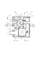
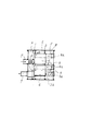
まず、排気マフラ装置本体10を説明する。すなわち、図2に示すように、排気マフラ装置本体10の材料は、耐腐食を考慮して、例えばステンレス材が用いられ、外観形状を箱形に形成された筒状の外殻11両端開口部を上流側エンドプレート(以下「左エンドプレート」という)12と下流側エンドプレート(以下「右エンドプレート」という)13とにより閉塞して形成される。左エンドプレート12は、内板12aと外板12bとの間に吸音、消音効果に有効な素材であるグラスウール12cが充填され、同様に、右エンドプレート13にもその内板13aと外板13bとの間にグラスウール13cが充填されている。また、左右両エンドプレート12,13の内板12a,13aとしては、例えば、ピッチ間隔が3.5で、内径φ2の凹形状のパンチング加工が施され、上記グラスウール12c、13cによる消音効果が発揮できるようにしている。
First, the exhaust
排気マフラ本体10内部には、図1に対して右方から所定間隔を存して、内部室を仕切るように第1隔壁14と第2隔壁15が設けられ、右方から順に、右エンドプレート13と第1隔壁14とで仕切られた膨脹室としての第1室Aと、第1隔壁14と第2隔壁15とで仕切られた共鳴室としての第2室Bと、第2隔壁15と左エンドプレート12とで仕切られた膨脹室としての第3室Cが形成される。
A
また、排気マフラ本体10内部の第1隔壁14と第2隔壁15に跨って排気浄化手段17が設けられ、下流側に向かって末拡がり状に横断面積が拡大するラッパ状管18を介して左エンドプレート12に貫通支持した排気入口管16に接続(溶接)される。
Further, exhaust purification means 17 is provided across the
上記排気浄化手段17は、例えば、触媒モノリスの態様の浄化手段であり、多孔質のハニカム構造を有し、これに酸化触媒、あるいは還元触媒等種々の触媒から適宜選択された触媒を担持させることで形成されるものであり、排気ガス中に含まれる有害物質の酸化、あるいは還元反応を促進するようになっている。 The exhaust purification means 17 is, for example, a purification means in the form of a catalyst monolith, which has a porous honeycomb structure, and carries a catalyst appropriately selected from various catalysts such as an oxidation catalyst or a reduction catalyst. It promotes the oxidation or reduction reaction of harmful substances contained in the exhaust gas.
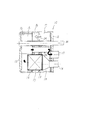
一方、排気浄化手段17の上方には、排気マフラ装置本体10の長手軸線方向に沿って、第1の連通管21(図2参照)と、この第1の連通管10と略平行に配置した第2の連通管22(図3参照)とが、それぞれ第2室Bを貫通するようにして第1隔壁14と第2隔壁15とに支持(溶接)され、第1室Aと第3室Cとが連通するようにしている。すなわち、第1の連通管14は、第1室A側では開口し、第3室Cではその管端が閉塞され、周壁に形成した多数のパンチ孔21aを介して第3室Cに連通している。また、第2の連通管22は、パンチ孔を有しない管であり、図3に示すように、第3室C側の管端は限りなく左エンドプレート12の内板12aに近接した位置で開口し、ここから第3室C内に流出した排気ガスがすぐさま左エンドプレート12に設けた排気出口管19に流れ込むようにしている。なお、排気出口管19は排気管100(図1参照)に接続し、サブマフラ装置110に連通している。
On the other hand, above the exhaust purification means 17, a first communication pipe 21 (see FIG. 2) and the
他方、第1隔壁14と第2隔壁15とに、上記第1、第2の両連通管21,22に略平行に配置した第3の連通管23が支持(溶接)されている。この第3の連通管23は、図2に示されるように、第2隔壁15から左方、すなわち、第3室C側に所定長さの寸法で突出する枝管部23aと、枝管部23aから中央の第2室B内へ突出し、その管端を閉塞させた延長管部23bとからなり、その延長管部23b周壁には第2室Bに通じる多数のパンチ孔23cが穿たれ、これにより第3の連通管23を介して第3室Cから第2室Bに排気ガスの音の流れが流入(伝播)するようにしている。また、第2隔壁15の上方には、各連通管21〜23の外径に略等しい内径の穴部24が設けられ、第2室B内から第3室Cへ排気ガスの音が伝播するようにしている。
こうして、第2室Bと、枝管部23aと、穴部24とによりヘルムホルツ型共鳴器の原理を利用した共鳴手段が形成されることとなる。
On the other hand, a
Thus, the second chamber B, the branch pipe portion 23a, and the
また、第1室Aの略上半分の内周壁面には、図5に示すように、多数のパンチ孔を形成したパンチングメタル25が設けられ、その裏側に、上記エンドプレート14,15の場合と同様に適宜の吸音材であるグラスウールが充填された構造にしている。
Further, as shown in FIG. 5, a punching
なお、図2,図3における符号30は、排気マフラ本体10を車体(例えばトラック)の適宜箇所(フレーム)に装着するために使用されるサポート部材を示し、排気マフラ本体10の長手軸線方向に沿って貫通するように取り付けられている。また、31は、装着された排気マフラ本体10が揺動するのを防止するため、左エンドプレート12に設けられた回り止め部材を示す。
2 and 3 indicate a support member used for mounting the exhaust muffler
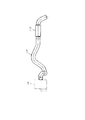
次に、サブマフラ装置110を説明する。すなわち、サブマフラ装置110は、排気マフラ装置本体10に対するアフターマフラであり、排気マフラ装置本体10や排気管100と同様にステンレス材で形成され、図6によく示されるように、排気マフラ装置本体10の下流側の排気管100のテールパイプ近傍に設けられている。サブマフラ装置110は排気マフラ装置本体10から良好な消音効果が得られる位置となるようにマッチングさせて配置している。
Next, the
サブマフラ装置110は、横断面が円形をなす内筒110aと外筒110bとで形成され、内外両筒110a,110bの間に、膨脹室111が設けられる。内筒110aは、図6(b)に示すように、直径が略4mmの多数のパンチ孔110cが穿たれたパンチングメタル(ステンレス材)で、かつ、膨脹室111に密度が略120g/cm3のグラスウールといった吸音材がハッチングで図示したように充填されている。
The
次に、本実施形態の作用を主として図2、図3を参照して説明する。なお、図2,図3中における黒塗り矢印は排気ガスの流れ方向を、白抜き矢印は排気音が伝播する方向を示す。すなわち、エンジン(図示しない)から排気入口管16に導かれてきた排気ガスは、ラッパ状管18から排気浄化手段17の内部を流れ、排気ガスに含まれる有害物質が浄化された後、第1室Aに膨脹拡散して流れ込むので、排気ガスの圧力変動が低減されて騒音が低減される。次いで、第1室A内の排気ガスは、第2の連通管22(図3参照)に絞り込まれて内部に送り込まれるが、この排気ガスの絞り込みの過程により排気ガスの排気音が消音される。第2の連通管22の送り込まれた排気ガスは、その出口から第3室C内に膨脹拡散して流出するので、ここでも排気ガスが有する圧力変動を低減して減衰される。その後、排気ガスは第3室Cからすぐさま排気出口管19に入ってサブマフラ装置110へ流れていく。同時に、第2の連通管22は気柱共鳴の機能を有するため、気柱共鳴に等しい排気音の振動成分が干渉によって減衰されるため、第2の連通管22が有する気柱共鳴機能によっても消音効果が得られる。
Next, the operation of the present embodiment will be described mainly with reference to FIGS. 2 and 3, black arrows indicate the exhaust gas flow direction, and white arrows indicate the direction in which the exhaust sound propagates. That is, the exhaust gas guided from the engine (not shown) to the
一方、第1室Aの排気ガスは、第1の連通管21にも絞り込まれて流れ込むので、この絞り込みの過程でも排気ガスの排気音が消される。そして、パンチ孔21aから第3室Cに排気ガスが膨脹拡散する過程で、排気ガスの圧力変動は低減されるので消音され、その後、第3室Cの排気ガスは、排気出口管19から排出され、サブマフラ装置110へ流れていく。
On the other hand, the exhaust gas in the first chamber A is squeezed into the
他方、第3室C内における排気ガスの有する排気音の流れ(伝播)に着目すると、排気音の流れは枝管部23aから延長管部23bのパンチ孔23cを経由して第2室Bに伝播し、第2室B内で或る特定周波数成分に等しい振動成分が干渉によって減衰され、また、第2隔壁15に形成した穴部24(図3参照)を通過して音が第3室Cへ伝播するときにも特定周波数成分に等しい振動成分が干渉によって減衰されていくので、これらにより排気騒音が減衰して消音効果を発揮する。
また、延長管部23bのパンチ孔23cから第2室Bに排気ガスが膨脹拡散して入るので、排気ガスの圧力変動はここでも低減されるので、騒音低減に効果を発揮する。
On the other hand, focusing on the flow (propagation) of the exhaust sound of the exhaust gas in the third chamber C, the flow of the exhaust sound flows from the branch pipe portion 23a to the second chamber B via the
In addition, since the exhaust gas expands and diffuses into the second chamber B from the
また、排気マフラ装置本体10から排出された排気ガスは、途中の排気管100を流動してサブマフラ装置110内へ供給されていくが、排気ガスがサブマフラ装置110を流量するとき、排気ガスはパンチ孔110cを通過して膨脹室111に流入して膨脹するので、これによって排気騒音が低減され、またグラスウールによる吸音効果によっても排気騒音が減音されることとなる。
Further, the exhaust gas discharged from the exhaust
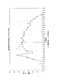
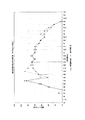
本出願人は、上記実施形態に係る排気マフラ装置本体10およびサブマフラ装置110を用いて、最も多く使用されるエンジン回転域(経済走行域)、例えばディーゼルエンジンを1850rpmで回転させた場合について実験を行った。その結果、図7および図8に示すような排気音周波数分析のグラフを得ることができた。すなわち、図7は上記実施形態に係る排気マフラ装置本体10と、そうでない従来構造品のマフラ装置とについて比較試験を行って得たグラフ、また、図8は上記実施形態に係るサブマフラ装置110を装着した場合と、装着しない場合とを比較試験したグラフを示す。
The present applicant conducted an experiment using the exhaust
図7からわかるように、本実施形態に係る排気マフラ装置本体10を装着した場合の方が、従来構造品のマフラ装置を搭載した場合よりも、200〜500Hzの周波数帯域で排気騒音レベルが著しく低減されており、また、図8には、サブマフラ装置110を搭載した場合には、搭載しない場合に対して160Hz以降の全周波数帯域で騒音レベルが低減している結果を得ることができた。これら実験結果からもわかるように、本実施形態によれば、エンジンから排出される排気ガスの騒音は、上記排気マフラ装置本体10を用いることで大幅に低減し、消音することができる効果があり、さらに、上記サブマフラ装置110を排気マフラ装置本体10の下流に搭載することで一層排気ガスの騒音を低減するのに有利となる効果を有する。
As can be seen from FIG. 7, the exhaust noise level in the frequency band of 200 to 500 Hz is significantly higher when the exhaust
上記したように、本実施形態によれば、排気マフラ装置本体10内に収納した排気浄化手段17による排気浄化効率を向上できるだけでなく、排気騒音の低減や消音効果に優れた、コンパクトな排気マフラ装置を得ることができ、また、下流側にサブマフラ装置110をアフターマフラとして搭載することで、排気系システム全体としても一層の排気騒音、消音効果を高めることができる効果を有する。
As described above, according to the present embodiment, not only the exhaust purification efficiency by the exhaust purification means 17 housed in the exhaust
以上、本発明の実施の形態を図面より詳述してきたが、具体的な構成はこの実施の形態に限られるものではなく、本発明の要旨を逸脱しない範囲の設計変形等があっても本発明に含まれる。
例えば、上記実施形態では、排気浄化手段17として触媒モノリスについて説明したが、この代わりに、ディーゼルエンジンの排気系のパティキュレートフィルターについて適用することもできる。この場合、パティキュレートフィルターは、例えば、多数のハニカム状に配置された多孔質の炭化珪素やコージェライトの焼結体でなる排気ガス通路を有する、いわゆるウォールフローハニカムフィルターといった浄化手段を利用する形態でもよい。
The embodiment of the present invention has been described in detail above with reference to the drawings. However, the specific configuration is not limited to this embodiment, and even if there is a design modification or the like without departing from the gist of the present invention. Included in the invention.
For example, in the above-described embodiment, the catalyst monolith has been described as the
また、上記実施形態では、パンチ孔23cを備えた延長管部23bを第3の連通管23として形成し、第2室Bと、枝管部23aと、穴部24とによりヘルムホルツ型共鳴器の原理を利用した共鳴手段としたが、このような連通管23の形態によることなく、すなわち延長管部23bを設けることなく、単に枝管部23aの長さや、第2室Bの容積を適宜に設定するようにしてもよい。これにより、その排気マフラ装置に合った排気音の減衰、消音特性が得られるようにチューニングするのは勿論である。
Moreover, in the said embodiment, the extension pipe part 23b provided with the
10 排気マフラ装置本体
11 外殻
12 左エンドプレート
13 右エンドプレート
14 第1隔壁
15 第2隔壁
16 排気入口管
17 排気浄化手段
18 ラッパ状管
19 排気出口管
21 第1の連通管
21a パンチ孔
22 第2の連通管
23 第3の連通管
23a 枝管部
23b 延長管部
23c パンチ孔
24 穴部
100 排気管
110 サブマフラ装置
110c パンチ孔
111 膨脹室
A 第1室
B 第2室
C 第3室
DESCRIPTION OF
Claims (5)
Priority Applications (1)
| Application Number | Priority Date | Filing Date | Title |
|---|---|---|---|
| JP2004015312A JP2005207331A (en) | 2004-01-23 | 2004-01-23 | Exhaust muffler apparatus |
Applications Claiming Priority (1)
| Application Number | Priority Date | Filing Date | Title |
|---|---|---|---|
| JP2004015312A JP2005207331A (en) | 2004-01-23 | 2004-01-23 | Exhaust muffler apparatus |
Publications (1)
| Publication Number | Publication Date |
|---|---|
| JP2005207331A true JP2005207331A (en) | 2005-08-04 |
Family
ID=34900820
Family Applications (1)
| Application Number | Title | Priority Date | Filing Date |
|---|---|---|---|
| JP2004015312A Pending JP2005207331A (en) | 2004-01-23 | 2004-01-23 | Exhaust muffler apparatus |
Country Status (1)
| Country | Link |
|---|---|
| JP (1) | JP2005207331A (en) |
Cited By (3)
| Publication number | Priority date | Publication date | Assignee | Title |
|---|---|---|---|---|
| WO2010128570A1 (en) * | 2009-05-08 | 2010-11-11 | パワー ドラゴン グローバル リミティド | Exhaust gas purifying device |
| CN110469384A (en) * | 2019-09-10 | 2019-11-19 | 重庆宗申通用动力机械有限公司 | A silent engine muffler |
| WO2020031434A1 (en) * | 2018-08-10 | 2020-02-13 | 日本碍子株式会社 | Honeycomb structural body, exhaust gas purification device, exhaust system, and method for producing honeycomb structural body |
-
2004
- 2004-01-23 JP JP2004015312A patent/JP2005207331A/en active Pending
Cited By (6)
| Publication number | Priority date | Publication date | Assignee | Title |
|---|---|---|---|---|
| WO2010128570A1 (en) * | 2009-05-08 | 2010-11-11 | パワー ドラゴン グローバル リミティド | Exhaust gas purifying device |
| WO2020031434A1 (en) * | 2018-08-10 | 2020-02-13 | 日本碍子株式会社 | Honeycomb structural body, exhaust gas purification device, exhaust system, and method for producing honeycomb structural body |
| CN112512993A (en) * | 2018-08-10 | 2021-03-16 | 日本碍子株式会社 | Honeycomb structure, exhaust gas purifying apparatus, exhaust system, and method for manufacturing honeycomb structure |
| JPWO2020031434A1 (en) * | 2018-08-10 | 2021-09-24 | 日本碍子株式会社 | Honeycomb structure, exhaust gas purification device, exhaust system and manufacturing method of honeycomb structure |
| US11614011B2 (en) | 2018-08-10 | 2023-03-28 | Ngk Insulators, Ltd. | Pillar shaped honeycomb structure, exhaust gas purifying device, exhaust system, and method for producing honeycomb structure |
| CN110469384A (en) * | 2019-09-10 | 2019-11-19 | 重庆宗申通用动力机械有限公司 | A silent engine muffler |
Similar Documents
| Publication | Publication Date | Title |
|---|---|---|
| US7549511B2 (en) | Exhaust sound and emission control systems | |
| US5426269A (en) | Muffler with catalytic converter arrangement; and method | |
| US5355973A (en) | Muffler with catalytic converter arrangement; and method | |
| JP3231852B2 (en) | Silencer incorporated in catalytic converter of internal combustion engine | |
| KR101823215B1 (en) | Vehicle exhaust system with resonance damping | |
| JP5532043B2 (en) | Vehicle silencer | |
| JPH04175418A (en) | Catalyst incorporating silencer | |
| JP2009062922A (en) | Resonance device and exhaust system for internal combustion engine | |
| US3994364A (en) | Mufflers | |
| US3515242A (en) | Exhaust silencer for internal combustion engines | |
| JP2004519575A (en) | Device for damping resonance in conduit | |
| JP2002070524A (en) | Catalytic muffler | |
| JP2006207378A (en) | Noise reduction device for exhaust system and exhaust system having the same | |
| JP2524580B2 (en) | Exhaust silencer | |
| US3613829A (en) | Double triflow muffler | |
| JP2006283625A (en) | High frequency sound reduction silencer | |
| JP3445560B2 (en) | Muffler | |
| JP3900291B2 (en) | Exhaust muffler | |
| JP2729188B2 (en) | Car silencer | |
| JPH08319817A (en) | Muffler for vehicle | |
| JP2005069191A (en) | Exhaust device | |
| JP2000248921A (en) | Purifying silencer | |
| RU2241126C1 (en) | Internal combustion engine muffler | |
| RU2333370C1 (en) | Silencer | |
| WO2010128570A1 (en) | Exhaust gas purifying device |
Legal Events
| Date | Code | Title | Description |
|---|---|---|---|
| A977 | Report on retrieval |
Free format text: JAPANESE INTERMEDIATE CODE: A971007 Effective date: 20060720 |
|
| A131 | Notification of reasons for refusal |
Free format text: JAPANESE INTERMEDIATE CODE: A131 Effective date: 20060815 |
|
| A521 | Written amendment |
Free format text: JAPANESE INTERMEDIATE CODE: A523 Effective date: 20060925 |
|
| A02 | Decision of refusal |
Free format text: JAPANESE INTERMEDIATE CODE: A02 Effective date: 20070116 |