JP2005222013A - Manufacturing method of polarizing plate, polarizing plate, optical film, and image display device - Google Patents
Manufacturing method of polarizing plate, polarizing plate, optical film, and image display device Download PDFInfo
- Publication number
- JP2005222013A JP2005222013A JP2004208584A JP2004208584A JP2005222013A JP 2005222013 A JP2005222013 A JP 2005222013A JP 2004208584 A JP2004208584 A JP 2004208584A JP 2004208584 A JP2004208584 A JP 2004208584A JP 2005222013 A JP2005222013 A JP 2005222013A
- Authority
- JP
- Japan
- Prior art keywords
- polarizing plate
- transparent protective
- polarizer
- protective film
- film
- Prior art date
- Legal status (The legal status is an assumption and is not a legal conclusion. Google has not performed a legal analysis and makes no representation as to the accuracy of the status listed.)
- Pending
Links
Images
Classifications
-
- B—PERFORMING OPERATIONS; TRANSPORTING
- B32—LAYERED PRODUCTS
- B32B—LAYERED PRODUCTS, i.e. PRODUCTS BUILT-UP OF STRATA OF FLAT OR NON-FLAT, e.g. CELLULAR OR HONEYCOMB, FORM
- B32B27/00—Layered products comprising a layer of synthetic resin
- B32B27/06—Layered products comprising a layer of synthetic resin as the main or only constituent of a layer, which is next to another layer of the same or of a different material
- B32B27/08—Layered products comprising a layer of synthetic resin as the main or only constituent of a layer, which is next to another layer of the same or of a different material of synthetic resin
-
- G—PHYSICS
- G02—OPTICS
- G02F—OPTICAL DEVICES OR ARRANGEMENTS FOR THE CONTROL OF LIGHT BY MODIFICATION OF THE OPTICAL PROPERTIES OF THE MEDIA OF THE ELEMENTS INVOLVED THEREIN; NON-LINEAR OPTICS; FREQUENCY-CHANGING OF LIGHT; OPTICAL LOGIC ELEMENTS; OPTICAL ANALOGUE/DIGITAL CONVERTERS
- G02F1/00—Devices or arrangements for the control of the intensity, colour, phase, polarisation or direction of light arriving from an independent light source, e.g. switching, gating or modulating; Non-linear optics
- G02F1/01—Devices or arrangements for the control of the intensity, colour, phase, polarisation or direction of light arriving from an independent light source, e.g. switching, gating or modulating; Non-linear optics for the control of the intensity, phase, polarisation or colour
- G02F1/13—Devices or arrangements for the control of the intensity, colour, phase, polarisation or direction of light arriving from an independent light source, e.g. switching, gating or modulating; Non-linear optics for the control of the intensity, phase, polarisation or colour based on liquid crystals, e.g. single liquid crystal display cells
- G02F1/133—Constructional arrangements; Operation of liquid crystal cells; Circuit arrangements
- G02F1/1333—Constructional arrangements; Manufacturing methods
- G02F1/1335—Structural association of cells with optical devices, e.g. polarisers or reflectors
-
- B—PERFORMING OPERATIONS; TRANSPORTING
- B05—SPRAYING OR ATOMISING IN GENERAL; APPLYING FLUENT MATERIALS TO SURFACES, IN GENERAL
- B05D—PROCESSES FOR APPLYING FLUENT MATERIALS TO SURFACES, IN GENERAL
- B05D3/00—Pretreatment of surfaces to which liquids or other fluent materials are to be applied; After-treatment of applied coatings, e.g. intermediate treating of an applied coating preparatory to subsequent applications of liquids or other fluent materials
- B05D3/06—Pretreatment of surfaces to which liquids or other fluent materials are to be applied; After-treatment of applied coatings, e.g. intermediate treating of an applied coating preparatory to subsequent applications of liquids or other fluent materials by exposure to radiation
-
- B—PERFORMING OPERATIONS; TRANSPORTING
- B32—LAYERED PRODUCTS
- B32B—LAYERED PRODUCTS, i.e. PRODUCTS BUILT-UP OF STRATA OF FLAT OR NON-FLAT, e.g. CELLULAR OR HONEYCOMB, FORM
- B32B27/00—Layered products comprising a layer of synthetic resin
- B32B27/30—Layered products comprising a layer of synthetic resin comprising vinyl (co)polymers; comprising acrylic (co)polymers
- B32B27/306—Layered products comprising a layer of synthetic resin comprising vinyl (co)polymers; comprising acrylic (co)polymers comprising vinyl acetate or vinyl alcohol (co)polymers
-
- B—PERFORMING OPERATIONS; TRANSPORTING
- B32—LAYERED PRODUCTS
- B32B—LAYERED PRODUCTS, i.e. PRODUCTS BUILT-UP OF STRATA OF FLAT OR NON-FLAT, e.g. CELLULAR OR HONEYCOMB, FORM
- B32B27/00—Layered products comprising a layer of synthetic resin
- B32B27/32—Layered products comprising a layer of synthetic resin comprising polyolefins
-
- B—PERFORMING OPERATIONS; TRANSPORTING
- B32—LAYERED PRODUCTS
- B32B—LAYERED PRODUCTS, i.e. PRODUCTS BUILT-UP OF STRATA OF FLAT OR NON-FLAT, e.g. CELLULAR OR HONEYCOMB, FORM
- B32B7/00—Layered products characterised by the relation between layers; Layered products characterised by the relative orientation of features between layers, or by the relative values of a measurable parameter between layers, i.e. products comprising layers having different physical, chemical or physicochemical properties; Layered products characterised by the interconnection of layers
- B32B7/04—Interconnection of layers
- B32B7/12—Interconnection of layers using interposed adhesives or interposed materials with bonding properties
-
- G—PHYSICS
- G02—OPTICS
- G02B—OPTICAL ELEMENTS, SYSTEMS OR APPARATUS
- G02B5/00—Optical elements other than lenses
- G02B5/30—Polarising elements
-
- G—PHYSICS
- G02—OPTICS
- G02B—OPTICAL ELEMENTS, SYSTEMS OR APPARATUS
- G02B5/00—Optical elements other than lenses
- G02B5/30—Polarising elements
- G02B5/3025—Polarisers, i.e. arrangements capable of producing a definite output polarisation state from an unpolarised input state
- G02B5/3033—Polarisers, i.e. arrangements capable of producing a definite output polarisation state from an unpolarised input state in the form of a thin sheet or foil, e.g. Polaroid
- G02B5/3041—Polarisers, i.e. arrangements capable of producing a definite output polarisation state from an unpolarised input state in the form of a thin sheet or foil, e.g. Polaroid comprising multiple thin layers, e.g. multilayer stacks
- G02B5/305—Polarisers, i.e. arrangements capable of producing a definite output polarisation state from an unpolarised input state in the form of a thin sheet or foil, e.g. Polaroid comprising multiple thin layers, e.g. multilayer stacks including organic materials, e.g. polymeric layers
-
- B—PERFORMING OPERATIONS; TRANSPORTING
- B32—LAYERED PRODUCTS
- B32B—LAYERED PRODUCTS, i.e. PRODUCTS BUILT-UP OF STRATA OF FLAT OR NON-FLAT, e.g. CELLULAR OR HONEYCOMB, FORM
- B32B2551/00—Optical elements
-
- Y—GENERAL TAGGING OF NEW TECHNOLOGICAL DEVELOPMENTS; GENERAL TAGGING OF CROSS-SECTIONAL TECHNOLOGIES SPANNING OVER SEVERAL SECTIONS OF THE IPC; TECHNICAL SUBJECTS COVERED BY FORMER USPC CROSS-REFERENCE ART COLLECTIONS [XRACs] AND DIGESTS
- Y10—TECHNICAL SUBJECTS COVERED BY FORMER USPC
- Y10T—TECHNICAL SUBJECTS COVERED BY FORMER US CLASSIFICATION
- Y10T428/00—Stock material or miscellaneous articles
- Y10T428/31504—Composite [nonstructural laminate]
- Y10T428/31855—Of addition polymer from unsaturated monomers
- Y10T428/31859—Next to an aldehyde or ketone condensation product
-
- Y—GENERAL TAGGING OF NEW TECHNOLOGICAL DEVELOPMENTS; GENERAL TAGGING OF CROSS-SECTIONAL TECHNOLOGIES SPANNING OVER SEVERAL SECTIONS OF THE IPC; TECHNICAL SUBJECTS COVERED BY FORMER USPC CROSS-REFERENCE ART COLLECTIONS [XRACs] AND DIGESTS
- Y10—TECHNICAL SUBJECTS COVERED BY FORMER USPC
- Y10T—TECHNICAL SUBJECTS COVERED BY FORMER US CLASSIFICATION
- Y10T428/00—Stock material or miscellaneous articles
- Y10T428/31504—Composite [nonstructural laminate]
- Y10T428/31855—Of addition polymer from unsaturated monomers
- Y10T428/31909—Next to second addition polymer from unsaturated monomers
Landscapes
- Physics & Mathematics (AREA)
- General Physics & Mathematics (AREA)
- Optics & Photonics (AREA)
- Nonlinear Science (AREA)
- Engineering & Computer Science (AREA)
- Plasma & Fusion (AREA)
- Mathematical Physics (AREA)
- Chemical & Material Sciences (AREA)
- Crystallography & Structural Chemistry (AREA)
- Polarising Elements (AREA)
- Liquid Crystal (AREA)
Abstract
【課題】 ポリビニルアルコール偏光子の少なくとも一方の面に、環状オレフィン系樹脂を用いた透明保護フィルムを設けた偏光板であって、偏光子と透明保護フィルムとの接着力がよく、均一な偏光特性を有するものを製造する方法を提供すること。
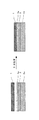
【解決手段】 偏光子(1)の少なくとも一方の面に透明保護フィルム(2)が設けられている偏光板の製造方法であって、前記少なくとも一方の透明保護フィルム(2a)は、環状オレフィン系樹脂を主成分としており、かつ、透明保護フィルム(2a)の偏光子(1)に貼り合わせる面には、少なくとも1層以上の樹脂層(3)およびポリビニルアルコール系接着剤層(4a)が順次に積層されており、前記透明保護フィルム(2a)のポリビニルアルコール系接着剤層(4a)と偏光子(1)とを貼り合わせる際に、貼り合わせ面に水性液(5)を存在させることを特徴とする偏光板の製造方法。
【選択図】 図1
PROBLEM TO BE SOLVED: To provide a polarizing plate in which a transparent protective film using a cyclic olefin-based resin is provided on at least one surface of a polyvinyl alcohol polarizer, and the adhesive force between the polarizer and the transparent protective film is good and uniform polarizing characteristics To provide a method of manufacturing a product having
SOLUTION: A method for producing a polarizing plate in which a transparent protective film (2) is provided on at least one surface of a polarizer (1), wherein the at least one transparent protective film (2a) is a cyclic olefin type. At least one resin layer (3) and a polyvinyl alcohol-based adhesive layer (4a) are sequentially formed on the surface of the transparent protective film (2a) to be bonded to the polarizer (1). When the polyvinyl alcohol adhesive layer (4a) of the transparent protective film (2a) and the polarizer (1) are bonded together, the aqueous liquid (5) is present on the bonding surface. A method for producing a polarizing plate.
[Selection] Figure 1
Description
本発明は、偏光板の製造方法に関する。また本発明は当該製造方法により得られた偏光板に関する。当該偏光板はこれ単独で、またはこれを積層した光学フィルムとして液晶表示装置(以下、LCDと略す)、エレクトロミネッセンス表示装置(以下、ELDと略す)等のフラットパネルディスプレー、PDP等の画像表示装置を形成しうる。 The present invention relates to a method for producing a polarizing plate. Moreover, this invention relates to the polarizing plate obtained by the said manufacturing method. The polarizing plate is an optical film obtained by laminating the polarizing plate alone, or a flat panel display such as a liquid crystal display device (hereinafter abbreviated as LCD) or an electroluminescence display device (hereinafter abbreviated as ELD), or an image such as a PDP. A display device can be formed.
従来より、LCDに用いられる偏光板には偏光子の両面に透明保護フィルムを接着剤で貼り合わせたものが一般に用いられている。偏光子としてはポリビニルアルコールにヨウ素または二色性染料を吸着させ延伸することにより配向させたポリビニルアルコール系偏光子が用いられ、透明保護フィルムとしてはトリアセチルセルロースを用いたものが一般的である。 2. Description of the Related Art Conventionally, a polarizing plate used for an LCD generally has a transparent protective film bonded to both sides of a polarizer with an adhesive. As the polarizer, a polyvinyl alcohol polarizer oriented by adsorbing iodine or dichroic dye on polyvinyl alcohol and stretching is used, and a transparent protective film using triacetyl cellulose is generally used.
しかしながら、トリアセチルセルロースは耐湿熱性が十分でない。そのため、トリアセチルセルロースフィルムを透明保護フィルムとして用いた偏光板を高温下または高湿下において使用すると偏光性能の低下、具体的には偏光度や色相が低下するという欠点があった。また、トリアセチルセルロースフィルムは斜め方向の位相差が大きい。そのため、近年、LCDの大型化が進むにつれて、透明保護フィルムとしてトリアセチルセルロースフィルムを用いた場合には、視野角特性に及ぼす影響が大きい。 However, triacetyl cellulose does not have sufficient heat and humidity resistance. Therefore, when a polarizing plate using a triacetyl cellulose film as a transparent protective film is used at high temperature or high humidity, there is a drawback that the polarization performance is lowered, specifically, the degree of polarization and the hue are lowered. Further, the triacetyl cellulose film has a large retardation in the oblique direction. Therefore, in recent years, as the size of LCDs increases, the use of a triacetyl cellulose film as a transparent protective film has a large effect on viewing angle characteristics.
上記の問題を解決するために、透明保護フィルムとしてトリアセチルセルロースの代わりに環状オレフィン系樹脂を用いることが提案されている。環状オレフィン系樹脂は透湿性が低く、また斜め方向の位相差がほとんどない。しかし、環状オレフィン系樹脂とポリビニルアルコール系偏光子との接着に従来のトリアセチルセルロースとポリビニルアルコール系偏光子との接着に用いるポリビニルアルコール系接着剤を使用すると接着性に乏しい。 In order to solve the above problems, it has been proposed to use a cyclic olefin resin as a transparent protective film instead of triacetyl cellulose. Cyclic olefin-based resins have low moisture permeability and have almost no phase difference in the oblique direction. However, when a conventional polyvinyl alcohol-based adhesive used for bonding between a triacetyl cellulose and a polyvinyl alcohol-based polarizer is used for bonding the cyclic olefin-based resin and the polyvinyl alcohol-based polarizer, the adhesion is poor.
そこで、環状オレフィン系樹脂を用いた透明保護フィルムとポリビニルアルコール系偏光子とを接着する方法として、例えば、アクリル系粘着剤層を介して接着する方法が提案されている(特許文献1)。しかしながら、この方法は加熱圧着が必要であり、加熱時間も長いためポリビニルアルコール偏光子が変色してしまい、偏光度が著しく低下してしまうという問題点があった。さらには、長時間の加熱が必要なため生産効率が低く、フィルムが変形してしまうという問題がある。 Thus, as a method for bonding a transparent protective film using a cyclic olefin resin and a polyvinyl alcohol polarizer, for example, a method of bonding via an acrylic pressure-sensitive adhesive layer has been proposed (Patent Document 1). However, this method has a problem that thermocompression bonding is required and the heating time is long, so that the polyvinyl alcohol polarizer is discolored and the degree of polarization is significantly reduced. Furthermore, since heating for a long time is required, there is a problem that the production efficiency is low and the film is deformed.
また、熱可塑性飽和ノルボルネン系樹脂フィルムにポリウレタン樹脂層及びポリビニルアルコール層を積層した透明保護フィルムとポリビニルアルコール系偏光子とを、ポリビニルアルコール系接着剤により接着して偏光板を製造する方法が提案されている(特許文献2)。しかしながら、この方法は、透明保護フィルムとポリビニルアルコール偏光子を接着させた際に、浮きやスジなどが発生し、外観が安定せず、生産性に乏しいという問題点があった。かかるスジ状外観欠点は、偏光板の高度な要求特性の中で、特に光学的均一性に影響を与える。そのため、LCDの高精細化、高機能化にともない画面の均一性、品位の向上には対応できなかった。スジ状外観欠点とは、透明保護フィルムを貼り合わせて得られた偏光板の吸収軸方向に対して、平行にストライプ状のスジが反射の状態で見えることをいう。スジの特徴としては、1〜2mmピッチでレコード盤に刻まれている溝のような形状である。
本発明は、ポリビニルアルコール偏光子の少なくとも一方の面に、環状オレフィン系樹脂を用いた透明保護フィルムを設けた偏光板であって、偏光子と透明保護フィルムとの接着力がよく、均一な偏光特性を有するものを製造する方法を提供することを目的とする。 The present invention is a polarizing plate in which a transparent protective film using a cyclic olefin-based resin is provided on at least one surface of a polyvinyl alcohol polarizer, which has good adhesion between the polarizer and the transparent protective film, and has uniform polarization. It aims at providing the method of manufacturing what has a characteristic.
また本発明は当該製造方法により得られた偏光板を提供することを目的とする。また当該偏光板を積層した光学フィルム、さらには当該偏光板、光学フィルムを用いたLCD、ELD等の画像表示装置を提供することを目的とする。 Another object of the present invention is to provide a polarizing plate obtained by the production method. Moreover, it aims at providing image display apparatuses, such as an optical film which laminated | stacked the said polarizing plate, and also the LCD and ELD which used the said polarizing plate and the optical film.
本発明者らは前記課題を解決すべく鋭意検討を重ねた結果、以下に示す偏光板の製造方法により前記目的に達成できることを見出し、本発明を完成するに至った。すなわち本発明は以下の通りである。 As a result of intensive studies to solve the above-mentioned problems, the present inventors have found that the object can be achieved by the following method for producing a polarizing plate, and have completed the present invention. That is, the present invention is as follows.
1.偏光子の少なくとも一方の面に透明保護フィルムが設けられている偏光板の製造方法であって、
前記少なくとも一方の透明保護フィルムは、環状オレフィン系樹脂を主成分としており、かつ、
透明保護フィルムの偏光子に貼り合わせる面には、少なくとも1層以上の樹脂層およびポリビニルアルコール系接着剤層が順次に積層されており、
前記透明保護フィルムのポリビニルアルコール系接着剤層と偏光子とを貼り合わせる際に、貼り合わせ面に水性液を存在させることを特徴とする偏光板の製造方法。
1. A method for producing a polarizing plate in which a transparent protective film is provided on at least one surface of a polarizer,
The at least one transparent protective film is mainly composed of a cyclic olefin resin, and
On the surface to be bonded to the polarizer of the transparent protective film, at least one resin layer and a polyvinyl alcohol adhesive layer are sequentially laminated,
A method for producing a polarizing plate, wherein an aqueous liquid is present on a bonding surface when a polyvinyl alcohol adhesive layer of a transparent protective film and a polarizer are bonded together.
2.水性液が、水であることを特徴とする上記1記載の偏光板の製造方法。 2. 2. The method for producing a polarizing plate as described in 1 above, wherein the aqueous liquid is water.
3.水性液が、架橋剤を溶解する水溶液であることを特徴とする上記1または2記載の偏光板の製造方法。 3. 3. The method for producing a polarizing plate according to 1 or 2, wherein the aqueous liquid is an aqueous solution in which a crosslinking agent is dissolved.
4.架橋剤が、メラミン系架橋剤であることを特徴とする上記3記載の偏光板の製造方法。 4). 4. The method for producing a polarizing plate according to 3 above, wherein the crosslinking agent is a melamine-based crosslinking agent.
5.メラミン系架橋剤が、メチロールメラミンであることを特徴とする上記4記載の偏光板の製造方法。 5). 5. The method for producing a polarizing plate according to 4 above, wherein the melamine-based crosslinking agent is methylol melamine.
6.偏光子がポリビニルアルコール系偏光子であることを特徴とする上記1〜5のいずれかに記載の偏光板の製造方法。 6). 6. The method for producing a polarizing plate according to any one of the above 1 to 5, wherein the polarizer is a polyvinyl alcohol polarizer.
7.上記1〜6のいずれかに記載の製造方法により得られた偏光板。 7). The polarizing plate obtained by the manufacturing method in any one of said 1-6.
8.上記7記載の偏光板が、少なくとも1枚積層されていることを特徴とする光学フィルム。 8). 8. An optical film, wherein at least one polarizing plate according to 7 is laminated.
9.上記7記載の偏光板または上記8記載の光学フィルムが用いられていることを特徴とする画像表示装置。 9. 8. An image display device comprising the polarizing plate according to 7 or the optical film according to 8 above.
上記本発明の偏光板の製造方法では、環状オレフィン系樹脂を主成分とする透明保護フィルムと偏光子とを貼り合わせている。また当該透明保護フィルムは、偏光子に貼り合わせる面に、予め樹脂層を介してポリビニルアルコール系接着層が積層されたものが用いられおり、偏光子と透明保護フィルムとを接着状態よく貼り合わせることができる。 In the manufacturing method of the polarizing plate of the said invention, the transparent protective film which has cyclic olefin resin as a main component, and a polarizer are bonded together. In addition, the transparent protective film in which a polyvinyl alcohol-based adhesive layer is previously laminated on the surface to be bonded to the polarizer through a resin layer is used, and the polarizer and the transparent protective film are bonded together with good adhesion. Can do.
また、偏光子と透明保護フィルムとを貼り合わせる際には、偏光子と透明保護フィルムとの貼り合わせ面、すなわち前記ポリビニルアルコール系接着剤層に水性液を存在させている。これによって、外観欠点、特にスジ状ムラを抑えた偏光板が得られる。かかる偏光板は、スジ状外観欠点が抑えられていることから均一な偏光特性を有し、高性能なLCD、ELD等の画像表示装置を提供できる。また、かかる本発明の製造方法は連続的な製造に適しており生産性よく偏光板を製造できる。 Moreover, when bonding a polarizer and a transparent protective film, aqueous liquid is made to exist in the bonding surface of a polarizer and a transparent protective film, ie, the said polyvinyl alcohol-type adhesive bond layer. As a result, a polarizing plate with reduced appearance defects, particularly streak-like unevenness, can be obtained. Such a polarizing plate has uniform polarization characteristics since the streak-like appearance defects are suppressed, and can provide a high-performance image display device such as an LCD or ELD. Further, the production method of the present invention is suitable for continuous production, and can produce a polarizing plate with high productivity.
また、前記水性液は、架橋剤を含有する水溶液の場合により接着力がよく、外観欠点の少ない偏光板が得られる。架橋剤としては、メラミン系架橋剤が好ましく、特にメチロールメラミンが好ましい。 Moreover, the said aqueous liquid has a favorable adhesive force by the case of the aqueous solution containing a crosslinking agent, and a polarizing plate with few external appearance defects is obtained. As the crosslinking agent, a melamine-based crosslinking agent is preferable, and methylol melamine is particularly preferable.
本発明の製造方法が、偏光板に生じるスジ状外観欠点を抑えるうえで、なぜ有効なのかの詳細なメカニズムは明らかではない。前記したような従来の製造方法においては、偏光子または透明保護フィルムの表面に、粘度の高い接着剤溶液が、偏光子と透明保護フィルムとの貼り合わせの際に接触し、何らかの物理的な力がかかることが要因になっているのではないかと推察されるが、本発明においては、水性液の存在により前記物理的な要因が除かれていると思われる。 The detailed mechanism of why the production method of the present invention is effective in suppressing the streaky appearance defect that occurs in the polarizing plate is not clear. In the conventional manufacturing method as described above, the adhesive solution having a high viscosity is brought into contact with the surface of the polarizer or the transparent protective film when the polarizer and the transparent protective film are bonded together, and some physical force is applied. However, in the present invention, it is considered that the physical factor is removed due to the presence of the aqueous liquid.
以下に本発明の偏光板の製造方法を、図面を参照しながら説明する。図1は、偏光子(1)の片側に、環状オレフィン系樹脂を主成分とする透明保護フィルム(2a)の片面に樹脂層(3)およびポリビニルアルコール系接着剤層(4a)が順次に積層されたものを、水性液(5)を存在させて貼り合わせて、偏光板を製造している概念図である。図1では偏光子(1)の片側にのみ透明保護フィルム(2a)が設けられているが、同様の方法により両側に透明保護フィルム(2a)を設けることができる。 Below, the manufacturing method of the polarizing plate of this invention is demonstrated, referring drawings. In FIG. 1, a resin layer (3) and a polyvinyl alcohol-based adhesive layer (4a) are sequentially laminated on one side of a polarizer (1) on one side of a transparent protective film (2a) mainly composed of a cyclic olefin-based resin. It is a conceptual diagram which manufactures a polarizing plate by pasting together what was carried out in the presence of an aqueous liquid (5). In FIG. 1, the transparent protective film (2a) is provided only on one side of the polarizer (1), but the transparent protective film (2a) can be provided on both sides by the same method.
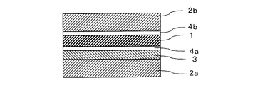
図2は、図1で得られた偏光板における、保護フィルム(2a)を設けていない側の偏光子(1)に、接着剤層(4b)を介して透明保護フィルム(2b)が設けられている偏光板の断面図である。透明保護フィルム(2b)は、環状オレフィン系樹脂を主成分とする透明保護フィルム(2a)を用いることができる他、透明保護フィルム(2a)以外の材料のものを用いることができる。また、接着剤層(4b)は、ポリビニルアルコール系接着剤層(4a)を用いることができる他、接着剤層(4a)以外の材料を用いることができる。また接着剤層(4b)は、樹脂層(3)を介して設けることができる。偏光子(1)の両側に保護フィルム(2)を設ける場合には、両側の保護フィルム(2)を同時に貼り合わせてもよく、逐次に貼り合わせてもよい。 FIG. 2 shows that the polarizing plate obtained in FIG. 1 is provided with a transparent protective film (2b) through an adhesive layer (4b) on the polarizer (1) on the side where the protective film (2a) is not provided. It is sectional drawing of the polarizing plate which is. The transparent protective film (2b) can be made of a material other than the transparent protective film (2a), in addition to the transparent protective film (2a) containing a cyclic olefin resin as a main component. The adhesive layer (4b) can be made of a material other than the adhesive layer (4a) in addition to the polyvinyl alcohol-based adhesive layer (4a). The adhesive layer (4b) can be provided via the resin layer (3). When providing a protective film (2) on both sides of the polarizer (1), the protective films (2) on both sides may be bonded simultaneously or sequentially.
図1、図2では樹脂層(3)は1層の場合が例示されているが、樹脂層(3)は複数層設けることができる。 1 and 2 exemplify the case where the resin layer (3) is a single layer, a plurality of resin layers (3) can be provided.
偏光子(1)は、特に制限されず、各種のものを使用できる。偏光子としては、たとえば、ポリビニルアルコール系フィルム、部分ホルマール化ポリビニルアルコール系フィルム、エチレン・酢酸ビニル共重合体系部分ケン化フィルム等の親水性高分子フィルムに、ヨウ素や二色性染料等の二色性材料を吸着させて一軸延伸したもの、ポリビニルアルコールの脱水処理物やポリ塩化ビニルの脱塩酸処理物等ポリエン系配向フィルム等があげられる。これらのなかでもポリビニルアルコール系フィルムとヨウ素、二色性染料などの二色性物質からなる偏光子が好適である。 The polarizer (1) is not particularly limited, and various types can be used. Examples of the polarizer include hydrophilic polymer films such as polyvinyl alcohol film, partially formalized polyvinyl alcohol film, and ethylene / vinyl acetate copolymer partially saponified film, and two colors such as iodine and dichroic dye. And polyene-based oriented films such as those obtained by adsorbing a functional material and uniaxially stretched, polyvinyl alcohol dehydrated products, and polyvinyl chloride dehydrochlorinated products. Among these, a polarizer made of a dichroic substance such as a polyvinyl alcohol film and iodine or a dichroic dye is preferable.
ポリビニルアルコール系フィルムとしては、ポリビニルアルコール系樹脂を、水またはは有機溶媒に溶解した原液を流延成膜する流延法、キャスト法、押出法等の任意の方法で成膜されたものを適宜使用することができる。ポリビニルアルコール系樹脂の重合度は100〜5000程度が好ましく、1400〜4000がより好ましい。 As the polyvinyl alcohol-based film, a film formed by any method such as a casting method, a casting method, an extrusion method, etc., in which a polyvinyl alcohol-based resin is cast in a stock solution in which water or an organic solvent is dissolved, is appropriately used. Can be used. The degree of polymerization of the polyvinyl alcohol-based resin is preferably about 100 to 5000, and more preferably 1400 to 4000.
ポリビニルアルコール系フィルムをヨウ素等で染色し一軸延伸した偏光子は、たとえば、以下の方法により作成できる。 A polarizer obtained by dyeing a polyvinyl alcohol-based film with iodine or the like and uniaxially stretching can be produced, for example, by the following method.
染色工程においては、ポリビニルアルコール系フィルムを、ヨウ素が添加された20〜70℃程度の染色浴に1〜20分間程度浸漬し、ヨウ素を吸着させる。染色浴中のヨウ素濃度は、通常、水100重量部あたり0.1〜1重量部程度である。染色浴中には、ヨウ化カリウム、ヨウ化リチウム、ヨウ化ナトリウム、ヨウ化亜鉛、ヨウ化アルミニウム、ヨウ化鉛、ヨウ化銅、ヨウ化バリウム、ヨウ化カルシウム、ヨウ化錫、ヨウ化チタン等のヨウ化物等の助剤を通常、水100重量部あたり0.01〜20重量部程度、好ましくは0.02〜10重量部添加してもよい。これら添加物は、染色効率を高める上で特に好ましい。また水溶媒以外に、水と相溶性のある有機溶媒が少量含有されていてもよい。 In the dyeing process, the polyvinyl alcohol film is immersed in a dyeing bath at about 20 to 70 ° C. to which iodine is added for about 1 to 20 minutes to adsorb iodine. The iodine concentration in the dyeing bath is usually about 0.1 to 1 part by weight per 100 parts by weight of water. In the dyeing bath, potassium iodide, lithium iodide, sodium iodide, zinc iodide, aluminum iodide, lead iodide, copper iodide, barium iodide, calcium iodide, tin iodide, titanium iodide, etc. In general, an auxiliary such as iodide may be added in an amount of about 0.01 to 20 parts by weight, preferably 0.02 to 10 parts by weight per 100 parts by weight of water. These additives are particularly preferable for increasing the dyeing efficiency. In addition to the water solvent, a small amount of an organic solvent compatible with water may be contained.
またポリビニルアルコール系フィルムは、ヨウ素または二色性染料含有水溶液中で染色させる前に、水浴等において20〜60℃程度で0.1〜10分間程度膨潤処理されていてもよい。ポリビニルアルコール系フィルムを水洗することでポリビニルアルコール系フィルム表面の汚れやブロッキング防止剤を洗浄することができるほかに、ポリビニルアルコール系フィルムを膨潤させることで染色のムラなどの不均一を防止する効果もある。 The polyvinyl alcohol film may be subjected to a swelling treatment at about 20 to 60 ° C. for about 0.1 to 10 minutes in a water bath or the like before being dyed in an aqueous solution containing iodine or a dichroic dye. In addition to washing the polyvinyl alcohol film surface with dirt and anti-blocking agents by washing the polyvinyl alcohol film with water, it also has the effect of preventing unevenness such as uneven coloring by swelling the polyvinyl alcohol film. is there.
染色処理したポリビニルアルコール系フィルムは、必要に応じて架橋することができる。架橋処理を行なう架橋水溶液の組成は、通常水100重量部あたりホウ酸、ホウ砂、グリオキザール、グルタルアルデヒド等の架橋剤を単独又は混合して1〜10重量部程度である。架橋剤の濃度は、光学特性とポリビニルアルコール系フィルムに発生する延伸力により生じる偏光板収縮のバランスを考慮して決定される。 The dyed polyvinyl alcohol film can be cross-linked as necessary. The composition of the aqueous crosslinking solution used for the crosslinking treatment is usually about 1 to 10 parts by weight with 100 parts by weight of water alone or mixed with a crosslinking agent such as boric acid, borax, glyoxal, and glutaraldehyde. The concentration of the crosslinking agent is determined in consideration of the balance between the optical properties and the contraction of the polarizing plate caused by the stretching force generated in the polyvinyl alcohol film.
架橋浴中には、ヨウ化カリウム、ヨウ化リチウム、ヨウ化ナトリウム、ヨウ化亜鉛、ヨウ化アルミニウム、ヨウ化鉛、ヨウ化銅、ヨウ化バリウム、ヨウ化カルシウム、ヨウ化錫、ヨウ化チタン等のヨウ化物等の助剤を濃度0.05〜15重量%、好ましくは0.5〜8重量%となるように添加してもよい。これら添加剤は、偏光子の面内の均一な特性を得る点で特に好ましい。水溶液の温度は通常20〜70℃程度、好ましくは40〜60℃の範囲である。浸漬時間は、特に限定されないが、通常1秒〜15分間程度、好ましくは5秒〜10分間である。水溶媒以外に、水と相溶性のある有機溶媒が少量含有されていてもよい。 In the crosslinking bath, potassium iodide, lithium iodide, sodium iodide, zinc iodide, aluminum iodide, lead iodide, copper iodide, barium iodide, calcium iodide, tin iodide, titanium iodide, etc. Aids such as iodide may be added to a concentration of 0.05 to 15% by weight, preferably 0.5 to 8% by weight. These additives are particularly preferable from the viewpoint of obtaining in-plane uniform characteristics of the polarizer. The temperature of the aqueous solution is usually about 20 to 70 ° C, preferably 40 to 60 ° C. The immersion time is not particularly limited, but is usually about 1 second to 15 minutes, preferably 5 seconds to 10 minutes. In addition to the water solvent, a small amount of an organic solvent compatible with water may be contained.
ポリビニルアルコール系フィルムの総延伸倍率は元長の3〜7倍程度、好ましくは5〜7倍である。総延伸倍率が7倍を超える場合はフィルムが破断しやすくなる。延伸はヨウ素で染色した後に行なっても良いし、染色または架橋しながら延伸してもよし、また延伸してからヨウ素で染色してもよい。延伸方法や延伸回数等は、特に制限されるものではなく、いずれか一工程でのみ行なってもよい。また、同一工程で複数回行なってもよい。 The total draw ratio of the polyvinyl alcohol film is about 3 to 7 times, preferably 5 to 7 times the original length. When the total draw ratio exceeds 7 times, the film is easily broken. Stretching may be performed after dyeing with iodine, may be performed while dyeing or crosslinking, or may be dyed with iodine after stretching. The stretching method, the number of stretching, etc. are not particularly limited, and may be performed only in any one step. Moreover, you may carry out in multiple times by the same process.
またヨウ素吸着配向処理を施したポリビニルアルコール系フィルムには、さらに水温10〜60℃程度、好ましくは30〜40℃程度、濃度0.1〜10重量%のヨウ化カリウム等のヨウ化物水溶液に1秒〜1分間浸漬する工程を設けることができる。ヨウ化物水溶液中には、硫酸亜鉛、塩化亜鉛物等の助剤を添加してもよい。また、ヨウ素吸着配向処理を施したポリビニルアルコール系フィルムには、水洗工程、20〜80℃程度で1分〜10分間程度の乾燥工程を設けることができる。 In addition, the polyvinyl alcohol film subjected to iodine adsorption alignment treatment is further added to an aqueous iodide solution such as potassium iodide having a water temperature of about 10 to 60 ° C., preferably about 30 to 40 ° C. and a concentration of 0.1 to 10% by weight. A step of dipping for 1 minute to 1 minute can be provided. In the iodide aqueous solution, auxiliary agents such as zinc sulfate and zinc chloride may be added. The polyvinyl alcohol film subjected to the iodine adsorption alignment treatment can be provided with a water washing step and a drying step of about 20 to 80 ° C. for about 1 minute to 10 minutes.
これら偏光子(1)の厚さは特に制限されないが、一般的に、5〜80μm程度である。偏光子の厚みが薄くなると、偏光板の製造工程中において、透明保護フィルムと貼り合せる際の乾燥工程等において、偏光子中の水分が揮発しやすくなる。そのため偏光子の伸度が低減し、顕著なスジ状外観欠点が発生しやすくなる。このような現象は特に厚さ20μm以下の偏光子に顕著に表れるが、本発明の偏光板の製造方法によれば、偏光子の厚さが20μm以下の場合であってもスジ状外観欠点の発生を抑えることができる。 The thickness of these polarizers (1) is not particularly limited, but is generally about 5 to 80 μm. When the thickness of the polarizer is reduced, the moisture in the polarizer is likely to be volatilized in the drying process for bonding with the transparent protective film during the manufacturing process of the polarizing plate. Therefore, the elongation of the polarizer is reduced, and a noticeable streak-like appearance defect is likely to occur. Such a phenomenon is particularly prominent in a polarizer having a thickness of 20 μm or less. However, according to the method for producing a polarizing plate of the present invention, even when the thickness of the polarizer is 20 μm or less, a streaky appearance defect is caused. Occurrence can be suppressed.
透明保護フィルム(2a)の主成分である環状オレフィン系樹脂は一般的な総称であり、たとえば、特開平3−14882号公報、特開平3−122137号公報等に記載されている。具体的には環状オレフィンの開環重合体、環状オレフィンの付加重合体、環状オレフィンとエチレン、プロピレン等のα−オレフィンとのランダム共重合体、またこれらを不飽和カルボン酸やその誘導体等で変性したグラフト変性体等が例示できる。さらには、これらの水素化物があげられる。環状オレフィンは特に限定するものではないが、例えば、ノルボルネン、テトラシクロドデセンや、それらの誘導体が例示できる。商品としては、日本ゼオン(株)製のゼオネックス、ゼオノア、JSR(株)製のアートン等があげられる。 The cyclic olefin-based resin that is the main component of the transparent protective film (2a) is a general generic name, and is described, for example, in JP-A Nos. 3-14882 and 3-122137. Specifically, ring-opening polymers of cyclic olefins, addition polymers of cyclic olefins, random copolymers of cyclic olefins and α-olefins such as ethylene and propylene, and these are modified with unsaturated carboxylic acids or their derivatives. Examples of such graft-modified products can be given. Furthermore, these hydrides are mentioned. The cyclic olefin is not particularly limited, and examples thereof include norbornene, tetracyclododecene, and derivatives thereof. Examples of the products include ZEONEX, ZEONOR manufactured by Nippon Zeon Co., Ltd., and ARTON manufactured by JSR Corporation.
本発明では、片側の透明保護フィルム(2a)には環状オレフィン系樹脂を主成分とするものが用いられるが、他の片側の透明保護フィルム(2b)には環状オレフィン系樹脂以外の材料を主成分とするものを用いることができる。透明保護フィルム(2b)を形成する透明ポリマーまたはフィルム材料としては、環状オレフィン系樹脂の他に、適宜な透明材料を用いうるが、透明性や機械的強度、熱安定性や水分遮断性などに優れるものが好ましく用いられる。例えばポリエチレンテレフタレートやポリエチレンナフタレート等のポリエステル系ポリマー、二酢酸セルロースや三酢酸セルロース等のセルロース系ポリマー、ポリメチルメタクリレート等のアクリル系ポリマー、ポリスチレンやアクリロニトリル・スチレン共重合体(AS樹脂)等のスチレン系ポリマー、ポリカーボネート系ポリマーなどがあげられる。また、ポリエチレン、ポリプロピレン等のポリオレフィン、エチレン・プロピレン共重合体の如きポリオレフィン系ポリマー、塩化ビニル系ポリマー、ナイロンや芳香族ポリアミド等のアミド系ポリマー、イミド系ポリマー、スルホン系ポリマー、ポリエーテルスルホン系ポリマー、ポリエーテルエーテルケトン系ポリマー、ポリフェニレンスルフィド系ポリマー、ビニルアルコール系ポリマー、塩化ビニリデン系ポリマー、ビニルブチラール系ポリマー、アリレート系ポリマー、ポリオキシメチレン系ポリマー、エポキシ系ポリマー、あるいは前記ポリマーのブレンド物なども前記透明保護フィルムを形成するポリマーの例としてあげられる。透明保護フィルムは、アクリル系、ウレタン系、アクリルウレタン系、エポキシ系、シリコーン系等の熱硬化型、紫外線硬化型の樹脂の硬化層として形成することもできる。 In the present invention, the transparent protective film (2a) on one side is mainly composed of a cyclic olefin resin, but the other transparent protective film (2b) is mainly made of a material other than the cyclic olefin resin. What is used as a component can be used. As the transparent polymer or film material for forming the transparent protective film (2b), an appropriate transparent material can be used in addition to the cyclic olefin resin, but the transparency, mechanical strength, thermal stability, moisture barrier property, etc. An excellent material is preferably used. For example, polyester polymers such as polyethylene terephthalate and polyethylene naphthalate, cellulose polymers such as cellulose diacetate and cellulose triacetate, acrylic polymers such as polymethyl methacrylate, styrene such as polystyrene and acrylonitrile / styrene copolymer (AS resin) -Based polymer, polycarbonate-based polymer and the like. Polyolefins such as polyethylene and polypropylene, polyolefin polymers such as ethylene / propylene copolymers, vinyl chloride polymers, amide polymers such as nylon and aromatic polyamide, imide polymers, sulfone polymers, polyethersulfone polymers , Polyether ether ketone polymers, polyphenylene sulfide polymers, vinyl alcohol polymers, vinylidene chloride polymers, vinyl butyral polymers, arylate polymers, polyoxymethylene polymers, epoxy polymers, or blends of the above polymers Examples of the polymer forming the transparent protective film are mentioned. The transparent protective film can also be formed as a cured layer of thermosetting or ultraviolet curable resin such as acrylic, urethane, acrylurethane, epoxy, and silicone.
また、特開2001−343529号公報(WO01/37007)に記載のポリマーフィルム、たとえば、(A)側鎖に置換および/または非置換イミド基を有する熱可塑性樹脂と、(B)側鎖に置換および/または非置換フェニルならびにニトリル基を有する熱可塑性樹脂を含有する樹脂組成物があげられる。具体例としてはイソブチレンとN−メチルマレイミドからなる交互共重合体とアクリロニトリル・スチレン共重合体とを含有する樹脂組成物のフィルムがあげられる。フィルムは樹脂組成物の混合押出品などからなるフィルムを用いることができる。これらのフィルムは位相差が小さく、光弾性係数が小さいため偏光板の歪みによるムラなどの不具合を解消することができ、また透湿度が小さいため、加湿耐久性に優れる。 Moreover, the polymer film described in JP-A-2001-343529 (WO01 / 37007), for example, (A) a thermoplastic resin having a substituted and / or unsubstituted imide group in the side chain, and (B) a substitution in the side chain And / or a resin composition containing a thermoplastic resin having unsubstituted phenyl and a nitrile group. A specific example is a film of a resin composition containing an alternating copolymer composed of isobutylene and N-methylmaleimide and an acrylonitrile / styrene copolymer. As the film, a film made of a mixed extruded product of the resin composition or the like can be used. Since these films have a small phase difference and a small photoelastic coefficient, problems such as unevenness due to the distortion of the polarizing plate can be eliminated, and since the moisture permeability is small, the humidification durability is excellent.
また、透明保護フィルム(2b)は、できるだけ色付きがないことが好ましい。したがって、Rth=[(nx+ny)/2−nz]・d(ただし、nx、nyはフィルム平面内の主屈折率、nzはフィルム厚方向の屈折率、dはフィルム厚みである)で表されるフィルム厚み方向の位相差値が−90nm〜+75nmである透明保護フィルムが好ましく用いられる。かかる厚み方向の位相差値(Rth)が−90nm〜+75nmのものを使用することにより、透明保護フィルムに起因する偏光板の着色(光学的な着色)をほぼ解消することができる。厚み方向位相差値(Rth)は、さらに好ましくは−80nm〜+60nm、特に−70nm〜+45nmが好ましい。 Moreover, it is preferable that a transparent protective film (2b) is as colored as possible. Therefore, Rth = [(nx + ny) / 2−nz] · d (where nx and ny are the main refractive index in the plane of the film, nz is the refractive index in the film thickness direction, and d is the film thickness). A transparent protective film having a retardation value in the film thickness direction of −90 nm to +75 nm is preferably used. By using a film having a thickness direction retardation value (Rth) of −90 nm to +75 nm, the coloring (optical coloring) of the polarizing plate caused by the transparent protective film can be almost eliminated. The thickness direction retardation value (Rth) is more preferably −80 nm to +60 nm, and particularly preferably −70 nm to +45 nm.
透明保護フィルム(2a)、(2b)の厚さは、適宜に決定しうるが、一般には強度や取扱性等の作業性、薄層性などの点より1〜500μm程度である。特に1〜300μmが好ましく、5〜200μmがより好ましい。透明保護フィルム(2)の厚さは、50μm以下であるものが好ましく用いられる。 The thickness of the transparent protective films (2a) and (2b) can be appropriately determined, but is generally about 1 to 500 μm from the viewpoints of workability such as strength and handleability, and thin layer properties. 1-300 micrometers is especially preferable, and 5-200 micrometers is more preferable. The thickness of the transparent protective film (2) is preferably 50 μm or less.
前記透明保護フィルム(2a)、(2b)の偏光子を接着させない面には、ハードコート層や反射防止処理、スティッキング防止や、拡散ないしアンチグレアを目的とした処理を施したものであってもよい。 The surface of the transparent protective films (2a) and (2b) to which the polarizer is not adhered may be subjected to a hard coat layer, an antireflection treatment, an antisticking treatment, or a treatment for diffusion or antiglare. .
ハードコート処理は偏光板表面の傷付き防止などを目的に施されるものであり、例えばアクリル系、シリコーン系などの適宜な紫外線硬化型樹脂による硬度や滑り特性等に優れる硬化皮膜を透明保護フィルムの表面に付加する方式などにて形成することができる。反射防止処理は偏光板表面での外光の反射防止を目的に施されるものであり、従来に準じた反射防止膜などの形成により達成することができる。また、スティッキング防止処理は隣接層との密着防止を目的に施される。 The hard coat treatment is applied for the purpose of preventing scratches on the surface of the polarizing plate. For example, a transparent protective film with a cured film excellent in hardness, sliding properties, etc. by an appropriate ultraviolet curable resin such as acrylic or silicone is used. It can be formed by a method of adding to the surface of the film. The antireflection treatment is performed for the purpose of preventing reflection of external light on the surface of the polarizing plate, and can be achieved by forming an antireflection film or the like according to the conventional art. Further, the anti-sticking treatment is performed for the purpose of preventing adhesion with an adjacent layer.
またアンチグレア処理は偏光板の表面で外光が反射して偏光板透過光の視認を阻害することの防止等を目的に施されるものであり、例えばサンドブラスト方式やエンボス加工方式による粗面化方式や透明微粒子の配合方式などの適宜な方式にて透明保護フィルムの表面に微細凹凸構造を付与することにより形成することができる。前記表面微細凹凸構造の形成に含有させる微粒子としては、例えば平均粒径が0.5〜20μmのシリカ、アルミナ、チタニア、ジルコニア、酸化錫、酸化インジウム、酸化カドミウム、酸化アンチモン等からなる導電性のこともある無機系微粒子、架橋又は未架橋のポリマー等からなる有機系微粒子などの透明微粒子が用いられる。表面微細凹凸構造を形成する場合、微粒子の使用量は、表面微細凹凸構造を形成する透明樹脂100重量部に対して一般的に2〜70重量部程度であり、5〜50重量部が好ましい。アンチグレア層は、偏光板透過光を拡散して視角などを拡大するための拡散層(視角拡大機能等)を兼ねるものであってもよい。 The anti-glare treatment is applied for the purpose of preventing the outside light from being reflected on the surface of the polarizing plate and obstructing the visibility of the light transmitted through the polarizing plate. For example, the surface is roughened by a sandblasting method or an embossing method. It can be formed by imparting a fine concavo-convex structure to the surface of the transparent protective film by an appropriate method such as a blending method of transparent particles. Examples of the fine particles to be included in the formation of the surface fine concavo-convex structure include conductive materials made of silica, alumina, titania, zirconia, tin oxide, indium oxide, cadmium oxide, antimony oxide, and the like having an average particle diameter of 0.5 to 20 μm. In some cases, transparent fine particles such as inorganic fine particles, organic fine particles made of a crosslinked or uncrosslinked polymer, etc. are used. When forming the surface fine uneven structure, the amount of fine particles used is generally about 2 to 70 parts by weight, preferably 5 to 50 parts by weight, based on 100 parts by weight of the transparent resin forming the surface fine uneven structure. The antiglare layer may also serve as a diffusion layer (viewing angle expanding function or the like) for diffusing the light transmitted through the polarizing plate to expand the viewing angle.
なお、前記反射防止層、スティッキング防止層、拡散層やアンチグレア層等は、透明保護フィルムそのものに設けることができるほか、別途光学層として透明透明保護フィルム(2a)、(2b)とは別体のものとして設けることもできる。 The antireflection layer, antisticking layer, diffusion layer, antiglare layer and the like can be provided on the transparent protective film itself, and separately from the transparent transparent protective films (2a) and (2b) as an optical layer. It can also be provided.
樹脂層(3)は、環状オレフィン系樹脂を主成分とする透明保護フィルム(2a)と良好に密着すれば特に制限されない。たとえば、エステル系、エーテル系、カーボネート系、ウレタン系、シリコーン系等の各種樹脂を用いることができる。前記樹脂層(3)は水系、溶剤系のいずれでもよい。なかでも水系ウレタン樹脂やシリコーン系樹脂が好ましい。さらに上記樹脂層を形成する樹脂には、シランカップリング剤やチタンカップリング剤などのカップリング剤、そのカップリング剤を効率よく反応させるためのチタン系、錫系等の触媒を添加することができる。これにより一層ポリビニルアルコール偏光子(1)と透明保護フィルム(2a)との接着力をより強固にすることができる。また上記樹脂層(3)には他の添加剤を加えてもよい。具体的にはさらにはテルペン樹脂、フェノール樹脂、テルペン−フェノール樹脂、ロジン樹脂、キシレン樹脂などの粘着付与剤、紫外線吸収剤、酸化防止剤、耐熱安定剤などの安定剤等を用いてもよい。 The resin layer (3) is not particularly limited as long as it is in good contact with the transparent protective film (2a) containing a cyclic olefin resin as a main component. For example, various resins such as ester, ether, carbonate, urethane, and silicone can be used. The resin layer (3) may be either water-based or solvent-based. Of these, water-based urethane resins and silicone resins are preferable. Furthermore, it is possible to add a coupling agent such as a silane coupling agent or a titanium coupling agent to the resin that forms the resin layer, and a catalyst such as a titanium-based or tin-based catalyst for efficiently reacting the coupling agent. it can. Thereby, the adhesive force between the polyvinyl alcohol polarizer (1) and the transparent protective film (2a) can be further strengthened. Moreover, you may add another additive to the said resin layer (3). Specifically, terpene resins, phenol resins, terpene-phenol resins, rosin resins, xylene resins and other tackifiers, UV absorbers, antioxidants, heat stabilizers and other stabilizers may be used.
上記樹脂層(3)は、乾燥後の厚み、塗工の円滑性などを考慮して適当な濃度に希釈した溶液を公知の技術により塗工、乾燥することにより形成される。前記樹脂層(3)は乾燥後の厚みが、好ましくは0.01〜10μm、さらに好ましくは0.1〜2μmである。樹脂層(3)を複数層設ける場合にも、樹脂層(3)の総厚みは前記範囲になるようにするのが好ましい。 The resin layer (3) is formed by coating and drying a solution diluted to an appropriate concentration in consideration of the thickness after drying, the smoothness of coating, and the like by a known technique. The resin layer (3) preferably has a thickness after drying of 0.01 to 10 μm, more preferably 0.1 to 2 μm. Even when a plurality of resin layers (3) are provided, the total thickness of the resin layers (3) is preferably within the above range.
なお、透明保護フィルム(2b)の偏光子と接着する面には、樹脂層(3)を設けることができる他、易接着処理を施すことができる。易接着処理としては、プラズマ処理、コロナ処理等のドライ処理、アルカリ処理等の化学処理、易接着剤層を形成するコーティング処理等があげられる。 In addition, the surface which adheres with the polarizer of a transparent protective film (2b) can provide an easily bonding process other than providing a resin layer (3). Examples of the easy adhesion treatment include dry treatment such as plasma treatment and corona treatment, chemical treatment such as alkali treatment, and coating treatment for forming an easy adhesive layer.
ポリビニルアルコール系接着剤層(4a)の形成には、通常、偏光子と透明保護フィルムの形成に用いられるポリビニルアルコール系接着剤を特に制限なく使用できる。 For the formation of the polyvinyl alcohol-based adhesive layer (4a), a polyvinyl alcohol-based adhesive generally used for forming a polarizer and a transparent protective film can be used without particular limitation.
ポリビニルアルコール系樹脂は、ポリ酢酸ビニルをケン化して得られたポリビニルアルコール;その誘導体;更に酢酸ビニルと共重合性を有する単量体との共重合体のケン化物;ポリビニルアルコールをアセタール化、ウレタン化、エーテル化、グラフト化、リン酸エステル化等した変性ポリビニルアルコールがあげられる。前記単量体としては、(無水)マレイン酸、フマール酸、クロトン酸、イタコン酸、(メタ)アクリル酸等の不飽和カルボン酸及びそのエステル類;エチレン、プロピレン等のα−オレフィン、(メタ)アリルスルホン酸(ソーダ)、スルホン酸ソーダ(モノアルキルマレート)、ジスルホン酸ソーダアルキルマレート、N−メチロールアクリルアミド、アクリルアミドアルキルスルホン酸アルカリ塩、N−ビニルピロリドン、N−ビニルピロリドン誘導体等があげられる。これらポリビニルアルコール系樹脂は一種を単独でまたは二種以上を併用することができる。 Polyvinyl alcohol resin is polyvinyl alcohol obtained by saponifying polyvinyl acetate; a derivative thereof; a saponified product of a copolymer of vinyl acetate and a monomer having copolymerizability; Examples thereof include modified polyvinyl alcohols that have been converted into ethers, ethers, grafts, or phosphoric esters. Examples of the monomer include unsaturated carboxylic acids such as (anhydrous) maleic acid, fumaric acid, crotonic acid, itaconic acid, (meth) acrylic acid, and esters thereof; α-olefins such as ethylene and propylene, (meth) Examples include allyl sulfonic acid (soda), sulfonic acid soda (monoalkyl malate), disulfonic acid soda alkyl maleate, N-methylol acrylamide, acrylamide alkyl sulfonic acid alkali salt, N-vinyl pyrrolidone, N-vinyl pyrrolidone derivatives, and the like. . These polyvinyl alcohol resins can be used singly or in combination of two or more.
前記ポリビニルアルコール系樹脂は特に限定されないが、接着性の点からは、平均重合度100〜3000程度、好ましくは500〜3000、平均ケン化度85〜100モル%程度、好ましくは90〜100モル%である。 The polyvinyl alcohol-based resin is not particularly limited, but from the viewpoint of adhesion, the average degree of polymerization is about 100 to 3000, preferably 500 to 3000, the average saponification degree is about 85 to 100 mol%, preferably 90 to 100 mol%. It is.
またポリビニルアルコール系樹脂としては、アセトアセチル基を有するポリビニルアルコール樹脂を用いることができる。アセトアセチル基を有するポリビニルアルコール樹脂は、反応性の高い官能基を有するポリビニルアルコール系接着剤であり、偏光板の耐久性が向上し好ましい。 Moreover, as a polyvinyl alcohol-type resin, the polyvinyl alcohol resin which has an acetoacetyl group can be used. The polyvinyl alcohol resin having an acetoacetyl group is a polyvinyl alcohol-based adhesive having a highly reactive functional group, and is preferable because the durability of the polarizing plate is improved.
アセトアセチル基を含有するポリビニルアルコール系樹脂は、ポリビニルアルコール系樹脂とジケテンとを公知の方法で反応して得られる。たとえば、ポリビニルアルコール系樹脂を酢酸等の溶媒中に分散させておき、これにジケテンを添加する方法、ポリビニルアルコール系樹脂をジメチルホルムアミドまたはジオキサン等の溶媒にあらかじめ溶解しておき、これにジケテンを添加する方法等があげられる。またポリビニルアルコールにジケテンガスまたは液状ジケテンを直接接触させる方法があげられる。 A polyvinyl alcohol-based resin containing an acetoacetyl group is obtained by reacting a polyvinyl alcohol-based resin with diketene by a known method. For example, a method in which a polyvinyl alcohol resin is dispersed in a solvent such as acetic acid and diketene is added thereto, a polyvinyl alcohol resin is previously dissolved in a solvent such as dimethylformamide or dioxane, and diketene is added thereto. And the like. Another example is a method in which diketene gas or liquid diketene is brought into direct contact with polyvinyl alcohol.
アセトアセチル基を含有するポリビニルアルコール系樹脂のアセトアセチル基変性度は、0.1モル%以上であれば特に制限はなない。0.1モル%未満では接着剤層の耐水性が不充分であり不適当である。アセトアセチル基変性度は、好ましくは0.1〜40モル%程度、さらに好ましくは1〜20モル%である。アセトアセチル基変性度が40モル%を超えると架橋剤との反応点が少なくなり、耐水性の向上効果が小さい。アセトアセチル基変性度はNMRにより測定した値である。 The degree of acetoacetyl group modification of the polyvinyl alcohol-based resin containing an acetoacetyl group is not particularly limited as long as it is 0.1 mol% or more. If it is less than 0.1 mol%, the water resistance of the adhesive layer is insufficient and unsuitable. The degree of acetoacetyl modification is preferably about 0.1 to 40 mol%, more preferably 1 to 20 mol%. When the degree of acetoacetyl modification exceeds 40 mol%, the number of reaction points with the cross-linking agent decreases, and the effect of improving water resistance is small. The degree of acetoacetyl modification is a value measured by NMR.
本発明の製造方法では、スジ状外観欠点の抑制に、反応性の高い接着剤の方が、反応性の低い接着剤よりもその効果が大きいことも分かった。そのメカニズムは必ずしも明らかではない。反応性の低い接着剤は、一般的に水に対する溶解性が高いため、一旦透明保護フィルムの表面に形成された接着剤層が、添加された水性液中に再溶解する。そして、貼り合わされる相手である偏光子表面近傍において、添加水溶液系の粘度を増加させるためではないかと考えられる。したがって、本発明の製造方法は、反応性の高いポリビニルアルコール系接着剤を用いる場合に特に有効であり、ポリビニルアルコール系接着剤としては、アセトアセチル基を有するポリビニルアルコール系接着剤が接着性が良好である。 In the production method of the present invention, it was also found that a highly reactive adhesive has a greater effect than a less reactive adhesive in suppressing streaky appearance defects. The mechanism is not always clear. Since an adhesive having low reactivity is generally highly soluble in water, the adhesive layer once formed on the surface of the transparent protective film is redissolved in the added aqueous liquid. And it is thought that it may be for increasing the viscosity of the added aqueous solution system in the vicinity of the surface of the polarizer, which is the partner to be bonded. Therefore, the production method of the present invention is particularly effective when a highly reactive polyvinyl alcohol-based adhesive is used. As the polyvinyl alcohol-based adhesive, a polyvinyl alcohol-based adhesive having an acetoacetyl group has good adhesiveness. It is.
ポリビニルアルコール系接着剤は、架橋剤を含有するものを用いることができる。水性液(5)として水を用いる場合に特に有効である。水性液(5)として、架橋剤を含有する水溶液を用いる場合には、接着剤中には架橋剤を含有していてもよく、また含有していなくてもよい。 As the polyvinyl alcohol-based adhesive, one containing a crosslinking agent can be used. This is particularly effective when water is used as the aqueous liquid (5). When an aqueous solution containing a crosslinking agent is used as the aqueous liquid (5), the adhesive may or may not contain a crosslinking agent.
架橋剤としては、ポリビニルアルコール系接着剤に用いられているものを特に制限なく使用できる。当該架橋剤については、後述する。前記架橋剤の配合量は、ポリビニルアルコール系樹脂100重量部に対して、通常、0.1〜35重量部程度、好ましくは10〜25重量部である。かかる範囲において、均一な偏光特性を有し、かつ耐久性の優れた偏光板が得られる。一方、耐久性をより向上させるには、ポリビニルアルコール系樹脂100重量部に対して、架橋剤を30重量部を超え46重量部以下の範囲で配合することができる。特に、アセトアセチル基を含有するポリビニルアルコール系樹脂を用いる場合には、架橋剤の使用量を30重量部を超えて用いるのが好ましい。架橋剤を30重量部を超え46重量部以下の範囲で配合することにより、耐水性が飛躍的に向上させることができる。架橋剤の配合量は、前記範囲内で多いほど好ましく、31重量部以上、さらには32重量部以上、特に35重量部以上が好ましい。一方、架橋剤の配合量が多くなりすぎると、架橋剤の反応が短時間で進行し、接着剤がゲル化する傾向がある。その結果、接着剤としての可使時間(ポットライフ)が極端に短くなり、工業的な使用が困難になる。かかる観点からは、架橋剤の配合量は、46重量部以下、さらには45重量部以下、特に40重量部以下とするのが好ましい。 As a crosslinking agent, what is used for the polyvinyl alcohol-type adhesive agent can be especially used without a restriction | limiting. The crosslinking agent will be described later. The amount of the crosslinking agent is usually about 0.1 to 35 parts by weight, preferably 10 to 25 parts by weight, with respect to 100 parts by weight of the polyvinyl alcohol resin. In such a range, a polarizing plate having uniform polarization characteristics and excellent durability can be obtained. On the other hand, in order to further improve the durability, the crosslinking agent can be blended in an amount exceeding 30 parts by weight and not more than 46 parts by weight with respect to 100 parts by weight of the polyvinyl alcohol resin. In particular, when a polyvinyl alcohol-based resin containing an acetoacetyl group is used, it is preferable to use the crosslinking agent in an amount exceeding 30 parts by weight. By blending the crosslinking agent in the range of more than 30 parts by weight and 46 parts by weight or less, the water resistance can be drastically improved. The blending amount of the crosslinking agent is preferably as large as possible within the above range, and is preferably 31 parts by weight or more, more preferably 32 parts by weight or more, and particularly preferably 35 parts by weight or more. On the other hand, if the amount of the crosslinking agent is too large, the reaction of the crosslinking agent proceeds in a short time and the adhesive tends to gel. As a result, the pot life as an adhesive is extremely shortened, making industrial use difficult. From such a viewpoint, the blending amount of the crosslinking agent is preferably 46 parts by weight or less, more preferably 45 parts by weight or less, and particularly preferably 40 parts by weight or less.
なお、前記接着剤には、さらにシランカップリング剤、チタンカップリング剤などのカップリング剤、各種粘着付与剤、紫外線吸収剤、酸化防止剤、耐熱安定剤、耐加水分解安定剤などの安定剤等を配合することもできる。 The adhesive further includes a silane coupling agent, a coupling agent such as a titanium coupling agent, various tackifiers, an ultraviolet absorber, an antioxidant, a heat stabilizer, a hydrolysis stabilizer, and the like. Etc. can also be blended.
ポリビニルアルコール接着剤層(4a)は、ポリビニルアルコール系接着剤(水溶液)を塗工、乾燥することにより形成することができる。水溶液にはエタノール等の溶剤を適宜に含有させることができる。水溶液濃度は、接着性、塗工の円滑性などを考慮して適当な濃度に調整されるが、例えば1〜20重量%程度が好ましい。塗工方法は従来公知の技術により行うことができる。 The polyvinyl alcohol adhesive layer (4a) can be formed by coating and drying a polyvinyl alcohol-based adhesive (aqueous solution). The aqueous solution can appropriately contain a solvent such as ethanol. The concentration of the aqueous solution is adjusted to an appropriate concentration in consideration of adhesiveness, coating smoothness, and the like, and is preferably about 1 to 20% by weight, for example. The coating method can be performed by a conventionally known technique.
ポリビニルアルコール接着剤層(4a)の厚みは、乾燥後の厚みで厚くなりすぎると、偏光子(1)と透明保護フィルム(2a)の接着性の点で好ましくないことから20μm以下にするのが好ましい。より好ましくは0.01〜10μm、さらに好ましくは0.1〜5μmである。 When the thickness of the polyvinyl alcohol adhesive layer (4a) becomes too thick after drying, it is not preferable in terms of the adhesiveness between the polarizer (1) and the transparent protective film (2a), so the thickness should be 20 μm or less. preferable. More preferably, it is 0.01-10 micrometers, More preferably, it is 0.1-5 micrometers.
なお、接着剤層(4b)には接着剤層(4a)に例示したポリビニルアルコール系接着剤を用いることができる他、他の接着剤を用いることができる。 In addition, the polyvinyl alcohol-type adhesive illustrated to the adhesive bond layer (4a) can be used for an adhesive bond layer (4b), and another adhesive agent can be used.
本発明の偏光板の製造方法では、前記偏光子(1)と、樹脂層(3)を介して接着剤層(4a)を設けた透明保護フィルム(2a)を、水性液(5)を用いて貼り合わせる。水性液は、接着剤層(4a)、偏光子(1)のいずれの側に存在させてもよく、両側に行ってもよい。 In the method for producing a polarizing plate of the present invention, an aqueous liquid (5) is used for the transparent protective film (2a) provided with the adhesive layer (4a) via the polarizer (1) and the resin layer (3). And paste them together. The aqueous liquid may be present on either side of the adhesive layer (4a) or the polarizer (1), or may be performed on both sides.
水性液(5)としては、たとえば、水が用いられる。また水性液(5)としては、架橋剤を溶解する水溶液を用いることができる。架橋剤としては、ポリビニルアルコール系接着剤に用いられている架橋剤を特に制限なく用いられる。 For example, water is used as the aqueous liquid (5). As the aqueous liquid (5), an aqueous solution in which a crosslinking agent is dissolved can be used. As a crosslinking agent, the crosslinking agent used for the polyvinyl alcohol-type adhesive agent can be used without particular limitation.
架橋剤は、ポリビニルアルコール系樹脂と反応性を有する官能基を少なくとも2つ有する化合物を使用できる。たとえば、エチレンジアミン、トリエチレンジアミン、ヘキサメチレンジアミン等のアルキレン基とアミノ基を2個有するアルキレンジアミン類;トリレンジイソシアネート、水素化トリレンジイソシアネート、トリメチロールプロパントリレンジイソシアネートアダクト、トリフェニルメタントリイソシアネート、メチレンビス(4−フェニルメタントリイソシアネート、イソホロンジイソシアネートおよびこれらのケトオキシムブロック物またはフェノールブロック物等のイソシアネート類;エチレングリコールジグリシジルエーテル、ポリエチレングリコールジグリシジルエーテル、グリセリンジまたはトリグリシジルエーテル、1,6−ヘキサンジオールジグリシジルエーテル、トリメチロールプロパントリグリシジルエーテル、ジグリシジルアニリン、ジグリシジルアミン等のエポキシ類;ホルムアルデヒド、アセトアルデヒド、プロピオンアルデヒド、ブチルアルデヒド等のモノアルデヒド類;グリオキザール、マロンジアルデヒド、スクシンジアルデヒド、グルタルジアルデヒド、マレインジアルデヒド、フタルジアルデヒド等のジアルデヒド類;メチロール尿素、メチロールメラミン、アルキル化メチロール尿素、アルキル化メチロール化メラミン、アセトグアナミン、ベンゾグアナミンとホルムアルデヒドとの縮合物等のアミノ−ホルムアルデヒド樹脂;更にナトリウム、カリウム、マグネシウム、カルシウム、アルミニウム、鉄、ニッケル等の二価金属、又は三価金属の塩及びその酸化物があげられる。架橋剤としては、メラミン系架橋剤が好ましく、特にメチロールメラミンが好適である。 As the crosslinking agent, a compound having at least two functional groups having reactivity with the polyvinyl alcohol resin can be used. For example, alkylene diamines having two alkylene groups and two amino groups such as ethylene diamine, triethylene diamine, hexamethylene diamine; tolylene diisocyanate, hydrogenated tolylene diisocyanate, trimethylolpropane tolylene diisocyanate adduct, triphenylmethane triisocyanate, methylene bis (Isocyanates such as 4-phenylmethane triisocyanate, isophorone diisocyanate and their ketoxime block product or phenol block product; ethylene glycol diglycidyl ether, polyethylene glycol diglycidyl ether, glycerin di or triglycidyl ether, 1,6-hexane Diol diglycidyl ether, trimethylolpropane triglycidyl ether, di Epoxies such as ricidylaniline and diglycidylamine; monoaldehydes such as formaldehyde, acetaldehyde, propionaldehyde, butyraldehyde; glyoxal, malondialdehyde, succinaldehyde, glutardialdehyde, maleidialdehyde, phthaldialdehyde, etc. Dialdehydes; methylol urea, methylol melamine, alkylated methylol urea, alkylated methylolated melamine, acetoguanamine, condensates of benzoguanamine and formaldehyde, etc .; sodium, potassium, magnesium, calcium, aluminum, iron And a divalent metal such as nickel, or a salt of a trivalent metal and oxides thereof. Melamine is preferred.
水溶液中の架橋剤の濃度は特に制限されないが、通常は20重量%以下、好ましくは0.01〜10重量%、さらに好ましくは0.1〜5重量%である。 The concentration of the crosslinking agent in the aqueous solution is not particularly limited, but is usually 20% by weight or less, preferably 0.01 to 10% by weight, and more preferably 0.1 to 5% by weight.
前記水性液の粘度は、通常、0.1〜10cPであり、好ましくは0.5〜5cPである。前記水性液の粘度は、実施例に記載の方法で測定した値である。0.1cP未満では塗布が困難になる場合があり、一方10cPを超えると外観欠点を生じ易くなる。 The viscosity of the aqueous liquid is usually 0.1 to 10 cP, preferably 0.5 to 5 cP. The viscosity of the aqueous liquid is a value measured by the method described in the examples. If it is less than 0.1 cP, the coating may be difficult. On the other hand, if it exceeds 10 cP, appearance defects are likely to occur.
前記水性液は、偏光子(1)と透明保護フィルム(2a)に設けた接着剤層(4a)とを貼り合わす際に、貼り合わせ面に水性液が存在する方法であれば特に制限はない。たとえば、偏光子(1)および/または接着剤層(4a)に水性液を供給する方法があげられる。 The aqueous liquid is not particularly limited as long as the aqueous liquid is present on the bonding surface when the polarizer (1) and the adhesive layer (4a) provided on the transparent protective film (2a) are bonded together. . For example, there is a method of supplying an aqueous liquid to the polarizer (1) and / or the adhesive layer (4a).
水性液(5)の供給方法は特に制限されず、たとえば、滴下方法、塗布方法、噴射方法などがあげられる。これら供給方法には、ノズル、スプレー、コーター等が適宜に選択して用いられる。水性液を塗布した後には、乾燥工程が通常施される。乾燥温度は、5〜150℃程度、好ましくは30〜120℃程度で、120秒間以上、さらには300秒間以上である。 The method for supplying the aqueous liquid (5) is not particularly limited, and examples thereof include a dropping method, a coating method, and a spraying method. For these supply methods, nozzles, sprays, coaters and the like are appropriately selected and used. After applying the aqueous liquid, a drying step is usually performed. A drying temperature is about 5-150 degreeC, Preferably it is about 30-120 degreeC, is 120 second or more, Furthermore, it is 300 second or more.
また貼り合わせ方法としては、たとえば、偏光子(1)と透明保護フィルム(2a)に設けた接着剤層(4a)が貼り合わされるように、連続的に一対のロール間を通過させる方法があげられる。ロールは、ロール圧によって貼り合わせを行なうことができるものであれば特に制限はない。たとえば、ラミネートニップロールが用いられる。また、ロールの材質も特に制限されず、ゴム製、金属製のいずれでもよい。この場合、透明保護フィルム(2a)と偏光子(1)の搬送速度は特に制限されないが、通常、0.08〜0.5m/s程度、好ましくは0.11〜0.34m/s程度である。 Moreover, as a bonding method, the method of passing between a pair of rolls continuously is mentioned, for example so that the adhesive layer (4a) provided in polarizer (1) and the transparent protective film (2a) may be bonded. It is done. The roll is not particularly limited as long as it can be bonded by roll pressure. For example, a laminate nip roll is used. The material of the roll is not particularly limited, and may be made of rubber or metal. In this case, the transport speed of the transparent protective film (2a) and the polarizer (1) is not particularly limited, but is usually about 0.08 to 0.5 m / s, preferably about 0.11 to 0.34 m / s. is there.
水性液の供給量は、搬送速度等により適宜に調整されるが、通常、0.5〜3.4ml/s程度、好ましくは0.5〜1.7ml/sである。水性液の供給量は、原反フィルムの幅によって適宜に調整できる。 The supply amount of the aqueous liquid is appropriately adjusted depending on the conveyance speed and the like, but is usually about 0.5 to 3.4 ml / s, preferably 0.5 to 1.7 ml / s. The supply amount of the aqueous liquid can be appropriately adjusted depending on the width of the raw film.
前記水性液(5)は、透明保護フィルム(2a)の接着剤層(4a)と偏光子(1)とを貼り合わせる際に、その貼り合わせ面に存在していれば、その供給方法は特に制限されない。たとえば、透明保護フィルム(2a)の接着剤層(4a)と偏光子(1)の貼り合わせ面に対して、水性液(5)を供給することができる。貼り合わせ面に対して水性液(5)を供給すれば、貼り合わせの直前まで、接着剤層(4a)は水性液(5)と接触しないため、接着剤の耐久性およびスジ状ムラが発生し難い点で好ましい。 When the aqueous liquid (5) is present on the bonding surface when the adhesive layer (4a) of the transparent protective film (2a) and the polarizer (1) are bonded together, the supply method is particularly Not limited. For example, the aqueous liquid (5) can be supplied to the bonding surface of the adhesive layer (4a) of the transparent protective film (2a) and the polarizer (1). If the aqueous liquid (5) is supplied to the bonding surface, the adhesive layer (4a) does not come into contact with the aqueous liquid (5) until just before the bonding, and thus the durability of the adhesive and streaky unevenness occur. It is preferable in that it is difficult to do.
また、搬送される、透明保護フィルム(2a)の接着剤層(4a)または偏光子(1)に供給することにより、搬送とともに水性液を貼り合わせ面に導くことができる。 Moreover, an aqueous liquid can be guide | induced to a bonding surface with conveyance by supplying to the adhesive bond layer (4a) or polarizer (1) of a transparent protective film (2a) conveyed.
前記透明保護フィルム(2a)の接着剤層(4a)と偏光子(1)とを(連続的に)貼り合わせる際には、貼り合わせ面に対して、貼り合わせ直前に水性液(5)を供給することが好ましい。貼り合わせ直前とは、水性液(5)を供給してから2秒間程度以内の短時間に貼り合わせることを意味する。この時間は短ければ短いほど好ましく、水性液(5)を供給してから1秒間以内、さらには0.5秒間以内に貼り合わせを行なうのが好ましい。貼り合わせまでの時間が2秒間を超えると、接着剤層(4a)上に水性液(5)を供給する場合には、必要以上に接着剤が溶解してしまうことからムラの原因となりやすい。また透明保護フィルム(2a)の接着剤層(4a)上または偏光子(1)上に水性液(5)を供給する場合には水分率が大きくなりすぎるため乾燥後にムラが出やすくなる。また、貼り合わせ直前に水性液(5)を供給する場合には、貼り合わせ部分に液だまりを設けて、貼り合わせ直前に通過させる方法を用いてもよい。 When the adhesive layer (4a) of the transparent protective film (2a) and the polarizer (1) are bonded (continuously), the aqueous liquid (5) is applied to the bonding surface immediately before bonding. It is preferable to supply. The term “immediately before bonding” means that the bonding is performed within a short time of about 2 seconds after the aqueous liquid (5) is supplied. This time is preferably as short as possible, and it is preferable to perform the bonding within 1 second, and further within 0.5 seconds after supplying the aqueous liquid (5). When the time until the bonding exceeds 2 seconds, when the aqueous liquid (5) is supplied onto the adhesive layer (4a), the adhesive dissolves more than necessary, which easily causes unevenness. In addition, when the aqueous liquid (5) is supplied onto the adhesive layer (4a) or the polarizer (1) of the transparent protective film (2a), the moisture content becomes too large, and unevenness is likely to occur after drying. Moreover, when supplying aqueous liquid (5) just before bonding, the method of providing a liquid pool in a bonding part and making it pass just before bonding may be used.
なお、透明保護フィルム(2a)の接着剤層(4a)と偏光子(1)の貼り合わせ面において、水性液(5)が過剰に存在して、貼り合わせ面の端部から漏れるような場合には、吸引ノズル等により過剰量を除去したり、エアノズル等により貼り合わせ面の中央部に寄せることにより、水性液の漏れによる汚染を防止することができる。 In the case where the aqueous liquid (5) is excessively present on the bonding surface of the adhesive layer (4a) and the polarizer (1) of the transparent protective film (2a) and leaks from the end of the bonding surface. In addition, contamination due to leakage of the aqueous liquid can be prevented by removing an excess amount with a suction nozzle or the like, or by bringing it to the center of the bonding surface with an air nozzle or the like.
本発明の偏光板は、実用に際して他の光学層と積層した光学フィルムとして用いることができる。その光学層については特に限定はないが、例えば反射板や半透過板、位相差板(1/2や1/4等の波長板を含む)、視角補償フィルムなどの液晶表示装置等の形成に用いられることのある光学層を1層または2層以上用いることができる。特に、本発明の偏光板に更に反射板または半透過反射板が積層されてなる反射型偏光板または半透過型偏光板、偏光板に更に位相差板が積層されてなる楕円偏光板または円偏光板、偏光板に更に視角補償フィルムが積層されてなる広視野角偏光板、あるいは偏光板に更に輝度向上フィルムが積層されてなる偏光板が好ましい。 The polarizing plate of the present invention can be used as an optical film laminated with another optical layer in practical use. The optical layer is not particularly limited. For example, for forming a liquid crystal display device such as a reflection plate, a semi-transmission plate, a retardation plate (including wavelength plates such as 1/2 and 1/4), and a viewing angle compensation film. One or more optical layers that may be used can be used. In particular, a reflective polarizing plate or a semi-transmissive polarizing plate in which a polarizing plate or a semi-transmissive reflecting plate is further laminated on the polarizing plate of the present invention, an elliptical polarizing plate or a circularly polarizing plate in which a retardation plate is further laminated on the polarizing plate. A wide viewing angle polarizing plate obtained by further laminating a viewing angle compensation film on a plate or a polarizing plate, or a polarizing plate obtained by further laminating a brightness enhancement film on the polarizing plate is preferable.
反射型偏光板は、偏光板に反射層を設けたもので、視認側(表示側)からの入射光を反射させて表示するタイプの液晶表示装置などを形成するためのものであり、バックライト等の光源の内蔵を省略できて液晶表示装置の薄型化を図りやすいなどの利点を有する。反射型偏光板の形成は、必要に応じ透明保護層等を介して偏光板の片面に金属等からなる反射層を付設する方式などの適宜な方式にて行うことができる。 A reflective polarizing plate is a polarizing plate provided with a reflective layer, and is used to form a liquid crystal display device or the like that reflects incident light from the viewing side (display side). Such a light source can be omitted, and the liquid crystal display device can be easily thinned. The reflective polarizing plate can be formed by an appropriate method such as a method in which a reflective layer made of metal or the like is attached to one surface of the polarizing plate via a transparent protective layer or the like as necessary.
反射型偏光板の具体例としては、必要に応じマット処理した透明保護フィルムの片面に、アルミニウム等の反射性金属からなる箔や蒸着膜を付設して反射層を形成したものなどがあげられる。また前記透明保護フィルムに微粒子を含有させて表面微細凹凸構造とし、その上に微細凹凸構造の反射層を有するものなどもあげられる。前記した微細凹凸構造の反射層は、入射光を乱反射により拡散させて指向性やギラギラした見栄えを防止し、明暗のムラを抑制しうる利点などを有する。また微粒子含有の透明保護フィルムは、入射光及びその反射光がそれを透過する際に拡散されて明暗ムラをより抑制しうる利点なども有している。透明保護フィルムの表面微細凹凸構造を反映させた微細凹凸構造の反射層の形成は、例えば真空蒸着方式、イオンプレーティング方式、スパッタリング方式等の蒸着方式やメッキ方式などの適宜な方式で金属を透明保護層の表面に直接付設する方法などにより行うことができる。 Specific examples of the reflective polarizing plate include those in which a reflective layer is formed by attaching a foil or a vapor deposition film made of a reflective metal such as aluminum on one side of a transparent protective film matted as necessary. Moreover, the transparent protective film contains fine particles so as to have a surface fine concavo-convex structure and a reflective layer having a fine concavo-convex structure thereon. The reflective layer having the fine concavo-convex structure has an advantage that incident light is diffused by irregular reflection to prevent directivity and glaring appearance and to suppress unevenness in brightness and darkness. The transparent protective film containing fine particles also has an advantage that incident light and its reflected light are diffused when passing through it, and light and dark unevenness can be further suppressed. The reflective layer of the fine concavo-convex structure reflecting the surface fine concavo-convex structure of the transparent protective film is formed by transparent the metal by an appropriate method such as a vapor deposition method such as a vacuum vapor deposition method, an ion plating method, a sputtering method, or a plating method. It can be performed by a method of directly attaching to the surface of the protective layer.
反射板は前記の偏光板の透明保護フィルムに直接付与する方式に代えて、その透明フィルムに準じた適宜なフィルムに反射層を設けてなる反射シートなどとして用いることもできる。なお反射層は、通常、金属からなるので、その反射面が透明保護フィルムや偏光板等で被覆された状態の使用形態が、酸化による反射率の低下防止、ひいては初期反射率の長期持続の点や、保護層の別途付設の回避の点などより好ましい。 Instead of the method of directly applying the reflecting plate to the transparent protective film of the polarizing plate, the reflecting plate can be used as a reflecting sheet provided with a reflecting layer on an appropriate film according to the transparent film. Since the reflective layer is usually made of metal, the usage form in which the reflective surface is covered with a transparent protective film, a polarizing plate or the like is used to prevent the reflectance from being lowered due to oxidation, and thus to maintain the initial reflectance for a long time. In addition, it is more preferable to avoid a separate attachment of the protective layer.
なお、半透過型偏光板は、上記において反射層で光を反射し、かつ透過するハーフミラー等の半透過型の反射層とすることにより得ることができる。半透過型偏光板は、通常液晶セルの裏側に設けられ、液晶表示装置などを比較的明るい雰囲気で使用する場合には、視認側(表示側)からの入射光を反射させて画像を表示し、比較的暗い雰囲気においては、半透過型偏光板のバックサイドに内蔵されているバックライト等の内蔵光源を使用して画像を表示するタイプの液晶表示装置などを形成できる。すなわち、半透過型偏光板は、明るい雰囲気下では、バックライト等の光源使用のエネルギーを節約でき、比較的暗い雰囲気下においても内蔵光源を用いて使用できるタイプの液晶表示装置などの形成に有用である。 The semi-transmissive polarizing plate can be obtained by using a semi-transmissive reflective layer such as a half mirror that reflects and transmits light with the reflective layer. A transflective polarizing plate is usually provided on the back side of a liquid crystal cell, and displays an image by reflecting incident light from the viewing side (display side) when a liquid crystal display device is used in a relatively bright atmosphere. In a relatively dark atmosphere, a liquid crystal display device or the like that displays an image using a built-in light source such as a backlight built in the back side of the transflective polarizing plate can be formed. In other words, the transflective polarizing plate is useful for forming a liquid crystal display device of a type that can save energy of using a light source such as a backlight in a bright atmosphere and can be used with a built-in light source even in a relatively dark atmosphere. It is.
偏光板に更に位相差板が積層されてなる楕円偏光板または円偏光板について説明する。直線偏光を楕円偏光または円偏光に変えたり、楕円偏光または円偏光を直線偏光に変えたり、あるいは直線偏光の偏光方向を変える場合に、位相差板などが用いられる。特に、直線偏光を円偏光に変えたり、円偏光を直線偏光に変える位相差板としては、いわゆる1/4波長板(λ/4板とも言う)が用いられる。1/2波長板(λ/2板とも言う)は、通常、直線偏光の偏光方向を変える場合に用いられる。 An elliptically polarizing plate or a circularly polarizing plate in which a retardation plate is further laminated on a polarizing plate will be described. A phase difference plate or the like is used when changing linearly polarized light to elliptically polarized light or circularly polarized light, changing elliptically polarized light or circularly polarized light to linearly polarized light, or changing the polarization direction of linearly polarized light. In particular, a so-called quarter-wave plate (also referred to as a λ / 4 plate) is used as a retardation plate that changes linearly polarized light into circularly polarized light or changes circularly polarized light into linearly polarized light. A half-wave plate (also referred to as a λ / 2 plate) is usually used when changing the polarization direction of linearly polarized light.
楕円偏光板はスーパーツイストネマチック(STN)型液晶表示装置の液晶層の複屈折により生じた着色(青又は黄)を補償(防止)して、前記着色のない白黒表示する場合などに有効に用いられる。更に、三次元の屈折率を制御したものは、液晶表示装置の画面を斜め方向から見た際に生じる着色も補償(防止)することができて好ましい。円偏光板は、例えば画像がカラー表示になる反射型液晶表示装置の画像の色調を整える場合などに有効に用いられ、また、反射防止の機能も有する。上記した位相差板の具体例としては、ポリカーボネート、ポリビニルアルコール、ポリスチレン、ポリメチルメタクリレート、ポリプロピレンやその他のポリオレフィン、ポリアリレート、ポリアミドの如き適宜なポリマーからなるフィルムを延伸処理してなる複屈折性フィルムや液晶ポリマーの配向フィルム、液晶ポリマーの配向層をフィルムにて支持したものなどがあげられる。位相差板は、例えば各種波長板や液晶層の複屈折による着色や視角等の補償を目的としたものなどの使用目的に応じた適宜な位相差を有するものであってよく、2種以上の位相差板を積層して位相差等の光学特性を制御したものなどであってもよい。 The elliptically polarizing plate is effectively used for black and white display without the above color by compensating (preventing) the coloration (blue or yellow) generated by the birefringence of the liquid crystal layer of the super twist nematic (STN) type liquid crystal display device. It is done. Further, the one in which the three-dimensional refractive index is controlled is preferable because it can compensate (prevent) coloring that occurs when the screen of the liquid crystal display device is viewed from an oblique direction. The circularly polarizing plate is effectively used, for example, when adjusting the color tone of an image of a reflective liquid crystal display device in which an image is displayed in color, and also has an antireflection function. Specific examples of the retardation plate include a birefringent film obtained by stretching a film made of an appropriate polymer such as polycarbonate, polyvinyl alcohol, polystyrene, polymethyl methacrylate, polypropylene, other polyolefins, polyarylate, and polyamide. And an alignment film of a liquid crystal polymer, and a liquid crystal polymer alignment layer supported by a film. The retardation plate may have an appropriate retardation according to the purpose of use, such as those for the purpose of compensating for various wavelength plates or birefringence of the liquid crystal layer, viewing angle, and the like. What laminated | stacked the phase difference plate and controlled optical characteristics, such as phase difference, etc. may be used.
また上記の楕円偏光板や反射型楕円偏光板は、偏光板又は反射型偏光板と位相差板を適宜な組み合わせで積層したものである。かかる楕円偏光板等は、(反射型)偏光板と位相差板の組み合わせとなるようにそれらを液晶表示装置の製造過程で順次別個に積層することによっても形成しうるが、前記の如く予め楕円偏光板等の光学フィルムとしたものは、品質の安定性や積層作業性等に優れて液晶表示装置などの製造効率を向上させうる利点がある。 The elliptical polarizing plate and the reflective elliptical polarizing plate are obtained by laminating a polarizing plate or a reflective polarizing plate and a retardation plate in an appropriate combination. Such an elliptically polarizing plate or the like can also be formed by sequentially laminating them sequentially in the manufacturing process of the liquid crystal display device so as to be a combination of a (reflection type) polarizing plate and a retardation plate. An optical film such as a polarizing plate has an advantage that it can improve the production efficiency of a liquid crystal display device and the like because of excellent quality stability and lamination workability.
視角補償フィルムは、液晶表示装置の画面を、画面に垂直でなくやや斜めの方向から見た場合でも、画像が比較的鮮明にみえるように視野角を広げるためのフィルムである。このような視角補償位相差板としては、例えば位相差フィルム、液晶ポリマー等の配向フィルムや透明基材上に液晶ポリマー等の配向層を支持したものなどからなる。通常の位相差板は、その面方向に一軸に延伸された複屈折を有するポリマーフィルムが用いられるのに対し、視角補償フィルムとして用いられる位相差板には、面方向に二軸に延伸された複屈折を有するポリマーフィルムとか、面方向に一軸に延伸され厚さ方向にも延伸された厚さ方向の屈折率を制御した複屈折を有するポリマーや傾斜配向フィルムのような二方向延伸フィルムなどが用いられる。傾斜配向フィルムとしては、例えばポリマーフィルムに熱収縮フィルムを接着して加熱によるその収縮力の作用下にポリマーフィルムを延伸処理又は/及び収縮処理したものや、液晶ポリマーを斜め配向させたものなどが挙げられる。位相差板の素材原料ポリマーは、先の位相差板で説明したポリマーと同様のものが用いられ、液晶セルによる位相差に基づく視認角の変化による着色等の防止や良視認の視野角の拡大などを目的とした適宜なものを用いうる。 The viewing angle compensation film is a film for widening the viewing angle so that an image can be seen relatively clearly even when the screen of the liquid crystal display device is viewed from a slightly oblique direction rather than perpendicular to the screen. As such a viewing angle compensation phase difference plate, for example, a retardation film, an alignment film such as a liquid crystal polymer, or an alignment layer such as a liquid crystal polymer supported on a transparent substrate is used. A normal retardation plate uses a birefringent polymer film uniaxially stretched in the plane direction, whereas a retardation plate used as a viewing angle compensation film stretches biaxially in the plane direction. Birefringent polymer film, biaxially stretched film such as polymer with birefringence with a controlled refractive index in the thickness direction that is uniaxially stretched in the plane direction and stretched in the thickness direction, etc. Used. Examples of the inclined alignment film include a film obtained by bonding a heat shrink film to a polymer film and stretching or / and shrinking the polymer film under the action of the contraction force by heating, and a film obtained by obliquely aligning a liquid crystal polymer. Can be mentioned. The raw material polymer for the phase difference plate is the same as the polymer described in the previous phase difference plate, preventing coloration due to a change in the viewing angle based on the phase difference by the liquid crystal cell and expanding the viewing angle for good visual recognition. An appropriate one for the purpose can be used.
また良視認の広い視野角を達成する点などより、液晶ポリマーの配向層、特にディスコティック液晶ポリマーの傾斜配向層からなる光学的異方性層をトリアセチルセルロースフィルムにて支持した光学補償位相差板が好ましく用いうる。 Also, from the viewpoint of achieving a wide viewing angle with good visibility, an optically compensated phase difference in which a liquid crystal polymer alignment layer, in particular an optically anisotropic layer composed of a discotic liquid crystal polymer gradient alignment layer, is supported by a triacetylcellulose film. A plate can be preferably used.
偏光板と輝度向上フィルムを貼り合わせた偏光板は、通常液晶セルの裏側サイドに設けられて使用される。輝度向上フィルムは、液晶表示装置などのバックライトや裏側からの反射などにより自然光が入射すると所定偏光軸の直線偏光または所定方向の円偏光を反射し、他の光は透過する特性を示すもので、輝度向上フィルムを偏光板と積層した偏光板は、バックライト等の光源からの光を入射させて所定偏光状態の透過光を得ると共に、前記所定偏光状態以外の光は透過せずに反射される。この輝度向上フィルム面で反射した光を更にその後ろ側に設けられた反射層等を介し反転させて輝度向上フィルムに再入射させ、その一部又は全部を所定偏光状態の光として透過させて輝度向上フィルムを透過する光の増量を図ると共に、偏光子に吸収させにくい偏光を供給して液晶表示画像表示等に利用しうる光量の増大を図ることにより輝度を向上させうるものである。すなわち、輝度向上フィルムを使用せずに、バックライトなどで液晶セルの裏側から偏光子を通して光を入射した場合には、偏光子の偏光軸に一致していない偏光方向を有する光は、ほとんど偏光子に吸収されてしまい、偏光子を透過してこない。すなわち、用いた偏光子の特性によっても異なるが、およそ50%の光が偏光子に吸収されてしまい、その分、液晶画像表示等に利用しうる光量が減少し、画像が暗くなる。輝度向上フィルムは、偏光子に吸収されるような偏光方向を有する光を偏光子に入射させずに輝度向上フィルムで一旦反射させ、更にその後ろ側に設けられた反射層等を介して反転させて輝度向上フィルムに再入射させることを繰り返し、この両者間で反射、反転している光の偏光方向が偏光子を通過し得るような偏光方向になった偏光のみを、輝度向上フィルムは透過させて偏光子に供給するので、バックライトなどの光を効率的に液晶表示装置の画像の表示に使用でき、画面を明るくすることができる。 A polarizing plate obtained by bonding a polarizing plate and a brightness enhancement film is usually provided on the back side of a liquid crystal cell. The brightness enhancement film reflects a linearly polarized light with a predetermined polarization axis or a circularly polarized light in a predetermined direction when natural light is incident due to a backlight such as a liquid crystal display device or reflection from the back side, and transmits other light. In addition, a polarizing plate in which a brightness enhancement film is laminated with a polarizing plate allows light from a light source such as a backlight to enter to obtain transmitted light in a predetermined polarization state, and reflects light without transmitting the light other than the predetermined polarization state. The The light reflected on the surface of the brightness enhancement film is further inverted through a reflective layer or the like provided behind the brightness enhancement film and re-incident on the brightness enhancement film, and part or all of the light is transmitted as light having a predetermined polarization state. Luminance can be improved by increasing the amount of light transmitted through the enhancement film and increasing the amount of light that can be used for liquid crystal display image display or the like by supplying polarized light that is difficult to be absorbed by the polarizer. That is, when light is incident through the polarizer from the back side of the liquid crystal cell without using a brightness enhancement film, light having a polarization direction that does not coincide with the polarization axis of the polarizer is almost polarized. It is absorbed by the polarizer and does not pass through the polarizer. That is, although depending on the characteristics of the polarizer used, approximately 50% of the light is absorbed by the polarizer, and the amount of light that can be used for liquid crystal image display or the like is reduced accordingly, resulting in a dark image. The brightness enhancement film allows light having a polarization direction that is absorbed by the polarizer to be reflected once by the brightness enhancement film without being incident on the polarizer, and further inverted through a reflective layer provided on the rear side thereof. Repeatedly re-enter the brightness enhancement film, and the brightness enhancement film transmits only polarized light whose polarization direction is such that the polarization direction of light reflected and inverted between the two can pass through the polarizer. Therefore, light such as a backlight can be efficiently used for displaying an image on the liquid crystal display device, and the screen can be brightened.
輝度向上フィルムと上記反射層等の間に拡散板を設けることもできる。輝度向上フィルムによって反射した偏光状態の光は上記反射層等に向かうが、設置された拡散板は通過する光を均一に拡散すると同時に偏光状態を解消し、非偏光状態となる。すなわち、拡散板は偏光を元の自然光状態にもどす。この非偏光状態、すなわち自然光状態の光が反射層等に向かい、反射層等を介して反射し、再び拡散板を通過して輝度向上フィルムに再入射することを繰り返す。このように輝度向上フィルムと上記反射層等の間に、偏光を元の自然光状態にもどす拡散板を設けることにより表示画面の明るさを維持しつつ、同時に表示画面の明るさのむらを少なくし、均一で明るい画面を提供することができる。かかる拡散板を設けることにより、初回の入射光は反射の繰り返し回数が程よく増加し、拡散板の拡散機能と相俟って均一の明るい表示画面を提供することができたものと考えられる。 A diffusion plate may be provided between the brightness enhancement film and the reflective layer. The polarized light reflected by the brightness enhancement film is directed to the reflective layer or the like, but the installed diffuser plate uniformly diffuses the light passing therethrough and simultaneously cancels the polarized state and becomes a non-polarized state. That is, the diffuser plate returns the polarized light to the original natural light state. The light in the non-polarized state, that is, the natural light state is directed toward the reflection layer and the like, reflected through the reflection layer and the like, and again passes through the diffusion plate and reenters the brightness enhancement film. Thus, while maintaining the brightness of the display screen by providing a diffuser plate that returns polarized light to the original natural light state between the brightness enhancement film and the reflective layer, etc., the brightness unevenness of the display screen is reduced at the same time, A uniform and bright screen can be provided. By providing such a diffuser plate, it is considered that the first incident light has a moderate increase in the number of repetitions of reflection, and in combination with the diffusion function of the diffuser plate, a uniform bright display screen can be provided.
前記の輝度向上フィルムとしては、例えば誘電体の多層薄膜や屈折率異方性が相違する薄膜フィルムの多層積層体の如き、所定偏光軸の直線偏光を透過して他の光は反射する特性を示すもの、コレステリック液晶ポリマーの配向フィルムやその配向液晶層をフィルム基材上に支持したものの如き、左回り又は右回りのいずれか一方の円偏光を反射して他の光は透過する特性を示すものなどの適宜なものを用いうる。 The brightness enhancement film has a characteristic of transmitting linearly polarized light having a predetermined polarization axis and reflecting other light, such as a multilayer thin film of dielectric material or a multilayer laminate of thin film films having different refractive index anisotropies. Such as an alignment film of a cholesteric liquid crystal polymer or an alignment liquid crystal layer supported on a film substrate, which reflects either left-handed or right-handed circularly polarized light and transmits other light. Appropriate things such as a thing can be used.
従って、前記した所定偏光軸の直線偏光を透過させるタイプの輝度向上フィルムでは、その透過光をそのまま偏光板に偏光軸を揃えて入射させることにより、偏光板による吸収ロスを抑制しつつ効率よく透過させることができる。一方、コレステリック液晶層の如く円偏光を透過するタイプの輝度向上フィルムでは、そのまま偏光子に入射させることもできるが、吸収ロスを抑制する点よりその円偏光を位相差板を介し直線偏光化して偏光板に入射させることが好ましい。なお、その位相差板として1/4波長板を用いることにより、円偏光を直線偏光に変換することができる。 Therefore, in the brightness enhancement film of the type that transmits linearly polarized light having the predetermined polarization axis as described above, the transmitted light is incident on the polarizing plate with the polarization axis aligned as it is, thereby efficiently transmitting while suppressing absorption loss due to the polarizing plate. Can be made. On the other hand, in a brightness enhancement film of a type that transmits circularly polarized light such as a cholesteric liquid crystal layer, it can be directly incident on a polarizer, but from the point of suppressing absorption loss, the circularly polarized light is linearly polarized through a retardation plate. It is preferable to make it enter into a polarizing plate. Note that circularly polarized light can be converted to linearly polarized light by using a quarter wave plate as the retardation plate.
可視光域等の広い波長範囲で1/4波長板として機能する位相差板は、例えば波長550nmの淡色光に対して1/4波長板として機能する位相差層と他の位相差特性を示す位相差層、例えば1/2波長板として機能する位相差層とを重畳する方式などにより得ることができる。従って、偏光板と輝度向上フィルムの間に配置する位相差板は、1層又は2層以上の位相差層からなるものであってよい。 A retardation plate that functions as a quarter-wave plate in a wide wavelength range such as a visible light region exhibits, for example, a retardation layer that functions as a quarter-wave plate for light-color light having a wavelength of 550 nm and other retardation characteristics. It can be obtained by a method of superposing a retardation layer, for example, a retardation layer functioning as a half-wave plate. Therefore, the retardation plate disposed between the polarizing plate and the brightness enhancement film may be composed of one or more retardation layers.
なお、コレステリック液晶層についても、反射波長が相違するものの組み合わせにして2層又は3層以上重畳した配置構造とすることにより、可視光領域等の広い波長範囲で円偏光を反射するものを得ることができ、それに基づいて広い波長範囲の透過円偏光を得ることができる。 In addition, the cholesteric liquid crystal layer can also be obtained by reflecting circularly polarized light in a wide wavelength range such as a visible light region by combining two or more layers having different reflection wavelengths and having an overlapping structure. Based on this, transmitted circularly polarized light in a wide wavelength range can be obtained.
また、偏光板は上記の偏光分離型偏光板の如く、偏光板と2層又は3層以上の光学層とを積層したものからなっていてもよい。従って、上記の反射型偏光板や半透過型偏光板と位相差板を組み合わせた反射型楕円偏光板や半透過型楕円偏光板などであってもよい。 Further, the polarizing plate may be formed by laminating a polarizing plate and two or three or more optical layers, like the above-described polarization separation type polarizing plate. Therefore, a reflective elliptical polarizing plate or a semi-transmissive elliptical polarizing plate in which the above-mentioned reflective polarizing plate or transflective polarizing plate and a retardation plate are combined may be used.
偏光板に前記光学層を積層した光学フィルムは、液晶表示装置等の製造過程で順次別個に積層する方式にても形成することができるが、予め積層して光学フィルムとしたのものは、品質の安定性や組立作業等に優れていて液晶表示装置などの製造工程を向上させうる利点がある。積層には粘着層等の適宜な接着手段を用いうる。前記の偏光板やその他の光学フィルムの接着に際し、それらの光学軸は目的とする位相差特性などに応じて適宜な配置角度とすることができる。 An optical film in which the optical layer is laminated on a polarizing plate can be formed by a method of sequentially laminating separately in the manufacturing process of a liquid crystal display device or the like. There is an advantage that the manufacturing process of the liquid crystal display device and the like can be improved. For the lamination, an appropriate adhesive means such as an adhesive layer can be used. When adhering the polarizing plate and other optical films, their optical axes can be set at an appropriate arrangement angle in accordance with the target retardation characteristics.
前述した偏光板や、偏光板を少なくとも1層積層されている光学フィルムには、液晶セル等の他部材と接着するための粘着層を設けることもできる。粘着層を形成する粘着剤は特に制限されないが、例えばアクリル系重合体、シリコーン系ポリマー、ポリエステル、ポリウレタン、ポリアミド、ポリエーテル、フッ素系やゴム系などのポリマーをベースポリマーとするものを適宜に選択して用いることができる。特に、アクリル系粘着剤の如く光学的透明性に優れ、適度な濡れ性と凝集性と接着性の粘着特性を示して、耐候性や耐熱性などに優れるものが好ましく用いうる。 An adhesive layer for adhering to other members such as a liquid crystal cell may be provided on the polarizing plate described above or an optical film in which at least one polarizing plate is laminated. The pressure-sensitive adhesive forming the pressure-sensitive adhesive layer is not particularly limited. For example, an acrylic polymer, silicone-based polymer, polyester, polyurethane, polyamide, polyether, fluorine-based or rubber-based polymer is appropriately selected. Can be used. In particular, those having excellent optical transparency such as an acrylic pressure-sensitive adhesive, exhibiting appropriate wettability, cohesiveness, and adhesive pressure-sensitive adhesive properties, and being excellent in weather resistance, heat resistance and the like can be preferably used.
また上記に加えて、吸湿による発泡現象や剥がれ現象の防止、熱膨張差等による光学特性の低下や液晶セルの反り防止、ひいては高品質で耐久性に優れる液晶表示装置の形成性などの点より、吸湿率が低くて耐熱性に優れる粘着層が好ましい。 In addition to the above, in terms of prevention of foaming and peeling phenomena due to moisture absorption, deterioration of optical properties and liquid crystal cell warpage due to differences in thermal expansion, etc., as well as formability of liquid crystal display devices with high quality and excellent durability An adhesive layer having a low moisture absorption rate and excellent heat resistance is preferred.
粘着層は、例えば天然物や合成物の樹脂類、特に、粘着性付与樹脂や、ガラス繊維、ガラスビーズ、金属粉、その他の無機粉末等からなる充填剤や顔料、着色剤、酸化防止剤などの粘着層に添加されることの添加剤を含有していてもよい。また微粒子を含有して光拡散性を示す粘着層などであってもよい。 The adhesive layer is, for example, natural or synthetic resins, in particular, tackifier resins, fillers or pigments made of glass fibers, glass beads, metal powders, other inorganic powders, colorants, antioxidants, etc. It may contain an additive to be added to the adhesive layer. Moreover, the adhesion layer etc. which contain microparticles | fine-particles and show light diffusibility may be sufficient.
偏光板や光学フィルムの片面又は両面への粘着層の付設は、適宜な方式で行いうる。その例としては、例えばトルエンや酢酸エチル等の適宜な溶剤の単独物又は混合物からなる溶媒にベースポリマーまたはその組成物を溶解又は分散させた10〜40重量%程度の粘着剤溶液を調製し、それを流延方式や塗布方式等の適宜な展開方式で偏光板上または光学フィルム上に直接付設する方式、あるいは前記に準じセパレータ上に粘着層を形成してそれを偏光板上または光学フィルム上に移着する方式などがあげられる。 Attachment of the adhesive layer to one or both sides of the polarizing plate or the optical film can be performed by an appropriate method. For example, a pressure sensitive adhesive solution of about 10 to 40% by weight in which a base polymer or a composition thereof is dissolved or dispersed in a solvent composed of a suitable solvent alone or a mixture such as toluene and ethyl acetate is prepared. A method in which it is directly attached on a polarizing plate or an optical film by an appropriate development method such as a casting method or a coating method, or an adhesive layer is formed on a separator in accordance with the above, and this is applied to a polarizing plate or an optical film The method of transferring to is included.
粘着層は、異なる組成又は種類等のものの重畳層として偏光板や光学フィルムの片面又は両面に設けることもできる。また両面に設ける場合に、偏光板や光学フィルムの表裏において異なる組成や種類や厚さ等の粘着層とすることもできる。粘着層の厚さは、使用目的や接着力などに応じて適宜に決定でき、一般には1〜500μmであり、5〜200μmが好ましく、特に10〜100μmが好ましい。 The pressure-sensitive adhesive layer can be provided on one side or both sides of a polarizing plate or an optical film as a superimposed layer of different compositions or types. Moreover, when providing in both surfaces, it can also be set as the adhesion layers of a different composition, a kind, thickness, etc. in the front and back of a polarizing plate or an optical film. The thickness of the pressure-sensitive adhesive layer can be appropriately determined according to the purpose of use and adhesive force, and is generally 1 to 500 μm, preferably 5 to 200 μm, particularly preferably 10 to 100 μm.
粘着層の露出面に対しては、実用に供するまでの間、その汚染防止等を目的にセパレータが仮着されてカバーされる。これにより、通例の取扱状態で粘着層に接触することを防止できる。セパレータとしては、上記厚さ条件を除き、例えばプラスチックフィルム、ゴムシート、紙、布、不織布、ネット、発泡シートや金属箔、それらのラミネート体等の適宜な薄葉体を、必要に応じシリコーン系や長鎖アルキル系、フッ素系や硫化モリブデン等の適宜な剥離剤でコート処理したものなどの、従来に準じた適宜なものを用いうる。 On the exposed surface of the adhesive layer, a separator is temporarily attached and covered for the purpose of preventing contamination until it is put to practical use. Thereby, it can prevent contacting an adhesion layer in the usual handling state. As the separator, except for the above thickness conditions, for example, a suitable thin leaf body such as a plastic film, rubber sheet, paper, cloth, non-woven fabric, net, foam sheet, metal foil, laminate thereof, and the like, silicone type or Appropriate conventional ones such as those coated with an appropriate release agent such as long-chain alkyl, fluorine-based, or molybdenum sulfide can be used.
なお本発明において、上記した偏光板を形成する偏光子や透明保護フィルムや光学フィルム等、また粘着層などの各層には、例えばサリチル酸エステル系化合物やベンゾフェノール系化合物、ベンゾトリアゾール系化合物やシアノアクリレート系化合物、ニッケル錯塩系化合物等の紫外線吸収剤で処理する方式などの方式により紫外線吸収能をもたせたものなどであってもよい。 In the present invention, the polarizer, the transparent protective film, the optical film, and the like that form the polarizing plate described above, and each layer such as an adhesive layer include, for example, a salicylic acid ester compound, a benzophenol compound, a benzotriazole compound, and a cyanoacrylate. It may be a compound having an ultraviolet absorbing ability by a method such as a method of treating with an ultraviolet absorber such as a compound based on nickel or a nickel complex salt compound.
本発明の偏光板または光学フィルムは液晶表示装置等の各種装置の形成などに好ましく用いることができる。液晶表示装置の形成は、従来に準じて行いうる。すなわち液晶表示装置は一般に、液晶セルと偏光板または光学フィルム、及び必要に応じての照明システム等の構成部品を適宜に組立てて駆動回路を組込むことなどにより形成されるが、本発明においては本発明による偏光板または光学フィルムを用いる点を除いて特に限定はなく、従来に準じうる。液晶セルについても、例えばTN型やSTN型、π型などの任意なタイプのものを用いうる。 The polarizing plate or the optical film of the present invention can be preferably used for forming various devices such as a liquid crystal display device. The liquid crystal display device can be formed according to the conventional method. That is, a liquid crystal display device is generally formed by appropriately assembling components such as a liquid crystal cell, a polarizing plate or an optical film, and an illumination system as necessary, and incorporating a drive circuit. There is no limitation in particular except the point which uses the polarizing plate or optical film by invention, and it can apply according to the former. As the liquid crystal cell, any type such as a TN type, an STN type, or a π type can be used.
液晶セルの片側又は両側に偏光板または光学フィルムを配置した液晶表示装置や、照明システムにバックライトあるいは反射板を用いたものなどの適宜な液晶表示装置を形成することができる。その場合、本発明による偏光板または光学フィルムは液晶セルの片側又は両側に設置することができる。両側に偏光板または光学フィルムを設ける場合、それらは同じものであってもよいし、異なるものであってもよい。さらに、液晶表示装置の形成に際しては、例えば拡散板、アンチグレア層、反射防止膜、保護板、プリズムアレイ、レンズアレイシート、光拡散板、バックライトなどの適宜な部品を適宜な位置に1層又は2層以上配置することができる。 An appropriate liquid crystal display device such as a liquid crystal display device in which a polarizing plate or an optical film is disposed on one side or both sides of a liquid crystal cell, or a backlight or a reflector used in an illumination system can be formed. In that case, the polarizing plate or optical film by this invention can be installed in the one side or both sides of a liquid crystal cell. When providing a polarizing plate or an optical film on both sides, they may be the same or different. Further, when forming a liquid crystal display device, for example, a single layer or a suitable part such as a diffusing plate, an antiglare layer, an antireflection film, a protective plate, a prism array, a lens array sheet, a light diffusing plate, a backlight, etc. Two or more layers can be arranged.
次いで有機エレクトロルミネセンス装置(有機EL表示装置)について説明する。一般に、有機EL表示装置は、透明基板上に透明電極と有機発光層と金属電極とを順に積層して発光体(有機エレクトロルミネセンス発光体)を形成している。ここで、有機発光層は、種々の有機薄膜の積層体であり、例えばトリフェニルアミン誘導体等からなる正孔注入層と、アントラセン等の蛍光性の有機固体からなる発光層との積層体や、あるいはこのような発光層とペリレン誘導体等からなる電子注入層の積層体や、またあるいはこれらの正孔注入層、発光層、および電子注入層の積層体等、種々の組み合わせをもった構成が知られている。 Next, an organic electroluminescence device (organic EL display device) will be described. Generally, in an organic EL display device, a transparent electrode, an organic light emitting layer, and a metal electrode are sequentially laminated on a transparent substrate to form a light emitter (organic electroluminescent light emitter). Here, the organic light emitting layer is a laminate of various organic thin films, for example, a laminate of a hole injection layer made of a triphenylamine derivative and the like and a light emitting layer made of a fluorescent organic solid such as anthracene, Alternatively, a structure having various combinations such as a laminate of such a light emitting layer and an electron injection layer composed of a perylene derivative or the like, or a laminate of these hole injection layer, light emitting layer, and electron injection layer is known. It has been.
有機EL表示装置は、透明電極と金属電極とに電圧を印加することによって、有機発光層に正孔と電子とが注入され、これら正孔と電子との再結合によって生じるエネルギーが蛍光物資を励起し、励起された蛍光物質が基底状態に戻るときに光を放射する、という原理で発光する。途中の再結合というメカニズムは、一般のダイオードと同様であり、このことからも予想できるように、電流と発光強度は印加電圧に対して整流性を伴う強い非線形性を示す。 In organic EL display devices, holes and electrons are injected into the organic light-emitting layer by applying a voltage to the transparent electrode and the metal electrode, and the energy generated by recombination of these holes and electrons excites the phosphor material. Then, light is emitted on the principle that the excited fluorescent material emits light when returning to the ground state. The mechanism of recombination in the middle is the same as that of a general diode, and as can be predicted from this, the current and the emission intensity show strong nonlinearity with rectification with respect to the applied voltage.
有機EL表示装置においては、有機発光層での発光を取り出すために、少なくとも一方の電極が透明でなくてはならず、通常酸化インジウムスズ(ITO)などの透明導電体で形成した透明電極を陽極として用いている。一方、電子注入を容易にして発光効率を上げるには、陰極に仕事関数の小さな物質を用いることが重要で、通常Mg−Ag、Al−Liなどの金属電極を用いている。 In an organic EL display device, in order to extract light emitted from the organic light emitting layer, at least one of the electrodes must be transparent, and a transparent electrode usually formed of a transparent conductor such as indium tin oxide (ITO) is used as an anode. It is used as On the other hand, in order to facilitate electron injection and increase luminous efficiency, it is important to use a material having a small work function for the cathode, and usually metal electrodes such as Mg—Ag and Al—Li are used.
このような構成の有機EL表示装置において、有機発光層は、厚さ10nm程度ときわめて薄い膜で形成されている。このため、有機発光層も透明電極と同様、光をほぼ完全に透過する。その結果、非発光時に透明基板の表面から入射し、透明電極と有機発光層とを透過して金属電極で反射した光が、再び透明基板の表面側へと出るため、外部から視認したとき、有機EL表示装置の表示面が鏡面のように見える。 In the organic EL display device having such a configuration, the organic light emitting layer is formed of a very thin film having a thickness of about 10 nm. For this reason, the organic light emitting layer transmits light almost completely like the transparent electrode. As a result, light that is incident from the surface of the transparent substrate at the time of non-light emission, passes through the transparent electrode and the organic light emitting layer, and is reflected by the metal electrode is again emitted to the surface side of the transparent substrate. The display surface of the organic EL display device looks like a mirror surface.
電圧の印加によって発光する有機発光層の表面側に透明電極を備えるとともに、有機発光層の裏面側に金属電極を備えてなる有機エレクトロルミネセンス発光体を含む有機EL表示装置において、透明電極の表面側に偏光板を設けるとともに、これら透明電極と偏光板との間に位相差板を設けることができる。 In an organic EL display device comprising an organic electroluminescent light emitting device comprising a transparent electrode on the surface side of an organic light emitting layer that emits light upon application of a voltage and a metal electrode on the back side of the organic light emitting layer, the surface of the transparent electrode While providing a polarizing plate on the side, a retardation plate can be provided between the transparent electrode and the polarizing plate.
位相差板および偏光板は、外部から入射して金属電極で反射してきた光を偏光する作用を有するため、その偏光作用によって金属電極の鏡面を外部から視認させないという効果がある。特に、位相差板を1/4波長板で構成し、かつ偏光板と位相差板との偏光方向のなす角をπ/4に調整すれば、金属電極の鏡面を完全に遮蔽することができる。 Since the retardation plate and the polarizing plate have a function of polarizing light incident from the outside and reflected by the metal electrode, there is an effect that the mirror surface of the metal electrode is not visually recognized by the polarization action. In particular, the mirror surface of the metal electrode can be completely shielded by configuring the retardation plate with a quarter-wave plate and adjusting the angle formed by the polarization direction of the polarizing plate and the retardation plate to π / 4. .
すなわち、この有機EL表示装置に入射する外部光は、偏光板により直線偏光成分のみが透過する。この直線偏光は位相差板により一般に楕円偏光となるが、とくに位相差板が1/4波長板でしかも偏光板と位相差板との偏光方向のなす角がπ/4のときには円偏光となる。 That is, only the linearly polarized light component of the external light incident on the organic EL display device is transmitted by the polarizing plate. This linearly polarized light becomes generally elliptically polarized light by the phase difference plate, but becomes circularly polarized light particularly when the phase difference plate is a quarter wavelength plate and the angle formed by the polarization direction of the polarizing plate and the phase difference plate is π / 4. .
この円偏光は、透明基板、透明電極、有機薄膜を透過し、金属電極で反射して、再び有機薄膜、透明電極、透明基板を透過して、位相差板に再び直線偏光となる。そして、この直線偏光は、偏光板の偏光方向と直交しているので、偏光板を透過できない。その結果、金属電極の鏡面を完全に遮蔽することができる。 This circularly polarized light is transmitted through the transparent substrate, the transparent electrode, and the organic thin film, is reflected by the metal electrode, is again transmitted through the organic thin film, the transparent electrode, and the transparent substrate, and becomes linearly polarized light again on the retardation plate. And since this linearly polarized light is orthogonal to the polarization direction of a polarizing plate, it cannot permeate | transmit a polarizing plate. As a result, the mirror surface of the metal electrode can be completely shielded.
以下、本発明の構成と効果を具体的に示す実施例等について説明する。なお、各例中、部および%は特記ない限り重量基準である。 Examples and the like specifically showing the configuration and effects of the present invention will be described below. In each example, parts and% are based on weight unless otherwise specified.
(水性液の粘度)
23℃の条件下で、粘度測定装置(Thermo Haake社製,Rheometer Rheostress1)を用いて、せん断速度82000(1/s)における粘度を測定した。
(Viscosity of aqueous liquid)
Under the condition of 23 ° C., the viscosity at a shear rate of 82000 (1 / s) was measured using a viscosity measuring device (Thermo Haake, Rheometer Rheoless 1).
(接着剤層、樹脂層の厚み)
SEMによる断面観察により測定した。
(Adhesive layer, resin layer thickness)
It was measured by cross-sectional observation with SEM.
(偏光子1)
厚さ80μmのポリビニルアルコールフィルムを、5重量%(重量比:ヨウ素/ヨウ化カリウム=1/10)のヨウ素水溶液中で染色した。次いで、3重量%のホウ酸および2重量%ヨウ化カリウムを含む水溶液に浸漬し、さらに4重量%のホウ酸および3重量%のヨウ化カリウムを含む水溶液中で5.5倍まで延伸した後、5重量%のヨウ化カリウム水溶液に浸漬した。その後、40℃のオ−ブンで3分間乾燥を行い、厚さ30μmの偏光子を得た。これを偏光子1とする。
(Polarizer 1)
A polyvinyl alcohol film having a thickness of 80 μm was dyed in an aqueous iodine solution of 5% by weight (weight ratio: iodine / potassium iodide = 1/10). Next, after being immersed in an aqueous solution containing 3% by weight boric acid and 2% by weight potassium iodide and further stretched to 5.5 times in an aqueous solution containing 4% by weight boric acid and 3% by weight potassium iodide. It was immersed in a 5% by weight aqueous potassium iodide solution. Then, it dried for 3 minutes with 40 degreeC oven, and obtained the 30-micrometer-thick polarizer. This is designated as a
(偏光子2)
上記偏光子1の製造において、40℃のオ−ブンでの乾燥時間を8分間にしたこと以外は偏光子1と同様にして厚さ31μmの偏光子を得た。これを偏光子2とする。
(Polarizer 2)
In the production of the
(透明保護フィルム1)
厚さ40μmの環状オレフィン系樹脂フィルム(日本ゼオン社製、商品名:ZEONOR)にコロナ処理を行なった。コロナ処理面に市販のウレタン系樹脂(第一工業製薬社製,商品名:スーパーフレックス600)10重量部に対してシランカップリング剤(信越化学工業社製,商品名:KBM603)を1重量部混合し、撹拌したものを塗布した。その後、120℃で2分間乾燥して樹脂層を形成した。樹脂層の乾燥後の厚みは0.3〜0.6μmであった。次いで、ポリビニルアルコール10重量部を水/エタノール=60/40(重量比)の混合液90重量部に溶かした溶液を、前記樹脂層の上に塗布し、120℃で2分間乾燥して、厚さ約0.6μmのポリビニルアルコール系接着剤層を形成した。これを、透明保護フィルム1という。
(Transparent protective film 1)
A 40 μm thick cyclic olefin resin film (manufactured by Nippon Zeon Co., Ltd., trade name: ZEONOR) was subjected to corona treatment. 1 part by weight of silane coupling agent (manufactured by Shin-Etsu Chemical Co., Ltd., trade name: KBM603) per 10 parts by weight of commercially available urethane resin (Daiichi Kogyo Seiyaku, trade name: Superflex 600) on the corona-treated surface What was mixed and stirred was applied. Then, it dried at 120 degreeC for 2 minute (s), and formed the resin layer. The thickness of the resin layer after drying was 0.3 to 0.6 μm. Next, a solution obtained by dissolving 10 parts by weight of polyvinyl alcohol in 90 parts by weight of a mixed solution of water / ethanol = 60/40 (weight ratio) was applied on the resin layer, dried at 120 ° C. for 2 minutes, A polyvinyl alcohol adhesive layer having a thickness of about 0.6 μm was formed. This is referred to as a transparent
(透明保護フィルム2)
上記透明保護フィルム1の製造において、樹脂層を形成しなかったこと以外は透明保護フィルム1と同様の操作を行なった。これにより得られたものを透明保護フィルム2とする。
(Transparent protective film 2)
In the production of the transparent
(透明保護フィルム3)
厚さ40μmの、けん化処理したトリアセチルセルロースフィルム(富士写真フィルム社製,商品名:富士タックT−40UZ)を用いた。
(Transparent protective film 3)
A saponified triacetyl cellulose film (manufactured by Fuji Photo Film Co., Ltd., trade name: Fuji Tac T-40UZ) having a thickness of 40 μm was used.
(透明保護フィルム4)
上記透明保護フィルム1の製造において、ポリビニルアルコール10重量部に代えて、アセトアセチル基変性したポリビニルアルコール樹脂(アセチル化度13%)10重量部を用いたこと以外は透明保護フィルム1と同様の操作を行なった。これにより得られたものを透明保護フィルム4とする。
(Transparent protective film 4)
In the production of the transparent
(透明保護フィルム5)
厚さ40μmの環状オレフィン系樹脂フィルム(日本ゼオン社製、商品名:ZEONOR)にコロナ処理を行なった。コロナ処理面に市販のウレタン系樹脂(第一工業製薬社製,商品名:スーパーフレックス600)10重量部に対してシランカップリング剤(信越化学工業社製,商品名:KBM603)を1重量部混合し、撹拌したものを塗布した。その後、120℃で2分間乾燥して樹脂層を形成した。樹脂層の乾燥後の厚みは0.3〜0.6μmであった。次いで、ポリビニルアルコール10重量部を水/エタノール=60/40(重量比)の混合液90重量部に溶かした溶液100重量部に、メラミン系架橋剤(大日本インキ化学工業社製,商品名:ウォーターゾルS695)を1重量部添加して得られた溶液を、前記樹脂層の上に塗布し、120℃で2分間乾燥して、厚さ約0.6μmのポリビニルアルコール系接着剤層を形成した。これを、透明保護フィルム5という。
(Transparent protective film 5)
A 40 μm thick cyclic olefin resin film (manufactured by Nippon Zeon Co., Ltd., trade name: ZEONOR) was subjected to corona treatment. 1 part by weight of silane coupling agent (manufactured by Shin-Etsu Chemical Co., Ltd., trade name: KBM603) per 10 parts by weight of commercially available urethane resin (Daiichi Kogyo Seiyaku, trade name: Superflex 600) on the corona-treated surface What was mixed and stirred was applied. Then, it dried at 120 degreeC for 2 minute (s), and formed the resin layer. The thickness of the resin layer after drying was 0.3 to 0.6 μm. Next, 100 parts by weight of a solution obtained by dissolving 10 parts by weight of polyvinyl alcohol in 90 parts by weight of a mixed solution of water / ethanol = 60/40 (weight ratio) was added to a melamine-based crosslinking agent (manufactured by Dainippon Ink & Chemicals, trade name: A solution obtained by adding 1 part by weight of water sol S695) was applied on the resin layer and dried at 120 ° C. for 2 minutes to form a polyvinyl alcohol adhesive layer having a thickness of about 0.6 μm. did. This is referred to as a transparent protective film 5.
(透明保護フィルム6)
上記透明保護フィルム5の製造において、ポリビニルアルコール10重量部に代えて、アセトアセチル基変性したポリビニルアルコール樹脂(アセチル化度13%)10重量部を用いたこと以外は透明保護フィルム5と同様の操作を行なった。これにより得られたものを透明保護フィルム6とする。
(Transparent protective film 6)
In the production of the transparent protective film 5, the same operation as that of the transparent protective film 5 except that 10 parts by weight of polyvinyl alcohol resin (acetylation degree 13%) modified with acetoacetyl group was used instead of 10 parts by weight of polyvinyl alcohol. Was done. What was obtained by this was made into the transparent protective film 6.
(PVA系接着剤1)
アセトアセチル基変性したポリビニルアルコール樹脂100重量部(アセチル化度13%)に対してメチロールメラミン20重量部を含む水溶液を、濃度0.5%になるように調整した接着剤水溶液を作製した。なお、各例においてPVA系接着剤1により形成された接着剤層の厚さは31nmになるようにした。
(PVA adhesive 1)
An aqueous adhesive solution was prepared by adjusting an aqueous solution containing 20 parts by weight of methylol melamine to 100 parts by weight of an acetoacetyl-modified polyvinyl alcohol resin (acetylation degree: 13%) to a concentration of 0.5%. In each example, the thickness of the adhesive layer formed with the
(水性液:メラミン系架橋剤水溶液)
架橋剤としてメチロールメラミン0.97重量部を49.03重量部の水に溶解して水性液を調製した。水性液の粘度は、3cPであった。
(Aqueous liquid: Melamine-based crosslinking agent aqueous solution)
An aqueous liquid was prepared by dissolving 0.97 parts by weight of methylolmelamine as a crosslinking agent in 49.03 parts by weight of water. The viscosity of the aqueous liquid was 3 cP.
実施例1
偏光子1の片側に、透明保護フィルム1のポリビニルアルコール系接着剤層の側に水を表面が濡れる程度に塗布し、貼り合わせるとともに、偏光子1のもう一方の側には、透明保護フィルム3にPVA系接着剤1を塗布した後、貼り合わせ、60℃で10分間乾燥させて偏光板を得た。
Example 1
On one side of the
実施例2
偏光子1の片側に、透明保護フィルム1のポリビニルアルコール系接着剤層の側にメラミン系架橋剤水溶液を表面が濡れる程度に塗布し、貼り合わせるとともに、偏光子1のもう一方の側には、実施例1と同様にして透明保護フィルム3を貼り合わせ、60℃で10分間乾燥させて偏光板を得た。
Example 2
On one side of the
実施例3
偏光子2の両側に、透明保護フィルム1のポリビニルアルコール系接着剤層の側にメラミン系架橋剤水溶液を塗布し、貼り合わせ後、40℃で72時間乾燥させて偏光板を得た。
Example 3
A melamine-based cross-linking agent aqueous solution was applied to both sides of the polarizer 2 on the side of the polyvinyl alcohol-based adhesive layer of the transparent
実施例4
実施例1において、透明保護フィルム1に代えて透明保護フィルム4を用いたこと以外は実施例1と同様にして偏光板を得た。
Example 4
In Example 1, a polarizing plate was obtained in the same manner as in Example 1 except that the transparent protective film 4 was used in place of the transparent
実施例5
実施例1において、透明保護フィルム1に代えて透明保護フィルム5を用いたこと以外は実施例1と同様にして偏光板を得た。
Example 5
In Example 1, a polarizing plate was obtained in the same manner as in Example 1 except that the transparent protective film 5 was used instead of the transparent
実施例6
実施例1において、透明保護フィルム1に代えて透明保護フィルム6を用いたこと以外は実施例1と同様にして偏光板を得た。
Example 6
A polarizing plate was obtained in the same manner as in Example 1 except that the transparent protective film 6 was used in place of the transparent
実施例7
偏光子1の片側に、透明保護フィルム4のポリビニルアルコール系接着剤層の側にメラミン系架橋剤水溶液を表面が濡れる程度に塗布し、貼り合わせるとともに、偏光子1のもう一方の側には、実施例1と同様にして透明保護フィルム3を貼り合わせ、60℃で10分間乾燥させて偏光板を得た。
Example 7
On one side of the
比較例1
偏光子1の片側に、透明保護フィルム1のポリビニルアルコール系接着剤層の側にPVA系接着剤1を塗布し、貼り合わせるとともに、偏光子1のもう一方の側には、実施例1と同様にして透明保護フィルム3を貼り合わせ、60℃で10分間乾燥させて偏光板を得た。
Comparative Example 1
The
比較例2
偏光子1の片側に、透明保護フィルム2のポリビニルアルコール系接着剤層の側に水を表面が濡れる程度に塗布し、貼り合わせるとともに、偏光子1のもう一方の側には、実施例1と同様にして透明保護フィルム3を貼り合わせ、60℃で10分間乾燥させて偏光板を得た。
Comparative Example 2
On one side of the
比較例3
偏光子1の片側に、透明保護フィルム2のポリビニルアルコール系接着剤層の側にメラミン系架橋剤水溶液を表面が濡れる程度に塗布し、貼り合わせるとともに、偏光子1のもう一方の側には、実施例1と同様にして透明保護フィルム3を貼り合わせ、60℃で10分間乾燥させて偏光板を得た。
Comparative Example 3
On one side of the
比較例4
偏光子1の片側に透明保護フィルム2のポリビニルアルコール系接着剤層の側にPVA系接着剤1を塗布し、貼り合せるとともに、偏光子1のもう一方の側には、実施例1と同様にして透明保護フィルム3を貼り合わせ、60℃で10分間乾燥させて偏光板を得た。
Comparative Example 4
The
(評価)
実施例および比較例で得られた偏光板について下記評価を行なった。評価は、偏光子1または2と片側の透明保護フィルム1または2について行なった。結果を表1に示す。
(Evaluation)
The following evaluation was performed about the polarizing plate obtained by the Example and the comparative example. Evaluation was performed about the
(接着状態)
接着性を評価するために、常温(23℃)で偏光子と透明保護フィルムを手で剥離する試験を行なった。また偏光板に温水浸漬試験(60℃×3時間)を行なった後、偏光子と透明保護フィルムを手で剥離する試験を行なった。評価基準は以下の通りである。
◎:常温剥離試験、温水浸漬試験のいずれの場合にも剥離できなかった。
○:常温剥離試験では剥離できなかったが、温水浸漬試験を行なった場合には剥離できた。
×:常温剥離試験、温水浸漬試験のいずれの場合にも剥離できた。
(Adhesion state)
In order to evaluate adhesiveness, the test which peels a polarizer and a transparent protective film by hand at normal temperature (23 degreeC) was done. Moreover, after performing the warm water immersion test (60 degreeC x 3 hours) to the polarizing plate, the test which peels a polarizer and a transparent protective film by hand was done. The evaluation criteria are as follows.
(Double-circle): It was not able to peel in any case of a normal temperature peeling test and a warm water immersion test.
○: Although peeling was not possible in the room temperature peeling test, peeling was possible when the warm water immersion test was performed.
X: It was able to peel also in any case of a normal temperature peeling test and a warm water immersion test.
(外観)
貼りあわせ時の外観も合わせて評価した。評価方法は、1m2の偏光板に対して行なった。評価は基準は以下の通りである。
○:目視により浮きやスジなどが一ヶ所もなかった。
×:浮きやスジが見られた。浮きとは偏光子−透明保護フィルム間が密着していない状態であり、スジとは透明保護フィルムまたは偏光子がごく少量の面積ではあるが、自身で接着していることを意味する。
(appearance)
The appearance at the time of bonding was also evaluated. The evaluation method was performed on a 1 m 2 polarizing plate. The criteria for evaluation are as follows.
○: There were no floating or streaks visually.
X: Floating and streaks were observed. “Floating” means that the polarizer and the transparent protective film are not in close contact with each other, and “streak” means that the transparent protective film or the polarizer is adhered by itself although it has a very small area.
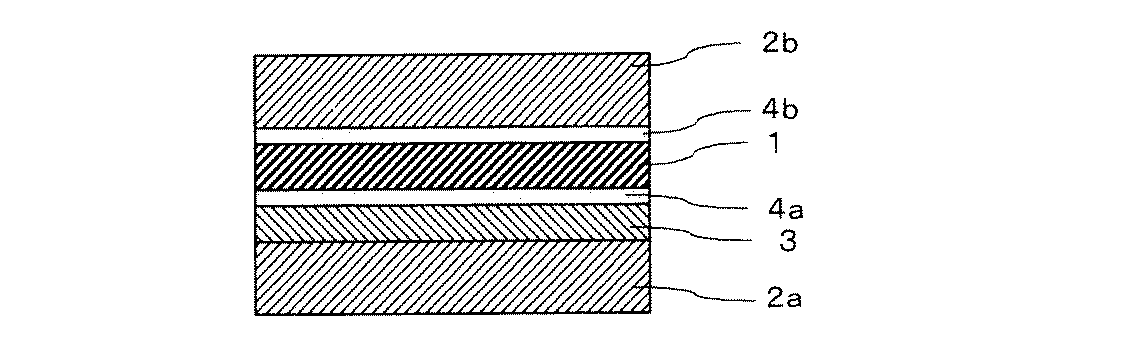
1 偏光子
2a 透明保護フィルム(環状オレフィン樹脂)
2b 透明保護フィルム
3 樹脂層
4a ポリビニルアルコール系接着剤層
4b 接着剤層
5 水性液
1
2b Transparent
Claims (9)
前記少なくとも一方の透明保護フィルムは、環状オレフィン系樹脂を主成分としており、かつ、
透明保護フィルムの偏光子に貼り合わせる面には、少なくとも1層以上の樹脂層およびポリビニルアルコール系接着剤層が順次に積層されており、
前記透明保護フィルムのポリビニルアルコール系接着剤層と偏光子とを貼り合わせる際に、貼り合わせ面に水性液を存在させることを特徴とする偏光板の製造方法。 A method for producing a polarizing plate in which a transparent protective film is provided on at least one surface of a polarizer,
The at least one transparent protective film is mainly composed of a cyclic olefin resin, and
On the surface to be bonded to the polarizer of the transparent protective film, at least one resin layer and a polyvinyl alcohol adhesive layer are sequentially laminated,
A method for producing a polarizing plate, wherein an aqueous liquid is present on a bonding surface when a polyvinyl alcohol adhesive layer of a transparent protective film and a polarizer are bonded together.
An image display device, wherein the polarizing plate according to claim 7 or the optical film according to claim 8 is used.
Priority Applications (6)
| Application Number | Priority Date | Filing Date | Title |
|---|---|---|---|
| JP2004208584A JP2005222013A (en) | 2004-01-06 | 2004-07-15 | Manufacturing method of polarizing plate, polarizing plate, optical film, and image display device |
| CNB2004101011866A CN100397111C (en) | 2004-01-06 | 2004-12-20 | Manufacturing method of polarizing plate, polarizing plate, optical film and image display device |
| US11/027,988 US20050147837A1 (en) | 2004-01-06 | 2005-01-04 | Fabrication method for polarizing plate, polarizing plate, optical film and image display |
| TW94100273A TW200535466A (en) | 2004-01-06 | 2005-01-05 | Fabrication method for polarizing plate, polarizing plate, optical film and image display |
| KR1020050001162A KR100882168B1 (en) | 2004-01-06 | 2005-01-06 | Manufacturing Method of Polarizing Plate, Polarizing Plate, Optical Film, and Image Display Device |
| US11/790,121 US20070193685A1 (en) | 2004-01-06 | 2007-04-24 | Fabrication method for polarizing plate, polarizing plate, opticl film and image |
Applications Claiming Priority (2)
| Application Number | Priority Date | Filing Date | Title |
|---|---|---|---|
| JP2004001291 | 2004-01-06 | ||
| JP2004208584A JP2005222013A (en) | 2004-01-06 | 2004-07-15 | Manufacturing method of polarizing plate, polarizing plate, optical film, and image display device |
Publications (1)
| Publication Number | Publication Date |
|---|---|
| JP2005222013A true JP2005222013A (en) | 2005-08-18 |
Family
ID=34712999
Family Applications (1)
| Application Number | Title | Priority Date | Filing Date |
|---|---|---|---|
| JP2004208584A Pending JP2005222013A (en) | 2004-01-06 | 2004-07-15 | Manufacturing method of polarizing plate, polarizing plate, optical film, and image display device |
Country Status (5)
| Country | Link |
|---|---|
| US (2) | US20050147837A1 (en) |
| JP (1) | JP2005222013A (en) |
| KR (1) | KR100882168B1 (en) |
| CN (1) | CN100397111C (en) |
| TW (1) | TW200535466A (en) |
Cited By (8)
| Publication number | Priority date | Publication date | Assignee | Title |
|---|---|---|---|---|
| JP2009053675A (en) * | 2007-07-30 | 2009-03-12 | Nippon Synthetic Chem Ind Co Ltd:The | Adhesive for polarizing plate, polarizing plate, and production method thereof |
| JP2009241283A (en) * | 2008-03-28 | 2009-10-22 | Nippon Zeon Co Ltd | Method for manufacturing laminated film and laminated film |
| JP2009242464A (en) * | 2008-03-28 | 2009-10-22 | Nippon Zeon Co Ltd | Method for manufacturing laminate film, and laminate film |
| JP2014112232A (en) * | 2008-11-25 | 2014-06-19 | Nitto Denko Corp | Manufacturing method of glass pane with polarizing plate, glass pane with polarizing plate, and liquid crystal cell with polarizing plate |
| JP2018139014A (en) * | 2018-05-31 | 2018-09-06 | 住友化学株式会社 | Polarizing plate and display |
| JP2020074036A (en) * | 2018-05-31 | 2020-05-14 | 住友化学株式会社 | Polarizing plate and display device |
| JP2020519732A (en) * | 2017-06-27 | 2020-07-02 | エルジー・ケム・リミテッド | Adhesive composition, protective film and polarizing plate containing adhesive layer containing the same, and image display device containing the same |
| JP2021105731A (en) * | 2020-01-27 | 2021-07-26 | 住友化学株式会社 | Polarizing plate and display |
Families Citing this family (17)
| Publication number | Priority date | Publication date | Assignee | Title |
|---|---|---|---|---|
| JP4059883B2 (en) * | 2002-12-20 | 2008-03-12 | 帝人株式会社 | Transparent conductive laminate, touch panel, and liquid crystal display with touch panel |
| JP2007075797A (en) * | 2005-09-16 | 2007-03-29 | Fujifilm Corp | Coating method, apparatus, optical film manufacturing method, and antireflection film manufacturing method |
| JP2007296726A (en) * | 2006-04-28 | 2007-11-15 | Jsr Corp | Method for producing optical film, method for producing optical film and stretched film |
| JP5049705B2 (en) * | 2006-11-16 | 2012-10-17 | 富士フイルム株式会社 | Transparent film, polarizing plate, and liquid crystal display device |
| JP2008129427A (en) * | 2006-11-22 | 2008-06-05 | Sumitomo Chemical Co Ltd | Polarizing plate and manufacturing method thereof |
| JP2009048157A (en) * | 2006-12-21 | 2009-03-05 | Fujifilm Corp | Liquid crystal display |
| JP2009063983A (en) * | 2006-12-21 | 2009-03-26 | Fujifilm Corp | Optical film and polarizing plate having the same |
| JP4751312B2 (en) * | 2006-12-22 | 2011-08-17 | 日東電工株式会社 | Optical film, polarizing plate, and image display device |
| KR101025466B1 (en) * | 2008-01-17 | 2011-04-04 | 닛토덴코 가부시키가이샤 | Polarizing plate, its manufacturing method, optical film, and image display apparatus |
| JP5348580B2 (en) * | 2008-01-31 | 2013-11-20 | 住友化学株式会社 | Manufacturing method of polarizing plate |
| JP2010026498A (en) * | 2008-06-17 | 2010-02-04 | Nitto Denko Corp | Polarizing plate and method of manufacturing the same |
| KR101718935B1 (en) * | 2010-01-11 | 2017-03-22 | 동우 화인켐 주식회사 | A polarizing plate |
| KR101260695B1 (en) * | 2010-08-13 | 2013-05-10 | 동우 화인켐 주식회사 | Adhesive composition for polarizer and polarizer using the same |
| JP5722255B2 (en) * | 2012-02-28 | 2015-05-20 | 住友化学株式会社 | Manufacturing method of polarizing plate |
| CN104610512A (en) * | 2015-01-19 | 2015-05-13 | 东华大学 | Preparation method of super-soft IPN (interpenetrating polymer network) pigment printing binder |
| JP6154054B2 (en) * | 2015-09-30 | 2017-06-28 | 日東電工株式会社 | Polarizing film with pressure-sensitive adhesive layer, method for producing the same, and image display device |
| US20200132901A1 (en) * | 2017-12-15 | 2020-04-30 | Huizhou China Star Optoelectronics Technology Co., Ltd. | Display module and polarizer thereof |
Family Cites Families (18)
| Publication number | Priority date | Publication date | Assignee | Title |
|---|---|---|---|---|
| US3581416A (en) * | 1966-12-09 | 1971-06-01 | Polaroid Corp | Tamper proof laminations having silver image |
| US3531351A (en) * | 1967-05-01 | 1970-09-29 | Polaroid Corp | Preparation of light-polarizing film |
| US3795516A (en) * | 1972-11-13 | 1974-03-05 | Eastman Kodak Co | Barrier layer for liquid crystal-containing elements |
| US4388375A (en) * | 1981-11-24 | 1983-06-14 | American Hoechst Corporation | Polyester based polarizer |
| US4396642A (en) * | 1981-11-24 | 1983-08-02 | American Hoechst Corporation | Hydrolytically stabilized polarizer |
| DE3931845A1 (en) * | 1989-09-23 | 1991-04-04 | Bayer Ag | QUICK CRYSTALIZING POLYURETHANE SYSTEMS |
| JP3132122B2 (en) * | 1992-02-05 | 2001-02-05 | 日本ゼオン株式会社 | Composite sheet |
| JP2001133628A (en) * | 1999-08-26 | 2001-05-18 | Nippon Mitsubishi Oil Corp | Method for producing polarization diffractive film |
| JP2001174637A (en) * | 1999-10-04 | 2001-06-29 | Sekisui Chem Co Ltd | Polarizing plate protective film and polarizing plate |
| KR100749302B1 (en) * | 1999-10-04 | 2007-08-14 | 세키스이가가쿠 고교가부시키가이샤 | Polarizer Protective Film and Polarizer |
| JP2001154020A (en) * | 1999-11-29 | 2001-06-08 | Nitto Denko Corp | Polarizing plate and optical member |
| DE10113084A1 (en) * | 2001-03-17 | 2002-09-19 | Leica Microsystems | Autofocus microscope system |
| US7136225B2 (en) * | 2001-05-10 | 2006-11-14 | Sumitomo Chemical Company, Limited | Polarizing plate and method for producing the same |
| JP2002350640A (en) * | 2001-05-28 | 2002-12-04 | Nitto Denko Corp | Method for producing protective film for polarizing plate, polarizing plate, optical film using polarizing plate, and liquid crystal display device |
| KR100822247B1 (en) * | 2002-04-01 | 2008-04-16 | 닛토덴코 가부시키가이샤 | Optical film and image display system |
| KR20030079705A (en) * | 2002-04-01 | 2003-10-10 | 닛토덴코 가부시키가이샤 | Optical film and display system |
| JP2005010760A (en) * | 2003-05-26 | 2005-01-13 | Nitto Denko Corp | Adhesive for polarizing plate, polarizing plate, method for producing the same, optical film, and image display device |
| US7749348B2 (en) * | 2003-09-30 | 2010-07-06 | Nitto Denko Corporation | Method for manufacturing polarizing plate, polarizing plate, optical film and image viewing display |
-
2004
- 2004-07-15 JP JP2004208584A patent/JP2005222013A/en active Pending
- 2004-12-20 CN CNB2004101011866A patent/CN100397111C/en not_active Expired - Fee Related
-
2005
- 2005-01-04 US US11/027,988 patent/US20050147837A1/en not_active Abandoned
- 2005-01-05 TW TW94100273A patent/TW200535466A/en unknown
- 2005-01-06 KR KR1020050001162A patent/KR100882168B1/en not_active Expired - Fee Related
-
2007
- 2007-04-24 US US11/790,121 patent/US20070193685A1/en not_active Abandoned
Cited By (9)
| Publication number | Priority date | Publication date | Assignee | Title |
|---|---|---|---|---|
| JP2009053675A (en) * | 2007-07-30 | 2009-03-12 | Nippon Synthetic Chem Ind Co Ltd:The | Adhesive for polarizing plate, polarizing plate, and production method thereof |
| JP2009241283A (en) * | 2008-03-28 | 2009-10-22 | Nippon Zeon Co Ltd | Method for manufacturing laminated film and laminated film |
| JP2009242464A (en) * | 2008-03-28 | 2009-10-22 | Nippon Zeon Co Ltd | Method for manufacturing laminate film, and laminate film |
| JP2014112232A (en) * | 2008-11-25 | 2014-06-19 | Nitto Denko Corp | Manufacturing method of glass pane with polarizing plate, glass pane with polarizing plate, and liquid crystal cell with polarizing plate |
| JP2020519732A (en) * | 2017-06-27 | 2020-07-02 | エルジー・ケム・リミテッド | Adhesive composition, protective film and polarizing plate containing adhesive layer containing the same, and image display device containing the same |
| JP7050815B2 (en) | 2017-06-27 | 2022-04-08 | 杉金光電(蘇州)有限公司 | An adhesive composition, a protective film and a polarizing plate including an adhesive layer containing the adhesive composition, and an image display device including the same. |
| JP2018139014A (en) * | 2018-05-31 | 2018-09-06 | 住友化学株式会社 | Polarizing plate and display |
| JP2020074036A (en) * | 2018-05-31 | 2020-05-14 | 住友化学株式会社 | Polarizing plate and display device |
| JP2021105731A (en) * | 2020-01-27 | 2021-07-26 | 住友化学株式会社 | Polarizing plate and display |
Also Published As
| Publication number | Publication date |
|---|---|
| US20070193685A1 (en) | 2007-08-23 |
| US20050147837A1 (en) | 2005-07-07 |
| CN100397111C (en) | 2008-06-25 |
| KR100882168B1 (en) | 2009-02-06 |
| CN1637444A (en) | 2005-07-13 |
| TW200535466A (en) | 2005-11-01 |
| KR20050072696A (en) | 2005-07-12 |
Similar Documents
| Publication | Publication Date | Title |
|---|---|---|
| JP2005222013A (en) | Manufacturing method of polarizing plate, polarizing plate, optical film, and image display device | |
| JP4335901B2 (en) | Manufacturing method of polarizing plate | |
| JP4686512B2 (en) | Polarizing plate, manufacturing method thereof, optical film, and image display device | |
| JP4603572B2 (en) | Adhesive for polarizing plate, polarizing plate, method for producing the same, optical film, and image display device | |
| JP4301558B2 (en) | Adhesive for polarizing plate, polarizing plate, method for producing the same, optical film, and image display device | |
| JP2005010760A (en) | Adhesive for polarizing plate, polarizing plate, method for producing the same, optical film, and image display device | |
| JP4644661B2 (en) | Polarizing plate and image display device | |
| JP2009093074A (en) | Manufacturing method of polarizing plate, polarizing plate, optical film, and image display device | |
| JP4402096B2 (en) | Polarizing plate, manufacturing method thereof, optical film, and image display device | |
| CN101187712A (en) | Manufacturing method of polarizing plate, polarizing plate, optical film, and image display device | |
| KR100882169B1 (en) | Manufacturing method of polarizing plate, polarizing plate, optical film, and image display apparatus | |
| JP4043263B2 (en) | Manufacturing method of polarizer, polarizer, polarizing plate, and image display device | |
| JP2008102274A (en) | Polarizer, polarizing plate, optical film, and image display device | |
| KR20070097518A (en) | Polarizing plate, its manufacturing method, optical film, and image display apparatus using the same | |
| JP4644660B2 (en) | Polarizing plate and image display device | |
| JP4920876B2 (en) | Manufacturing method of polarizing plate, polarizing plate, optical film, and image display device | |
| JP2005017707A (en) | Antireflection film, polarizing plate, optical element and image display device | |
| JP4197239B2 (en) | Polarizer, production method thereof, polarizing plate, optical film, and image display device | |
| JP4803833B2 (en) | Manufacturing method of polarizing plate, polarizing plate, optical film, and image display device | |
| JP4594290B2 (en) | Adhesive for polarizing plate, polarizing plate, method for producing the same, optical film, and image display device | |
| JP2008250326A (en) | Manufacturing method of polarizer and wet stretching apparatus used therefor | |
| JP5013496B2 (en) | Polarizing plate, manufacturing method of polarizing plate, optical film, and image display device | |
| JP2004177785A (en) | Adhesive elliptically polarizing plate and image display device | |
| JP2006058437A (en) | Manufacturing method of polarizing plate, polarizing plate, optical film, and image display device | |
| JP2007041254A (en) | Polarizer, manufacturing method thereof, polarizing plate, manufacturing method thereof, optical film, and image display device |
Legal Events
| Date | Code | Title | Description |
|---|---|---|---|
| A621 | Written request for application examination |
Free format text: JAPANESE INTERMEDIATE CODE: A621 Effective date: 20061106 |
|
| A131 | Notification of reasons for refusal |
Free format text: JAPANESE INTERMEDIATE CODE: A131 Effective date: 20090804 |
|
| A521 | Written amendment |
Free format text: JAPANESE INTERMEDIATE CODE: A523 Effective date: 20091002 |
|
| RD03 | Notification of appointment of power of attorney |
Free format text: JAPANESE INTERMEDIATE CODE: A7423 Effective date: 20091002 |
|
| A02 | Decision of refusal |
Free format text: JAPANESE INTERMEDIATE CODE: A02 Effective date: 20100105 |