JP2005225736A - Rotary kiln and method for treating flammable waste using the same - Google Patents
Rotary kiln and method for treating flammable waste using the same Download PDFInfo
- Publication number
- JP2005225736A JP2005225736A JP2004037953A JP2004037953A JP2005225736A JP 2005225736 A JP2005225736 A JP 2005225736A JP 2004037953 A JP2004037953 A JP 2004037953A JP 2004037953 A JP2004037953 A JP 2004037953A JP 2005225736 A JP2005225736 A JP 2005225736A
- Authority
- JP
- Japan
- Prior art keywords
- combustible waste
- main fuel
- rotary kiln
- waste
- burner
- Prior art date
- Legal status (The legal status is an assumption and is not a legal conclusion. Google has not performed a legal analysis and makes no representation as to the accuracy of the status listed.)
- Granted
Links
Images

Classifications
-
- Y—GENERAL TAGGING OF NEW TECHNOLOGICAL DEVELOPMENTS; GENERAL TAGGING OF CROSS-SECTIONAL TECHNOLOGIES SPANNING OVER SEVERAL SECTIONS OF THE IPC; TECHNICAL SUBJECTS COVERED BY FORMER USPC CROSS-REFERENCE ART COLLECTIONS [XRACs] AND DIGESTS
- Y02—TECHNOLOGIES OR APPLICATIONS FOR MITIGATION OR ADAPTATION AGAINST CLIMATE CHANGE
- Y02P—CLIMATE CHANGE MITIGATION TECHNOLOGIES IN THE PRODUCTION OR PROCESSING OF GOODS
- Y02P40/00—Technologies relating to the processing of minerals
- Y02P40/10—Production of cement, e.g. improving or optimising the production methods; Cement grinding
- Y02P40/125—Fuels from renewable energy sources, e.g. waste or biomass
Landscapes
- Gasification And Melting Of Waste (AREA)
- Curing Cements, Concrete, And Artificial Stone (AREA)
Abstract
【課題】投入した可燃性廃棄物を効率良く燃焼させる。
【解決手段】主燃料バーナ10及び可燃性廃棄物燃焼バーナ11を備えたセメントクリンカ製造用のロータリーキルン1において、可燃性廃棄物燃焼バーナ11を主燃料バーナ10の下側に配置し、この可燃性廃棄物燃焼バーナ11による可燃性廃棄物Sの吹出方向を、主燃料バーナ11の胴部、または、主燃料バーナ11の火炎Fに向かうように傾け、可燃性廃棄物の投入箇所を、主燃料バーナの先端10aから前方に1m、後方に2mの範囲に設定した。
【選択図】図1An object of the present invention is to efficiently burn combustible waste that has been input.
In a rotary kiln (1) for producing cement clinker having a main fuel burner (10) and a combustible waste combustion burner (11), a combustible waste combustion burner (11) is disposed below the main fuel burner (10), and the combustibility is increased. The direction in which the combustible waste S is blown out by the waste combustion burner 11 is tilted toward the trunk of the main fuel burner 11 or the flame F of the main fuel burner 11, and the injection point of the combustible waste is changed to the main fuel. The range was set to 1 m forward and 2 m backward from the tip 10 a of the burner.
[Selection] Figure 1
Description
本発明は、廃プラスチック等の可燃性廃棄物を補助燃料として用いるロータリーキルン及びこれを用いた可燃性廃棄物の処理方法に関するものである。 The present invention relates to a rotary kiln using flammable waste such as waste plastic as an auxiliary fuel and a method for treating flammable waste using the rotary kiln.
産業廃棄物の発生量は年々増加の一途をたどっている。その処理方法としては埋め立て処理、焼却処理等が知られている。しかし、埋め立て場の確保が難しくなってきていることから、焼却処理が注目を浴びてきている。かかる産業廃棄物の中でも廃プラスチックやごみ固体化燃料(RDF)等の可燃性廃棄物は、焼却によって大きな熱量を発生するため、その燃焼によって生じる熱量を有効に利用すべく、各種の燃焼炉の燃料として利用されつつある。 The amount of industrial waste generated has been increasing year by year. As the processing method, landfill processing, incineration processing and the like are known. However, incineration has attracted attention because it has become difficult to secure a landfill. Among such industrial wastes, combustible wastes such as waste plastics and solid waste fuel (RDF) generate a large amount of heat by incineration. Therefore, in order to effectively use the amount of heat generated by the combustion, various combustion furnaces It is being used as fuel.
例えば、廃プラスチック等の可燃性廃棄物を燃料として利用する方法として、その破砕品をセメント焼成設備のロータリーキルンの窯前部からロータリーキルン内に空気流に乗せて吹き込んで燃焼させ、主燃料として使用する微粉炭の使用量を削減する技術が以前より知られている。 For example, as a method of using flammable waste such as waste plastic as fuel, the crushed product is blown into an air flow from the front of the kiln of the rotary kiln of the cement firing equipment and burned to be used as the main fuel. Techniques for reducing the amount of pulverized coal used have been known for some time.
特許文献1には、主燃料バーナの上側に可燃性廃棄物燃焼バーナを設けて、可燃性廃棄物を主燃料による火炎中に落下するように投入することにより、ロータリーキルン壁への着地前に空間燃焼を完了させるロータリーキルンが開示されている。また、特許文献2には、キルンの中心から降ろした鉛直線から回転方向に110度の範囲に可燃性廃棄物燃焼バーナを設け、可燃性廃棄物をクリンカ上に降下するように投入して、クリンカからの高熱と酸素の多い二次空気により、可燃性廃棄物を効率良く燃焼させる技術が開示されている。
In
ところが、上記従来技術においては、投入した可燃性廃棄物の拡散の度合いが低いために、必ずしも可燃性廃棄物を効率良く燃焼させることができないという問題があった。 However, in the above-described conventional technology, there is a problem that the combustible waste cannot be efficiently burned because the degree of diffusion of the combustible waste that has been input is low.
本発明は、上記事情を考慮し、投入した可燃性廃棄物を効率良く燃焼させることのできるロータリーキルンおよびこれを用いた可燃性廃棄物の処理方法を提供することを目的としている。 In view of the above circumstances, an object of the present invention is to provide a rotary kiln capable of efficiently burning combustible waste that has been input and a method for treating combustible waste using the rotary kiln.
請求項1の発明のロータリーキルンは、主燃料バーナ及び可燃性廃棄物燃焼バーナを備えたセメントクリンカ製造用のロータリーキルンにおいて、前記可燃性廃棄物燃焼バーナを主燃料バーナの下側に配置し、この可燃性廃棄物燃焼バーナによる可燃性廃棄物の吹出方向を、主燃料バーナの胴部、または、主燃料バーナの火炎に向かうように傾けたことを特徴とする。
The rotary kiln of the invention of
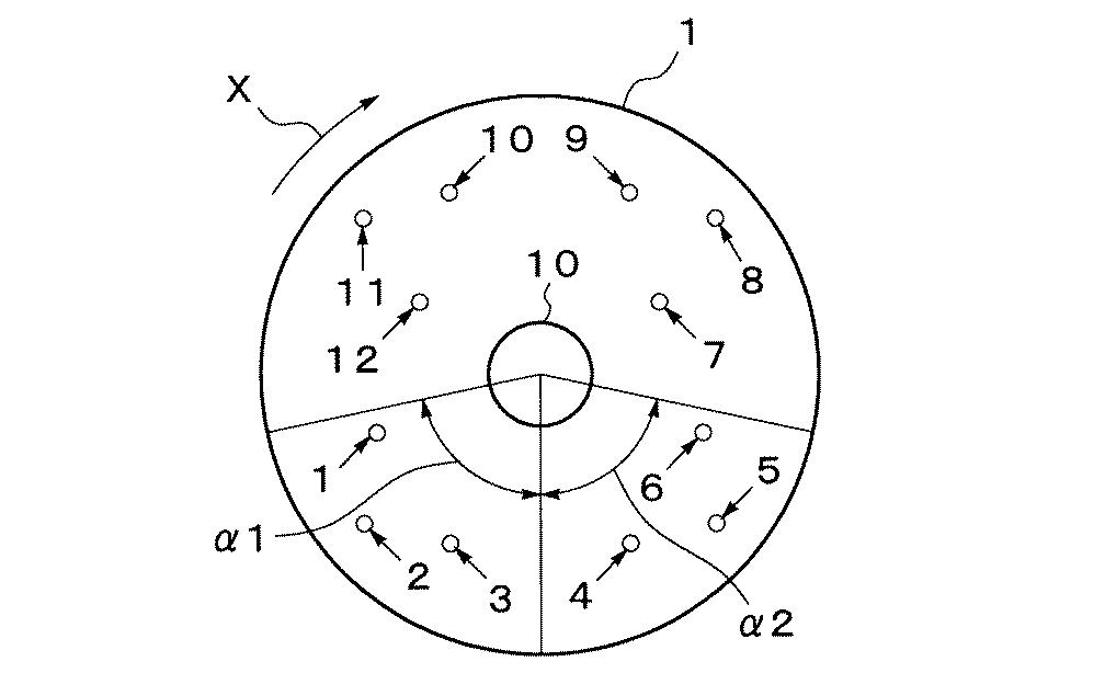
請求項2の発明のロータリーキルンは、請求項1において、前記可燃性廃棄物燃焼バーナを、キルンの回転中心から下ろした鉛直線から、回転方向あるいはその逆方向に80度の範囲に設けたことを特徴とする。 A rotary kiln according to a second aspect of the present invention is the rotary kiln according to the first aspect, wherein the combustible waste combustion burner is provided within a range of 80 degrees in the rotational direction or the opposite direction from the vertical line drawn from the rotational center of the kiln. Features.
請求項3の発明の可燃性廃棄物の処理方法は、セメントクリンカ製造用のロータリーキルン内を加熱するために、主燃料バーナに加えて設けられた可燃性廃棄物燃焼バーナによる可燃性廃棄物の処理方法において、前記可燃性廃棄物燃焼バーナから、主燃料バーナの胴部または主燃料バーナの火炎に向けて可燃性廃棄物を投入することを特徴とする。 According to a third aspect of the present invention, there is provided a method for treating flammable waste, comprising: a flammable waste combustion burner provided in addition to a main fuel burner for heating a rotary kiln for producing cement clinker. In the method, the combustible waste is injected from the combustible waste combustion burner toward the trunk of the main fuel burner or the flame of the main fuel burner.
請求項4の発明の可燃性廃棄物の処理方法は、請求項3において、前記可燃性廃棄物の投入箇所を、主燃料バーナの先端から前方に1m、後方に2mの範囲に設定したことを特徴とする。 The method for treating flammable waste according to claim 4 is the method according to claim 3, wherein the place where the flammable waste is introduced is set in a range of 1 m forward from the tip of the main fuel burner and 2 m backward. Features.
請求項5の発明の可燃性廃棄物の処理方法は、請求項3または4において、前記可燃性廃棄物として廃プラスチックを投入する場合は、主燃料バーナの火炎に向けて投入することを特徴とする。
The method for treating combustible waste according to
請求項6の発明の可燃性廃棄物の処理方法は、請求項3または4において、前記可燃性廃棄物として、木屑、肉骨粉、魚粉の少なくともいずれかを投入する場合は、主燃料バーナの胴部にぶつかるように投入することを特徴とする。 The method for treating flammable waste according to the invention of claim 6 is the body of the main fuel burner according to claim 3 or 4, wherein at least one of wood chips, meat-and-bone meal and fish meal is used as the flammable waste. It is characterized by being thrown in so as to hit the part.
請求項7の発明の可燃性廃棄物の処理方法は、請求項3〜6のいずれかにおいて、前記可燃性廃棄物の投入量を、熱量換算で、セメント製造に用いられる燃料全体の熱量に対して1%以上50%以下とすることを特徴とする。
The method for treating flammable waste according to
請求項8の発明の可燃性廃棄物の処理方法は、請求項3〜7のいずれかにおいて、前記可燃性廃棄物の粒径を50mm以下に調整した上で投入することを特徴とする。 The method for treating flammable waste according to claim 8 is characterized in that in any one of claims 3 to 7, the flammable waste is charged after the particle size of the combustible waste is adjusted to 50 mm or less.
本発明によれば、可燃性廃棄物を広く拡散させながらクリンカ上に降下させることができる。つまり、主燃料バーナの胴部に可燃性廃棄物をぶつけたり、主燃料バーナの火炎に向けて可燃性廃棄物を吹き出したりすることにより、可燃性廃棄物を広く散らばらせながら、高温のクリンカ上に降下させることができ、燃焼効率を高めることができる。特に可燃性廃棄物の高温燃焼作用によってフリーライムを下げることができるため、最終的に強度の高いセメントを得ることができ、多量の可燃性廃棄物を投入しても、セメントの品質を低下させることがなくなる。また、可燃性廃棄物の焼却灰はセメントの製造原料の一部として有効に利用できる。 According to the present invention, combustible waste can be lowered onto the clinker while widely diffusing. In other words, by burning flammable waste against the body of the main fuel burner or blowing out flammable waste toward the flame of the main fuel burner, It can be lowered and combustion efficiency can be increased. In particular, because high-temperature combustion action of combustible waste can reduce free lime, it is possible to finally obtain a high-strength cement, and even if a large amount of combustible waste is added, the quality of the cement is lowered. Nothing will happen. Incinerated ash of combustible waste can be effectively used as part of the raw material for producing cement.
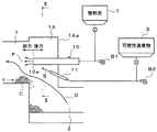
以下、本発明の実施形態を図面に基づいて説明する。図1は本発明のロータリーキルンの概略構成図、図2は図1のII−II線に沿う断面図である。 Hereinafter, embodiments of the present invention will be described with reference to the drawings. FIG. 1 is a schematic configuration diagram of a rotary kiln of the present invention, and FIG. 2 is a cross-sectional view taken along line II-II in FIG.
図1において、被焼成物であるセメント原料は、ロータリーキルン1内の上流端である窯尻部側(図中左側)から投入され、ロータリーキルン1内を矢印Yのように、下流側である窯前部1A側(図中右側)に移動しながら焼成され、焼成されたセメントクリンカCは、窯前部1Aの下部に接続されたクリンカクーラー2に落ちて、さらに下流側に移動しながら二次空気Dによって冷却される。この二次空気Dは、クリンカクーラー2においてセメントクリンカCから熱を吸収して高温になると共に、窯前部1Aを通ってロータリーキルン1内を上流側に流れる。
In FIG. 1, a cement raw material to be fired is charged from the kiln bottom side (left side in the figure) which is the upstream end in the
ロータリーキルン1の下流端である窯前部1Aの端壁1Aaには、主燃料である微粉炭TをブロワーB1から供給される一次空気と共にロータリーキルン1内に吹き込む円筒形状の主燃料バーナ10が設けられている。この主燃料バーナ10は、主燃料である微粉炭Tを一次空気と共に、窯前部1Aから窯尻部の方向に向かって吹き出して、微粉炭Tを燃焼させるものである。さらに、主燃料バーナ10は、図2に示すように、窯前部1Aの端壁1Aaにおけるロータリーキルン1の回転中心に対応する位置に配置されており、微粉炭Tを該ロータリーキルン1の回転中心軸に沿って吹き出すようになっている。
A cylindrical
また、窯前部1Aの端壁1Aaには、図1に示すように、廃プラスチックやごみ固体化燃料(RDF)等の可燃性廃棄物Sの破砕品を補助燃料用のブロワーB2から供給される補助一次空気と共にロータリーキルン1内に吹き込む円筒形状の可燃性廃棄物燃焼バーナ11が、主燃料バーナ10の下側に位置させて配置されている。この場合、可燃性廃棄物燃焼バーナ11は、可燃性廃棄物Sの吹出方向が、主燃料バーナ10の胴部、または、主燃料バーナ10の前方に形成される火炎Fを指向するように傾けて設置されている。また、可燃性廃棄物燃焼バーナ11は、図2に示すように、キルンの回転中心から下ろした鉛直線から、回転方向(矢印X方向)あるいはその逆方向に80度の範囲(角度α1、α2の範囲)に設けられている。
Further, as shown in FIG. 1, a crushed product of combustible waste S such as waste plastic and waste solidified fuel (RDF) is supplied to the end wall 1Aa of the front part 1A of the kiln from a blower B2 for auxiliary fuel. A cylindrical flammable
ここで、可燃性廃棄物燃焼バーナ11による可燃性廃棄物Sの投入箇所は、主燃料バーナ10の先端10aから前方に1m、後方に2mの範囲に設定されている。例えば、可燃性廃棄物Sとして廃プラスチック等の高温で軟化するものを投入する場合には、主燃料バーナ10の先端10aから前方に1m以内の火炎Fに向けて当該火炎Fにぶつかるように可燃性廃棄物Sを投入すべく、可燃性廃棄物燃焼バーナ11の吹出角度(傾角)が設定されている。また、可燃性廃棄物Sとして木屑、肉骨粉、魚粉の少なくともいずれか(木屑、肉骨粉、魚粉のうち1種以上)を投入する場合には、主燃料バーナ11の胴部に向けて当該胴部にぶつかるように可燃性廃棄物Sを投入すべく、可燃性廃棄物燃焼バーナ11の吹出角度(傾角)が設定されている。
Here, the place where the combustible waste S is charged by the combustible
次に、本発明の可燃性廃棄物の処理方法を上記ロータリーキルン1の作用効果と共に説明する。
セメントクリンカCを製造するに当たり、主燃料用のブロワーB1から供給した一次空気を、微粉炭Tと共に主燃料バーナ10から吹き出して燃焼させる。同時に、補助燃料用のブロワーB2から供給される補助一次空気を、例えば、廃プラスチックを細かく砕いた可燃性廃棄物Sと共に可燃性廃棄物燃焼バーナ11から吹き出して燃焼させる。
Next, the processing method of the combustible waste of this invention is demonstrated with the effect of the said
In manufacturing the cement clinker C, the primary air supplied from the blower B1 for main fuel is blown out from the
そのように可燃性廃棄物Sを投入した場合、可燃性廃棄物Sは、主燃料バーナ10の火炎Fからの輻射熱や、高温のセメントクリンカCからの輻射熱や、クリンカクーラー2においてセメントクリンカCから熱を吸収して高温となった二次空気Dからの熱や、その他からの熱を受けて高温となり、該二次空気Dの高温雰囲気中で燃焼を開始することになる。
When the combustible waste S is introduced in such a manner, the combustible waste S is generated from the radiant heat from the flame F of the
その際、可燃性廃棄物Sを広く拡散させながら、セメントクリンカC上に降下させることができる。つまり、主燃料バーナ10の胴部に向けて当該胴部に可燃性廃棄物Sを当てるべく可燃性廃棄物Sを吹き出したり、主燃料バーナ10の火炎Fに向けて当該火炎Fに当てるべく可燃性廃棄物Sを吹き出したりすることにより、可燃性廃棄物Sが広く散らばりながら、火炎F等から効率よく熱を受けて燃焼すると共に高温のクリンカC上に降下させることができる。
At that time, the combustible waste S can be lowered onto the cement clinker C while being widely diffused. That is, the combustible waste S is blown out toward the trunk portion of the
ここで、ロータリーキルン1内では、セメントクリンカCが周方向に回転しながら掻き上げられてはその上端部から崩れ落ちることを繰り返す状態になっている。このため、可燃性廃棄物燃焼バーナ11から吹き出し後、完全に燃焼するに至らなかった可燃性廃棄物Sは、掻き上げられてはその上端部から崩れ落ちる約1400℃のセメントクリンカC上等に分散して降下し、セメントクリンカCから極めて効率良く熱を受けると共に、ロータリーキルン1内に供給される二次空気とも極めて効率よく混合されることになる。従って、可燃性廃棄物Sを極めて効率よく燃焼させることができる。また、この燃焼効率の向上による高温の作用によってフリーライムが下がるため、最終的に強度の高いセメントを得ることができる。また、可燃性廃棄物Sの焼却灰は、セメントの製造のために必要な原料の一部として有効利用される。
Here, in the
なお、可燃性廃棄物Sの投入量を、熱量換算で、セメント製造に用いられる燃料全体の熱量に対して1%以上50%以下とするのが望ましい。そうすることで、セメントの品質を低下させるおそれがなくなるからである。好ましくは、30%以下とするのがよい。また、可燃性廃棄物Sは、粒径を50mm以下に調整した上で投入するのがよい。 In addition, it is desirable that the input amount of the combustible waste S is 1% or more and 50% or less with respect to the heat amount of the whole fuel used for cement production in terms of heat amount. By doing so, there is no risk of lowering the quality of the cement. Preferably, it should be 30% or less. In addition, the combustible waste S is preferably introduced after the particle size is adjusted to 50 mm or less.
実施例1では、可燃性廃棄物Sの投入点(主燃料バーナの先端10aからの距離)を変化させた場合のセメントクリンカ中のフリーライム(f.CaO)の発生率について調べた。その結果を表1に示す。投入条件として、可燃性廃棄物である木材チップ(粒径0〜50mm)を、図2の3番の箇所の可燃性廃棄物燃焼バーナ11から投入した。投入量は12.5kg/t-cli(クリンカ1トン当たりの可燃性廃棄物の投入重量をkgで示した単位)である。f.CaOが多いということは、燃焼効率が悪いことを意味すると共に、セメントの製品としても不適切なものとなる。特に、f.CaOが1.0%以上の場合は製品にできない。そこで、投入可能なポイントは、主燃料バーナ10の先端10aから前方へ1.0m、後方へ2.0mの範囲がよいことが分かった。
In Example 1, the occurrence rate of free lime (f.CaO) in the cement clinker when the input point of the combustible waste S (distance from the tip 10a of the main fuel burner) was changed was examined. The results are shown in Table 1. As input conditions, wood chips (particle size 0 to 50 mm), which is combustible waste, were input from the combustible
実施例2では、可燃性廃棄物Sとしてプラスチックを投入した場合の、可燃性廃棄物Sの投入点(主燃料バーナの先端10aからの距離)と、セメントクリンカ中のフリーライム(f.CaO)の発生率との関係について調べた。その結果を表2に示す。投入条件として、可燃性廃棄物であるプラスチック(粒径0〜20mm)を、図2の3番の箇所の可燃性廃棄物燃焼バーナ11から投入した。投入量は12.5kg/t-cliである。f.CaOが多いということは、燃焼効率が悪いということであり、1.0%以上は製品にできない。そこで、プラスチックを投入する場合の投入可能なポイントは、主燃料バーナ10の先端10aから前方へ1.0mの範囲がよいことが分かった。
In Example 2, when plastic is used as the combustible waste S, the input point of the combustible waste S (distance from the tip 10a of the main fuel burner) and the free lime (f.CaO) in the cement clinker We investigated the relationship with the incidence. The results are shown in Table 2. As an input condition, a combustible waste plastic (particle size: 0 to 20 mm) was supplied from the combustible
実施例3では、可燃性廃棄物燃焼バーナ11の位置と、セメントクリンカ中のフリーライム(f.CaO)の発生率との関係について調べた。その結果を表3に示す。投入条件として、可燃性廃棄物である木材チップ(粒径0.1〜50mm)を、図2の1〜12番の各箇所の可燃性廃棄物燃焼バーナ11から、主燃料バーナ10の先端10aから後方1.0mのポイントを狙って投入した。投入量は12.5kg/t-cliである。f.CaOが多いということは、燃焼効率が悪いということであり、1.0%以上は製品にできない。そこで、可燃性廃棄物燃焼バーナ11を設ける位置は、1〜6番が最適であり、7〜12番は不適切であることが分かった。つまり、キルンの中心から降ろした鉛直線から回転方向あるいはその逆方向に80度の範囲に可燃性廃棄物燃焼バーナ11を設けるのがよいことが分かった。
In Example 3, the relationship between the position of the combustible
実施例4では、クリンカ製造に関わる熱量全体に対する、副バーナ(可燃性廃棄物燃焼バーナ11)からの投入可燃性廃棄物の熱量割合と、セメントクリンカ中のフリーライム(f.CaO)の発生率との関係について調べた。その結果を表4に示す。投入条件として、可燃性廃棄物である木材チップ(粒径0〜50mm)を、図2の3番の可燃性廃棄物燃焼バーナ11から、主燃料バーナ10の先端10aの後方1.0mのポイントを狙って投入した。f.CaOが多いということは、燃焼効率が悪いということであり、1.0%以上は製品にできない。そこで、可燃性廃棄物の投入量は、熱量換算で、セメント製造に用いられる燃料全体の熱量に対して1%以上50%以下とするのがよく、特に30%以下とするのがよいことが分かった。
In Example 4, the calorific proportion of the combustible waste introduced from the secondary burner (combustible waste combustion burner 11) with respect to the total calorific value related to clinker production, and the generation rate of free lime (f.CaO) in the cement clinker We investigated the relationship with. The results are shown in Table 4. As a charging condition, a wood chip (particle size of 0 to 50 mm), which is combustible waste, is pointed 1.0 m behind the tip 10a of the
実施例5では、投入する可燃性廃棄物Sの粒径を変化させた場合の、セメントクリンカ中のフリーライム(f.CaO)の発生率について調べた。その結果を表5に示す。投入条件として、可燃性廃棄物である木材チップを粒径を段階的に異ならせて、図2の3番の可燃性廃棄物燃焼バーナ11から、主燃料バーナ10の先端10aの後方1.0mのポイントを狙って投入した。f.CaOが多いということは、燃焼効率が悪いということであり、1.0%以上は製品にできない。そこで、投入する可燃性廃棄物の粒径は、50mm以下とするのがよいことが分かった。なお、プラスチックや木材等の可燃性廃棄物を破砕する破砕装置の性能上、投入する可燃性廃棄物の粒径は、ほぼ0.1mm以上となる。
In Example 5, the occurrence rate of free lime (f.CaO) in the cement clinker when the particle size of the combustible waste S to be input was changed was examined. The results are shown in Table 5. As an input condition, the wood chip, which is a combustible waste, is gradually changed in particle size, and from the third combustible
1 ロータリーキルン
10 主燃料バーナ
11 可燃性廃棄物燃焼バーナ
S 可燃性廃棄物
F 火炎
1
Claims (8)
Priority Applications (1)
| Application Number | Priority Date | Filing Date | Title |
|---|---|---|---|
| JP2004037953A JP4947249B2 (en) | 2004-02-16 | 2004-02-16 | Method for treating combustible waste using a rotary kiln |
Applications Claiming Priority (1)
| Application Number | Priority Date | Filing Date | Title |
|---|---|---|---|
| JP2004037953A JP4947249B2 (en) | 2004-02-16 | 2004-02-16 | Method for treating combustible waste using a rotary kiln |
Publications (2)
| Publication Number | Publication Date |
|---|---|
| JP2005225736A true JP2005225736A (en) | 2005-08-25 |
| JP4947249B2 JP4947249B2 (en) | 2012-06-06 |
Family
ID=35000743
Family Applications (1)
| Application Number | Title | Priority Date | Filing Date |
|---|---|---|---|
| JP2004037953A Expired - Fee Related JP4947249B2 (en) | 2004-02-16 | 2004-02-16 | Method for treating combustible waste using a rotary kiln |
Country Status (1)
| Country | Link |
|---|---|
| JP (1) | JP4947249B2 (en) |
Cited By (3)
| Publication number | Priority date | Publication date | Assignee | Title |
|---|---|---|---|---|
| WO2008050678A1 (en) * | 2006-10-24 | 2008-05-02 | Taiheiyo Cement Corporation | Method for removing lead from cement kiln |
| JP2009165919A (en) * | 2008-01-11 | 2009-07-30 | Taiheiyo Cement Corp | Processing system for combustible waste containing metals and chlorine |
| JP2023083939A (en) * | 2021-12-06 | 2023-06-16 | 太平洋セメント株式会社 | Combustible waste injection device and its operation method |
Citations (18)
| Publication number | Priority date | Publication date | Assignee | Title |
|---|---|---|---|---|
| JPS5181824A (en) * | 1975-01-14 | 1976-07-17 | Daido Oxygen | |
| JPS5717867B2 (en) * | 1972-07-27 | 1982-04-13 | ||
| JPH0771728A (en) * | 1993-09-03 | 1995-03-17 | Mitsui Eng & Shipbuild Co Ltd | Burner |
| JPH08283053A (en) * | 1995-04-14 | 1996-10-29 | Yoshizawa Sekkai Kogyo Kk | Combustion method of waste plastic in rotary kiln |
| JP2000319049A (en) * | 1999-04-30 | 2000-11-21 | Taiheiyo Cement Corp | Production of cement clinker |
| JP2001012705A (en) * | 1999-06-30 | 2001-01-19 | Sumitomo Osaka Cement Co Ltd | Fuel combustor apparatus and combustion method for cement rotary kiln |
| JP2001064049A (en) * | 1999-07-02 | 2001-03-13 | L'air Liquide | Combustion process applicable to production of cement |
| JP2001114539A (en) * | 1999-10-18 | 2001-04-24 | Sumitomo Osaka Cement Co Ltd | Apparatus for and method of burning fuel for cement rotary kiln |
| JP2001120950A (en) * | 1999-10-25 | 2001-05-08 | Taiheiyo Cement Corp | Method for decreasing nitrogen oxide in cement raw material firing device |
| JP2002029791A (en) * | 2000-07-07 | 2002-01-29 | Taiheiyo Cement Corp | Firing process of cement clinker raw material |
| JP2003083519A (en) * | 2001-09-10 | 2003-03-19 | Mitsubishi Materials Corp | Rotary kiln fuel combustion method and combustion apparatus |
| JP2003090522A (en) * | 2001-09-20 | 2003-03-28 | Mitsubishi Materials Corp | Injectable structure of combustible waste into rotary kiln |
| JP2003106771A (en) * | 2001-09-27 | 2003-04-09 | Mitsubishi Materials Corp | Rotary kiln and method for treating combustible waste using the same |
| JP2003106508A (en) * | 2001-09-28 | 2003-04-09 | Mitsubishi Materials Corp | Injectable structure of combustible waste into rotary kiln |
| JP2003130549A (en) * | 2001-10-29 | 2003-05-08 | Mitsubishi Materials Corp | Rotary kiln |
| JP2003201489A (en) * | 2001-11-02 | 2003-07-18 | Maejima Fumio | Solid fuel material of powdered flesh and bone and method for producing the same |
| JP2003201481A (en) * | 2002-01-08 | 2003-07-18 | Masayuki Matsui | Carbonization furnace |
| JP2003275607A (en) * | 2002-03-22 | 2003-09-30 | Miike Iron Works Co Ltd | Crusher |
-
2004
- 2004-02-16 JP JP2004037953A patent/JP4947249B2/en not_active Expired - Fee Related
Patent Citations (18)
| Publication number | Priority date | Publication date | Assignee | Title |
|---|---|---|---|---|
| JPS5717867B2 (en) * | 1972-07-27 | 1982-04-13 | ||
| JPS5181824A (en) * | 1975-01-14 | 1976-07-17 | Daido Oxygen | |
| JPH0771728A (en) * | 1993-09-03 | 1995-03-17 | Mitsui Eng & Shipbuild Co Ltd | Burner |
| JPH08283053A (en) * | 1995-04-14 | 1996-10-29 | Yoshizawa Sekkai Kogyo Kk | Combustion method of waste plastic in rotary kiln |
| JP2000319049A (en) * | 1999-04-30 | 2000-11-21 | Taiheiyo Cement Corp | Production of cement clinker |
| JP2001012705A (en) * | 1999-06-30 | 2001-01-19 | Sumitomo Osaka Cement Co Ltd | Fuel combustor apparatus and combustion method for cement rotary kiln |
| JP2001064049A (en) * | 1999-07-02 | 2001-03-13 | L'air Liquide | Combustion process applicable to production of cement |
| JP2001114539A (en) * | 1999-10-18 | 2001-04-24 | Sumitomo Osaka Cement Co Ltd | Apparatus for and method of burning fuel for cement rotary kiln |
| JP2001120950A (en) * | 1999-10-25 | 2001-05-08 | Taiheiyo Cement Corp | Method for decreasing nitrogen oxide in cement raw material firing device |
| JP2002029791A (en) * | 2000-07-07 | 2002-01-29 | Taiheiyo Cement Corp | Firing process of cement clinker raw material |
| JP2003083519A (en) * | 2001-09-10 | 2003-03-19 | Mitsubishi Materials Corp | Rotary kiln fuel combustion method and combustion apparatus |
| JP2003090522A (en) * | 2001-09-20 | 2003-03-28 | Mitsubishi Materials Corp | Injectable structure of combustible waste into rotary kiln |
| JP2003106771A (en) * | 2001-09-27 | 2003-04-09 | Mitsubishi Materials Corp | Rotary kiln and method for treating combustible waste using the same |
| JP2003106508A (en) * | 2001-09-28 | 2003-04-09 | Mitsubishi Materials Corp | Injectable structure of combustible waste into rotary kiln |
| JP2003130549A (en) * | 2001-10-29 | 2003-05-08 | Mitsubishi Materials Corp | Rotary kiln |
| JP2003201489A (en) * | 2001-11-02 | 2003-07-18 | Maejima Fumio | Solid fuel material of powdered flesh and bone and method for producing the same |
| JP2003201481A (en) * | 2002-01-08 | 2003-07-18 | Masayuki Matsui | Carbonization furnace |
| JP2003275607A (en) * | 2002-03-22 | 2003-09-30 | Miike Iron Works Co Ltd | Crusher |
Cited By (5)
| Publication number | Priority date | Publication date | Assignee | Title |
|---|---|---|---|---|
| WO2008050678A1 (en) * | 2006-10-24 | 2008-05-02 | Taiheiyo Cement Corporation | Method for removing lead from cement kiln |
| JP5213119B2 (en) * | 2006-10-24 | 2013-06-19 | 太平洋セメント株式会社 | Method for removing lead from cement firing furnace |
| JP2009165919A (en) * | 2008-01-11 | 2009-07-30 | Taiheiyo Cement Corp | Processing system for combustible waste containing metals and chlorine |
| JP2023083939A (en) * | 2021-12-06 | 2023-06-16 | 太平洋セメント株式会社 | Combustible waste injection device and its operation method |
| JP7795338B2 (en) | 2021-12-06 | 2026-01-07 | 太平洋セメント株式会社 | Method for operating a combustible waste injection device |
Also Published As
| Publication number | Publication date |
|---|---|
| JP4947249B2 (en) | 2012-06-06 |
Similar Documents
| Publication | Publication Date | Title |
|---|---|---|
| US8474387B2 (en) | Method and apparatus for incineration of combustible waste | |
| KR100474034B1 (en) | Waste Incineration Method and Equipment | |
| CN102588950B (en) | Novel high-efficiency vaporizing combustion compound furnace grate device with slag disintegrating function | |
| JP6940289B2 (en) | Combustible waste treatment method and treatment equipment | |
| JP5410694B2 (en) | Combustible waste treatment equipment | |
| JP3891958B2 (en) | Combustion apparatus and method | |
| JP2007078239A (en) | Waste gasification melting apparatus melting furnace, and control method and apparatus in the melting furnace | |
| JP2010052991A (en) | Method for burning limestone and dolomite using top type burning furnace for lime | |
| CN202546734U (en) | Novel high-efficiency vaporizing combustion compounded fire grate device with slag crushing function | |
| JP4947249B2 (en) | Method for treating combustible waste using a rotary kiln | |
| CN109539240A (en) | A kind of non-forming biomass combustion device | |
| CN1945116B (en) | Circulation fixing bed split phase combustion technology | |
| CN103953930A (en) | Efficient mobile bed gasifier device with pre-dechlorinating function and dechlorinating method of efficient mobile bed gasifier device | |
| JP2005098676A (en) | Tuyere structure of waste melting furnace and blowing method of combustible dust | |
| CN218544459U (en) | Be used for cement kiln to deal with spiral staircase stove in coordination | |
| JP2003130549A (en) | Rotary kiln | |
| JP4749634B2 (en) | Method for treating combustible waste using a rotary kiln | |
| JP2004347271A (en) | Combustion device and method | |
| CN216667689U (en) | A passageway formula burner for likepowder is useless admittedly dealt with | |
| JP4048945B2 (en) | Combustion method of flame retardant fuel in rotary kiln | |
| CN1209573C (en) | Garbage incinerator integrating fluidized incineration and moving cold slag into one integral and method | |
| CN208170400U (en) | The pre- fluidized drying incineration system of multisection type suitable for waste incineration | |
| JP3959620B2 (en) | Combustion method and apparatus for combustible waste in a rotary kiln. | |
| CN2324418Y (en) | Small air-cooled solid waste incinerator | |
| JPS6370014A (en) | Combustion-melting furnace of cyclone type for sewage sludge |
Legal Events
| Date | Code | Title | Description |
|---|---|---|---|
| A621 | Written request for application examination |
Free format text: JAPANESE INTERMEDIATE CODE: A621 Effective date: 20060331 |
|
| A131 | Notification of reasons for refusal |
Free format text: JAPANESE INTERMEDIATE CODE: A131 Effective date: 20090623 |
|
| A521 | Request for written amendment filed |
Free format text: JAPANESE INTERMEDIATE CODE: A523 Effective date: 20090810 |
|
| A131 | Notification of reasons for refusal |
Free format text: JAPANESE INTERMEDIATE CODE: A131 Effective date: 20100615 |
|
| A521 | Request for written amendment filed |
Free format text: JAPANESE INTERMEDIATE CODE: A523 Effective date: 20100730 |
|
| A131 | Notification of reasons for refusal |
Free format text: JAPANESE INTERMEDIATE CODE: A131 Effective date: 20110510 |
|
| A521 | Request for written amendment filed |
Free format text: JAPANESE INTERMEDIATE CODE: A523 Effective date: 20110630 |
|
| TRDD | Decision of grant or rejection written | ||
| A01 | Written decision to grant a patent or to grant a registration (utility model) |
Free format text: JAPANESE INTERMEDIATE CODE: A01 Effective date: 20120208 |
|
| A01 | Written decision to grant a patent or to grant a registration (utility model) |
Free format text: JAPANESE INTERMEDIATE CODE: A01 |
|
| A61 | First payment of annual fees (during grant procedure) |
Free format text: JAPANESE INTERMEDIATE CODE: A61 Effective date: 20120221 |
|
| FPAY | Renewal fee payment (event date is renewal date of database) |
Free format text: PAYMENT UNTIL: 20150316 Year of fee payment: 3 |
|
| R150 | Certificate of patent or registration of utility model |
Ref document number: 4947249 Country of ref document: JP Free format text: JAPANESE INTERMEDIATE CODE: R150 Free format text: JAPANESE INTERMEDIATE CODE: R150 |
|
| LAPS | Cancellation because of no payment of annual fees |