JP2005237461A - Motor anti-vibration support member for electric vacuum cleaner and electric vacuum cleaner provided with the motor anti-vibration support member - Google Patents
Motor anti-vibration support member for electric vacuum cleaner and electric vacuum cleaner provided with the motor anti-vibration support member Download PDFInfo
- Publication number
- JP2005237461A JP2005237461A JP2004048215A JP2004048215A JP2005237461A JP 2005237461 A JP2005237461 A JP 2005237461A JP 2004048215 A JP2004048215 A JP 2004048215A JP 2004048215 A JP2004048215 A JP 2004048215A JP 2005237461 A JP2005237461 A JP 2005237461A
- Authority
- JP
- Japan
- Prior art keywords
- motor
- support member
- vibration
- vacuum cleaner
- space
- Prior art date
- Legal status (The legal status is an assumption and is not a legal conclusion. Google has not performed a legal analysis and makes no representation as to the accuracy of the status listed.)
- Withdrawn
Links
Images

Landscapes
- Electric Suction Cleaners (AREA)
- Electric Vacuum Cleaner (AREA)
Abstract
【課題】 1つのモータケースであっても、製造コストの上昇を招くことなく、モータ長さが異なる多種類のモータを収納可能とする、電気掃除機用モータ防振支持部材およびそのモータ防振支持部材を備えた電気掃除機を提供することにある。
【解決手段】 この電気掃除機用モータ防振支持部材300は、第1防振支持部材300Aと、第2防振支持部材300Bとを有している。第1防振支持部材300Aは、電気掃除機用モータ100Sの負圧発生口110側を取囲むように覆い、電気掃除機用モータ100Sのファン領域に連結される円筒状受部領域301と、この円筒状受部領域301と第2の空間R2とを連結するため、円筒状受部領域301に対し連続して設けられる円筒状スカート領域302とを有している。円筒状スカート領域302の内周面に沿って、第1防振支持部材300Aよりも硬い材質からなり円筒形状を有する第2防振支持部材300Bは配設されてる。
【選択図】 図1PROBLEM TO BE SOLVED: To provide a motor anti-vibration support member for a vacuum cleaner and its motor anti-vibration capable of accommodating various types of motors having different motor lengths without increasing the manufacturing cost even in one motor case. It is providing the vacuum cleaner provided with the supporting member.
A motor vibration-proof support member 300 for a vacuum cleaner has a first vibration-proof support member 300A and a second vibration-proof support member 300B. The first anti-vibration support member 300A covers the negative pressure generating port 110 side of the vacuum cleaner motor 100S and covers the cylindrical receiving portion region 301 connected to the fan region of the vacuum cleaner motor 100S. In order to connect the cylindrical receiving portion region 301 and the second space R2, a cylindrical skirt region 302 provided continuously with respect to the cylindrical receiving portion region 301 is provided. A second anti-vibration support member 300B made of a material harder than the first anti-vibration support member 300A and having a cylindrical shape is disposed along the inner peripheral surface of the cylindrical skirt region 302.
[Selection] Figure 1
Description
電気掃除機の防振および負圧保持の役割を備える、電気掃除機用モータ防振支持部材の構造およびそのモータ防振支持部材を備えた電気掃除機に関する。 The present invention relates to a structure of a motor anti-vibration support member for a vacuum cleaner and a vacuum cleaner provided with the motor anti-vibration support member.
電気掃除機において、モータをモータケースに固定する際に、防振支持部材が用いられる。この防振支持部材は、モータから発生する振動を抑制するための防振機能と、負圧保持の機能とを備えている。このような防振支持部材を用いた電気掃除機を開示するものとして、特許文献1が挙げられる。 In the vacuum cleaner, a vibration-proof support member is used when the motor is fixed to the motor case. This anti-vibration support member has an anti-vibration function for suppressing vibrations generated from the motor and a function of holding negative pressure. Patent document 1 is mentioned as what discloses the vacuum cleaner using such a vibration-proof support member.
この特許文献1には、ファン部の外径が2種類にわたるモータを、1種類の防振支持部材(防振支持ゴム)で支える方法が開示されている。防振支持ゴムのモータ外径と勘合する部分には、2種類のリング形状のリブが設けられ、2つのリブの内、内側に位置するリブには部分的にスリットが設けられている。この形状からなる防振ゴムが、大きな外径のモータに嵌合されるときには、この内側リブは勘合を邪魔せぬように折れ曲がることでモータの外壁に密着し、負圧発生を妨げないように構成されている。 This Patent Document 1 discloses a method of supporting a motor having two types of outer diameters of a fan portion with one type of vibration isolation support member (anti-vibration support rubber). Two types of ring-shaped ribs are provided on the portion of the vibration-proofing support rubber that fits with the motor outer diameter, and a slit is provided partially on the inner rib of the two ribs. When the anti-vibration rubber made of this shape is fitted to a motor with a large outer diameter, the inner rib is bent so as not to interfere with the engagement so that it adheres closely to the outer wall of the motor and does not hinder the generation of negative pressure. It is configured.
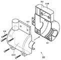
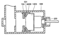
また、出願人が知り得る他の防振支持ゴムの形態について、図9から図13を参照して説明する。モータを収納するモータケース500は、2分割構造(第1ケース500A,第2ケース500B)からなり、各ケースに設けられた、ビス固定スロット502およびビス穴503を利用して、ビス504により、各ケースが一体となるように固定される。
Further, other vibration-proof support rubber forms that the applicant can know will be described with reference to FIGS. 9 to 13. The
第1ケース500Aおよび第2ケース500Bのモータ収納部分には、モータ外径のランクにより、またはモータメーカにより、通常2から3種類のモータを収納する必要がある。通常、それらのモータの差異は、一般的には、モータの軸方向の長さの差異である場合が大多数である。そこで、この種々のモータを同一のモータケース500に収納するために、図9に示すように、第1ケース500Aおよび第2ケース500Bの内周面に設けたリブ501を利用して、モータケース500内にモータを固定する方法が採用されている。
In the motor housing portions of the
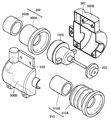
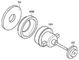
具体的には、軸方向の長さが短いモータ100Sにおいては、図10および図11に示すように、固定防振ゴム200を回転軸側に勘合し、ファン外径側に防振ゴム600Bを勘合させるとともに、モータ収納用板700をモータケース500の収納部に設けたリブ501の間に挟むことにより、防振ゴム600Bとモータ収納用板700との間にシール面を作ることで、モータ100Sから発生する振動を抑制するとともに負圧保持を確保可能な、モータ100Sの収納を実現している。
Specifically, in the
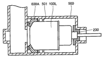
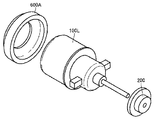
一方、軸方向の長さが長いモータ100Lにおいては、図12および図13に示すように、固定防振ゴム200を回転軸側に勘合し、ファン外径側に防振ゴム600Aを勘合させて、第1ケース500Aおよび第2ケース500Bのモータ収納部分にモータ100Lを固定し、固定防振ゴム200および防振ゴム600Aにより、モータ100Lから発生する振動を抑制するとともに負圧保持を確保している。
On the other hand, in the
このように、リブ501およびモータ収納用板700を適宜利用することにより、1種類のモータケース500において、種類の異なるモータの収納を可能としている。
しかし、図9〜図13に示したモータの収納構造には、以下に示す問題が挙げられる。 However, the motor storage structure shown in FIGS. 9 to 13 has the following problems.
(1)収納可能なモータは、モータケース内に設けるリブの位置により決まるため、モータ長さが異なる多種類のモータには対応できない。 (1) Since the motor which can be accommodated is determined by the position of the rib provided in the motor case, it cannot cope with many types of motors having different motor lengths.
(2)モータケース内へのモータ組み込み時に、リブ501にはめ込むためのモータ収納用板700が必要となり、モータ収納用板700の部品費(金型費用含む)、組立タイムの延長による、製造コストの上昇が問題となる。また、リブ501のはめ込み忘れや、はめ込み不良も問題となる。
(2) When the motor is incorporated into the motor case, the
したがって、この発明は上記課題を解決するためになされたものであり、1つのモータケースであっても、製造コストの上昇を招くことなく、モータ長さが異なる多種類のモータを収納可能とする、電気掃除機用モータ防振支持部材およびそのモータ防振支持部材を備えた電気掃除機を提供することにある。 Accordingly, the present invention has been made to solve the above-described problem, and even with one motor case, it is possible to store various types of motors having different motor lengths without increasing the manufacturing cost. Another object is to provide a motor vibration-proof support member for a vacuum cleaner and a vacuum cleaner provided with the motor vibration-proof support member.
上記目的を達成するため、この発明に基づいた電気掃除機用モータ防振支持部材においては、第1の空間と第2の空間とを有するモータケースと、上記第2の空間を上記第1の空間よりも負圧状態にするため、上記第1の空間と上記第2の空間とを区画するように配置される電気掃除機用モータとを備え、上記モータケース内に上記電気掃除機用モータを配置するために用いられる、電気掃除機用モータ防振支持部材であって、この電気掃除機用モータ防振支持部材は、以下の特徴を有している。 In order to achieve the above object, in a motor vibration isolating support member for a vacuum cleaner according to the present invention, a motor case having a first space and a second space, and the second space are defined as the first space. A vacuum cleaner motor arranged to partition the first space and the second space in order to make a negative pressure state than the space, and the vacuum cleaner motor in the motor case This is a motor anti-vibration support member for a vacuum cleaner, which is used for arranging the electric vacuum cleaner, and has the following characteristics.
本発明に基づく電気掃除機用モータ防振支持部材は上記電気掃除機用モータの負圧発生口を取囲むようにして、上記電気掃除機用モータに連結される円筒状受部領域と、弾性部材からなり、上記円筒状受部領域と上記第2の空間とを連結するため、上記円筒状受部領域に対し連続して設けられる円筒状スカート領域とを有する、第1防振支持部材と、上記円筒状スカート領域の内周面に沿って配設され、上記第1防振支持部材よりも硬い材質からなる円筒形状の第2防振支持部材とを備える。 The motor anti-vibration support member for a vacuum cleaner according to the present invention includes a cylindrical receiving region connected to the vacuum cleaner motor and an elastic member so as to surround the negative pressure generating port of the vacuum cleaner motor. A first anti-vibration support member having a cylindrical skirt region provided continuously with respect to the cylindrical receiving portion region for connecting the cylindrical receiving portion region and the second space; A cylindrical second anti-vibration support member disposed along the inner peripheral surface of the cylindrical skirt region and made of a material harder than the first anti-vibration support member.
本発明にける電気掃除機用モータ防振支持部材およびそのモータ防振支持部材を備えた電気掃除機によれば、少なくとも、第1防振支持部材の円筒状スカート領域が弾性部材から構成されることにより、モータの軸方向に沿った伸縮を可能とする。また、円筒状スカート領域の内周面には、この第1防振支持部材よりも硬い材質からなる円筒形状の第2防振支持部材が装着されるため、モータの負圧発生時においても、この円筒状スカート領域の形状を維持させておくことが可能となる。 According to the motor anti-vibration support member for a vacuum cleaner and the electric vacuum cleaner provided with the motor anti-vibration support member according to the present invention, at least the cylindrical skirt region of the first anti-vibration support member is composed of an elastic member. This enables expansion and contraction along the axial direction of the motor. Further, since the cylindrical second anti-vibration support member made of a material harder than the first anti-vibration support member is attached to the inner peripheral surface of the cylindrical skirt region, even when negative pressure is generated in the motor, It becomes possible to maintain the shape of this cylindrical skirt region.
これにより、モータ長さが異なる多種類のモータをモータケース内に収納する場合であっても、円筒状スカート領域の伸縮によりモータとモータケースとの間における隙間の発生を防止する。また、円筒状スカート領域の形状は、第2防振支持部材により維持される。その結果、モータの駆動による減圧状態に悪影響を及ぼすことなく、1つのモータケースであっても、モータ長さが異なる多種類のモータをモータケース内に収納することが可能になる。たとえば、円筒状スカート領域を蛇腹形状にすることで、円筒状スカート領域を軸方向に沿って大きく伸び縮みさせることが可能となり、収納可能なモータ種類の拡大を図ることが可能になる。 Accordingly, even when various types of motors having different motor lengths are accommodated in the motor case, the occurrence of a gap between the motor and the motor case is prevented by the expansion and contraction of the cylindrical skirt region. Further, the shape of the cylindrical skirt region is maintained by the second vibration-proof support member. As a result, various types of motors having different motor lengths can be accommodated in the motor case even in one motor case without adversely affecting the decompressed state due to the driving of the motor. For example, by making the cylindrical skirt region into a bellows shape, the cylindrical skirt region can be greatly expanded and contracted along the axial direction, and the types of motors that can be stored can be expanded.
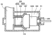
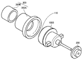
以下、この発明に基づいた実施の形態における電気掃除機用モータ防振支持部材について、図を参照しながら説明する。まず、図1および図2を参照して、本実施の形態における電気掃除機用モータ防振支持部材300の構造について説明する。なお、図1は、モータケース500にモータ100Sを収納した状態での部分断面図であり、図2は、モータ100Sおよび電気掃除機用モータ防振支持部材300の構造を示す全体斜視図である。なお、背景技術において説明したものと同一または相当部分については、同一の参照番号を付すことにより、重複する説明は繰り返さないこととする。
Hereinafter, a motor vibration isolating support member for a vacuum cleaner according to an embodiment based on the present invention will be described with reference to the drawings. First, with reference to FIG. 1 and FIG. 2, the structure of the motor
(電気掃除機用モータ防振支持部材300)
図1および図2を参照して、モータ100Sを収納すべきモータケース500は、第1の空間(大気圧空間)R1と第2の空間(負圧空間)R2とを有し、第2の空間R2を第1の空間R1よりも負圧状態にするため、第1の空間R1と第2の空間R2とを区画するように電気掃除機用モータ100Sが配置される。このモータケース500は、図9を用いて説明したように、2分割構造からなる。
(Motor
Referring to FIGS. 1 and 2, a
本実施の形態における電気掃除機用モータ防振支持部材300は、第1防振支持部材300Aと、第2防振支持部材300Bとを有している。第1防振支持部材300Aは、電気掃除機用モータ100Sの負圧発生口110側を取囲むように覆い、電気掃除機用モータ100Sのファン領域に連結される円筒状受部領域301と、この円筒状受部領域301と第2の空間R2とを連結するため、円筒状受部領域301に対し連続して設けられる円筒状スカート領域302とを有している。
The motor vibration-
本実施の形態における第1防振支持部材300Aは、全体がゴム(硬度50−60度)等の弾性部材からなる一体成型品である。なお、必ずしも、第1防振支持部材300Aは一体成型品である必要はなく、円筒状スカート領域302のみを上述の弾性部材から構成し、円筒状受部領域301は、電気掃除機用モータ100Sのファン領域に隙間無く連結される形状および構造であれば、特に、弾性部材に限定されるものではない。
The first
第2防振支持部材300Bは、円筒状スカート領域302の内周面に沿って配設され、第1防振支持部材300Aよりも硬い材質からなり、円筒形状を有している。具体的な材質としては、ABS樹脂等の硬質の樹脂材料が挙げられる。この第2防振支持部材300Bを、円筒状スカート領域302の内周面に沿って配設することで、モータ100Sの負圧発生時においても、モータ100Sの支持が不完全にならないよう骨材として作用し、円筒状スカート領域302の形状を維持させておくことが可能となる。
The second vibration
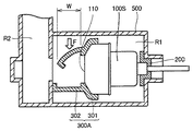
ここで、第2防振支持部材300Bを配設しない場合について、図3を参照して説明する。第2防振支持部材300Bを配設しない場合、たとえば幅(軸方向長さW)15mm、直径120mmの円筒状スカート領域302に真空圧24.5kPa(2500mmH2O)が掛かると、円筒状スカート領域302には約44.1N(4.5kgf)の力が加わる結果、変形、真空漏れ、モータ支持外れに陥ることになる(図3中矢印F)。一方、第2防振支持部材300Bを配設しておくことで、第2防振支持部材300Bはこの力を真空側から支え、円筒状スカート領域302の変形を防ぎ、また、この真空圧を利用して、モータ100Sを真空壁側に押し付ける役目も有する。
Here, the case where the 2nd
(電気掃除機用モータ防振支持部材の他の形態)
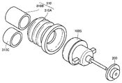
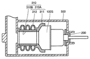
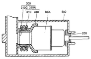
モータ長さが大きく異なる3種以上のモータを、同じモータケース500に収容する必要がある場合、以下に示す形態の電気掃除機用モータ防振支持部材310が考えられる。この電気掃除機用モータ防振支持部材310について、図4から図6を参照して説明する。なお、図4は、モータ長さが短いモータ100Sに、電気掃除機用モータ防振支持部材310を適用した場合の、分解斜視図であり、図5は、モータ100Sを収容した場合の断面図である。また、図6は、モータ長さがモータ100Sよりも長いモータ100Lを収容した場合の縦断面図である。
(Other forms of motor anti-vibration support member for vacuum cleaner)
When it is necessary to accommodate three or more types of motors having greatly different motor lengths in the
図4に示すように、この電気掃除機用モータ防振支持部材310においては、上述の第1防振支持部材300Aに相当する第1防振支持部材310Aの円筒状スカート領域312が蛇腹形状に設けられている。これにより、円筒状スカート領域312を軸方向に沿って大きく伸び縮みさせることを可能としている。その結果、モータ100Sに対応した長さの第2防振支持部材310B、モータ100Lに対応した長さの第2防振支持部材310Cを予め準備しておくことで、モータ100Sをモータケース500に収容する場合には、図5に示すように、第2防振支持部材310Bを用いることにより、第2防振支持部材310Bが軸方向に大きく引伸ばされた状態が保持さる。一方、モータ100Lをモータケース500に収容する場合には、図6に示すように、第2防振支持部材310Cを用いることにより、第2防振支持部材310Bが軸方向に大きく押し縮められた状態が保持される。
As shown in FIG. 4, in the motor vibration-
このように、第1防振支持部材310Aの円筒状スカート領域312を蛇腹形状にすることで、モータ長さに応じて、それぞれの防振ゴムを製作する必要がない。また、防振支持部材の長さをモータ長さに応じて調整するだけで、モータ長さが大きく異なる3種以上のモータを、同じモータケース500に収容することが可能となる。しかも、防振支持部材により真空圧にも耐え得る。
In this way, by forming the
以上、従来の電気掃除機用モータ防振支持部材によれば、先ずモータケースに予めモータ長さに応じた調整リブを作成する必要があり、採用モータが変更になると、金型修正が必要となるため、製造コストの上昇が問題となっていた。また、モータ収納用板を組み合わせ、その後、モータ+モータ防振支持部材+固定防振ゴムの組品をはめ込む組立は、複雑でこの部分のずれで真空度に不良が生じることがあった。 As described above, according to the conventional motor vibration-proof support member for a vacuum cleaner, it is necessary to first prepare an adjustment rib corresponding to the motor length in advance in the motor case, and when the adopted motor is changed, the mold needs to be corrected. Therefore, an increase in manufacturing cost has been a problem. In addition, the assembly in which the motor housing plate is combined and then the assembly of the motor, the motor vibration isolating support member, and the fixed vibration isolating rubber is complicated, and the degree of vacuum may be deteriorated due to the deviation of this portion.
しかし、上記本実施の形態における電気掃除機用モータ防振支持部材によれば、第1防振支持部材と第2防振支持部材とは予め、ゴム製作メーカにて、事前に組立ておくことができるため、真空度を気にすることなく、モータ+モータ防振支持部材+固定防振ゴムのセットを、モータケースにはめ込むことにより、組立を完成させることが可能となる。 However, according to the motor vibration-proof support member for a vacuum cleaner in the present embodiment, the first vibration-proof support member and the second vibration-proof support member can be assembled in advance by a rubber manufacturer. Therefore, without worrying about the degree of vacuum, the assembly can be completed by fitting a set of motor + motor vibration-proof support member + fixed vibration-proof rubber into the motor case.
また、円筒状スカート領域が蛇腹形状の第1防振支持部材を用いることで、第2防振支持部材の変更だけで多くのモータが同じメインボデイのモータケースに搭載することが可能となる。 Further, by using the first anti-vibration support member having the bellows-shaped cylindrical skirt region, many motors can be mounted on the same main body motor case only by changing the second anti-vibration support member.
(電気掃除機1000の構造)
上記構成を備える電気掃除機用モータ防振支持部材300,310を適用した電気掃除機の構造について、図7および図8を参照して簡単に説明する。なお、図7(a)は、正面側から見た電気掃除機1000の全体斜視図であり、図7(b)は、背面側から見た電気掃除機1000の全体斜視図である。また、図8は、電気掃除機用モータ防振支持部材300または電気掃除機用モータ防振支持部材310を用いた場合の、モータケース500の分解斜視図である。
(Structure of vacuum cleaner 1000)
A structure of the vacuum cleaner to which the motor vibration-
本電気掃除機1000は、アップライト型の電気掃除機である。構成としては、ノズルヘッド(床のゴミを吸い取る部分で、底に開口部分があり、アジテータブラシで床、絨毯からゴミを吸込む。)1001、サクションホース(ノズルヘッドで吸込んだゴミをサイクロン分離のために、サイクロンカップに導くホース)1002、サイクロンカップ(ゴミと空気を分離してカップに溜めモータ側にきれいな空気だけを流す)1003、メインボデイ(サイクロンカップ、後述のハンドル、その他部品の組立の基本骨組み部分)1004、および、ハンドル(ユーザーが掃除機を操作するとき握る部分)1005を備える。
This
上記電気掃除機用モータ防振支持部材300,310によりモータケース500に収容されるモータは、真空を生じて、掃除機1000のノズルヘッド1001の、床面からの粉塵の吸込み、サイクロンカップ1003におけるゴミ分離の気流源の役目を担保することとなる。
The motor housed in the
なお、今回開示した上記実施の形態はすべての点で例示であって、限定的な解釈の根拠となるものではない。したがって、本発明の技術的範囲は、上記した実施の形態のみによって解釈されるのではなく、特許請求の範囲の記載に基づいて画定される。また、特許請求の範囲と均等の意味および範囲内でのすべての変更が含まれる。 In addition, the said embodiment disclosed this time is an illustration in all the points, Comprising: It does not become the basis of limited interpretation. Therefore, the technical scope of the present invention is not interpreted only by the above-described embodiments, but is defined based on the description of the claims. Further, all modifications within the meaning and scope equivalent to the scope of the claims are included.
100L,100S モータ、110 負圧発生口、200 固定防振ゴム、300,310 電気掃除機用モータ防振支持部材、300A,310A 第1防振支持部材、300B,310B,310C 第2防振支持部材、301,311 円筒状受部領域、302,312 円筒状スカート領域、500 モータケース、500A 第1ケース、500B 第2ケース、502 ビス固定スロット、503 ビス穴、504 ビス、1000 電気掃除機、1001 ノズルヘッド、1002 サクションホース、1003 サイクロンカップ、1004 メインボデイ、1005 ハンドル、R1 第1の空間(大気圧空間)、R2 第2の空間(負圧空間)。 100L, 100S motor, 110 negative pressure generating port, 200 fixed anti-vibration rubber, 300, 310 motor anti-vibration support member for vacuum cleaner, 300A, 310A first anti-vibration support member, 300B, 310B, 310C second anti-vibration support Member, 301, 311 cylindrical receiving area, 302, 312 cylindrical skirt area, 500 motor case, 500A first case, 500B second case, 502 screw fixing slot, 503 screw hole, 504 screw, 1000 electric vacuum cleaner, 1001 Nozzle head, 1002 Suction hose, 1003 Cyclone cup, 1004 main body, 1005 handle, R1 first space (atmospheric pressure space), R2 second space (negative pressure space).
Claims (3)
当該電気掃除機用モータ防振支持部材は、
前記電気掃除機用モータの負圧発生口を取囲むようにして、前記電気掃除機用モータに連結される円筒状受部領域と、
弾性部材からなり、前記円筒状受部領域と前記第2の空間とを連結するため、前記円筒状受部領域に対し連続して設けられる円筒状スカート領域とを有する、第1防振支持部材と、
前記円筒状スカート領域の内周面に沿って配設され、前記第1防振支持部材よりも硬い材質からなる円筒形状の第2防振支持部材と、
を備える、電気掃除機用モータ防振支持部材。 A motor case having a first space and a second space, and the first space and the second space are partitioned in order to make the second space a negative pressure state than the first space. A vacuum cleaner motor disposed so as to be used in order to dispose the vacuum cleaner motor in the motor case.
The motor anti-vibration support member for the vacuum cleaner is
A cylindrical receiving region connected to the vacuum cleaner motor so as to surround the negative pressure generating port of the vacuum cleaner motor;
A first anti-vibration support member comprising an elastic member and having a cylindrical skirt region provided continuously with respect to the cylindrical receiving region to connect the cylindrical receiving region and the second space When,
A cylindrical second anti-vibration support member disposed along an inner peripheral surface of the cylindrical skirt region and made of a material harder than the first anti-vibration support member;
A motor vibration-proof support member for a vacuum cleaner, comprising:
Priority Applications (1)
| Application Number | Priority Date | Filing Date | Title |
|---|---|---|---|
| JP2004048215A JP2005237461A (en) | 2004-02-24 | 2004-02-24 | Motor anti-vibration support member for electric vacuum cleaner and electric vacuum cleaner provided with the motor anti-vibration support member |
Applications Claiming Priority (1)
| Application Number | Priority Date | Filing Date | Title |
|---|---|---|---|
| JP2004048215A JP2005237461A (en) | 2004-02-24 | 2004-02-24 | Motor anti-vibration support member for electric vacuum cleaner and electric vacuum cleaner provided with the motor anti-vibration support member |
Publications (1)
| Publication Number | Publication Date |
|---|---|
| JP2005237461A true JP2005237461A (en) | 2005-09-08 |
Family
ID=35019831
Family Applications (1)
| Application Number | Title | Priority Date | Filing Date |
|---|---|---|---|
| JP2004048215A Withdrawn JP2005237461A (en) | 2004-02-24 | 2004-02-24 | Motor anti-vibration support member for electric vacuum cleaner and electric vacuum cleaner provided with the motor anti-vibration support member |
Country Status (1)
| Country | Link |
|---|---|
| JP (1) | JP2005237461A (en) |
Cited By (2)
| Publication number | Priority date | Publication date | Assignee | Title |
|---|---|---|---|---|
| JP2010051135A (en) * | 2008-08-25 | 2010-03-04 | Hitachi Ltd | Rotary electric machine |
| KR20110139262A (en) * | 2009-03-17 | 2011-12-28 | 코닌클리케 필립스 일렉트로닉스 엔.브이. | Vacuum cleaner |
-
2004
- 2004-02-24 JP JP2004048215A patent/JP2005237461A/en not_active Withdrawn
Cited By (4)
| Publication number | Priority date | Publication date | Assignee | Title |
|---|---|---|---|---|
| JP2010051135A (en) * | 2008-08-25 | 2010-03-04 | Hitachi Ltd | Rotary electric machine |
| KR20110139262A (en) * | 2009-03-17 | 2011-12-28 | 코닌클리케 필립스 일렉트로닉스 엔.브이. | Vacuum cleaner |
| JP2012520719A (en) * | 2009-03-17 | 2012-09-10 | コーニンクレッカ フィリップス エレクトロニクス エヌ ヴィ | Vacuum cleaner |
| KR101690316B1 (en) | 2009-03-17 | 2016-12-27 | 코닌클리케 필립스 엔.브이. | Vacuum cleaner |
Similar Documents
| Publication | Publication Date | Title |
|---|---|---|
| CN101945606B (en) | Electric vacuum cleaner | |
| CN118175950A (en) | Cleaner head and cleaner including the same | |
| CN101357050B (en) | Dust collector with filter bag inside and filter bag used by the dust collector | |
| JP2009183610A (en) | Electric vacuum cleaner | |
| EP3280307A1 (en) | A device for mounting a motor assembly of an electric appliance | |
| KR101252346B1 (en) | Electric cleaner and method of producing the same | |
| KR100504468B1 (en) | Motor Case for Vacuum Cleaner | |
| JP5561862B2 (en) | Vacuum cleaner with attached brush | |
| JP7040299B2 (en) | Vacuum cleaner | |
| CN223124707U (en) | Buffer for motor, motor assembly and cleaning device including the same | |
| JP2019001291A (en) | Air intake duct | |
| JP2501682Y2 (en) | Spoker case open pipe port mounting structure | |
| JP3956231B2 (en) | Electric vacuum cleaner | |
| CN112576531A (en) | Fan structure, fan wind channel subassembly and robot of sweeping floor | |
| JP5197044B2 (en) | Electric vacuum cleaner | |
| JP6915957B2 (en) | A suction tool with a rotating brush and a vacuum cleaner with it | |
| JP2011224150A (en) | Electric cleaner | |
| CN110403518A (en) | Cleaning equipment | |
| JP2005341733A (en) | Motor support structure and electric device provided with the same | |
| JPH07136093A (en) | Vacuum cleaner | |
| CN121606188A (en) | Lightweight hand-held dust collector | |
| JPS6053618B2 (en) | Vacuum cleaner fan motor support device | |
| JP2010057748A (en) | Vacuum cleaner | |
| JPS644781B2 (en) | ||
| JP2004283407A (en) | Vacuum cleaner suction tool |
Legal Events
| Date | Code | Title | Description |
|---|---|---|---|
| A300 | Withdrawal of application because of no request for examination |
Free format text: JAPANESE INTERMEDIATE CODE: A300 Effective date: 20070501 |