JP2005242534A - Information providing system and data generation apparatus - Google Patents
Information providing system and data generation apparatus Download PDFInfo
- Publication number
- JP2005242534A JP2005242534A JP2004049468A JP2004049468A JP2005242534A JP 2005242534 A JP2005242534 A JP 2005242534A JP 2004049468 A JP2004049468 A JP 2004049468A JP 2004049468 A JP2004049468 A JP 2004049468A JP 2005242534 A JP2005242534 A JP 2005242534A
- Authority
- JP
- Japan
- Prior art keywords
- data
- information
- output
- unit
- format
- Prior art date
- Legal status (The legal status is an assumption and is not a legal conclusion. Google has not performed a legal analysis and makes no representation as to the accuracy of the status listed.)
- Pending
Links
Images


Landscapes
- Arrangements For Transmission Of Measured Signals (AREA)
Abstract
【課題】 建物や施設等に設置されたセンサーから出力されたデータの利便性を向上させることができると共に、ユーザに対して有益な情報を提示することができる情報提供システムおよびデータ生成装置を提供する。
【解決手段】 オブジェクト化部106は、記憶部110から設定情報を読み出して参照すると共に、内部クロックが示す時間情報(時刻情報)を参照する。設定情報は、場所、データの種別、およびデータの形式等に関する情報を含む。オブジェクト化部106は、この設定情報および時間情報に基づいて、センサーからの出力結果を示すデジタルデータからオブジェクトデータを生成する。このオブジェクトデータは、汎用的な意味付けがなされていると共に、識別可能なデータとなる。
【選択図】 図2
PROBLEM TO BE SOLVED: To provide an information providing system and a data generation device capable of improving the convenience of data output from a sensor installed in a building or a facility and presenting useful information to a user To do.
An object forming unit reads out and refers to setting information from a storage unit and refers to time information (time information) indicated by an internal clock. The setting information includes information regarding the location, data type, data format, and the like. The object converting unit 106 generates object data from digital data indicating the output result from the sensor based on the setting information and time information. This object data has general meaning and is identifiable data.
[Selection] Figure 2
Description
本発明は、電力・環境・エネルギー等の分野におけるデータおよび情報の活用を図った情報提供システムおよびデータ生成装置に関する。 The present invention relates to an information providing system and a data generation apparatus that make use of data and information in fields such as electric power, environment, and energy.
従来、建物等に設置された管理対象機器から情報を収集し、その情報に基づいたサービスを提供するシステムがある。例えば、特許文献1には、管理対象機器から収集した、管理対象機器の運転状態を示す情報に基づいて、管理対象機器の運転を制御するサーバーシステムが記載されている。また、特許文献2には、エネルギー低減を目的とするプログラムによって管理対象機器を運用すると共に、管理対象機器から運転状況の計測値を収集し、運用結果を今後の運用にフィードバックさせる設備管理装置が記載されている。また、特許文献3には、分散配置された圧縮機から情報を取り込み、圧縮機の運転状況を示す情報を保守・メンテナンス部門に送信することにより、圧縮機の故障を防止することができる遠隔監視システムが記載されている。
従来、建物や施設等に設置されたセンサーから出力されたデータは単なる数値を示すだけのものであり、そのデータの解釈はそのデータを利用するシステムに依存していた。したがって、あるシステムにおいては意味のあるデータであっても、データを解釈するための仕様が異なる他のシステムにおいては、意味を持たない(あるいは解釈の結果が元のデータの意味と異なる)データとなってしまうという問題があった。 Conventionally, data output from sensors installed in buildings, facilities, and the like merely indicate numerical values, and interpretation of the data depends on a system that uses the data. Therefore, even if the data is meaningful in a certain system, it has no meaning (or the interpretation result is different from the original data) in other systems with different specifications for interpreting the data. There was a problem of becoming.
また、センサーから出力されたデータは単なる数値データであり、データ自身にはそのデータを識別するための情報が付加されていないため、多数のセンサーから出力されたデータを利用する場合に、膨大なデータの中からあるデータを識別することが困難であった。さらに、センサーから出力されたデータに基づいて、管理対象機器の計測・制御を行う計測・制御機器から出力されるデータの形式は、その計測・制御機器を管理する専門メーカに依存した形式であった。そのため、データ間相互の互換性や再利用性が大変低く、そのデータを利用するシステムやサービスとの連携・連動が困難であった。以上のことから、センサーから出力されたデータに基づいて、ユーザに対して有益な情報を提示することが困難であった。 In addition, the data output from the sensor is simply numeric data, and no information for identifying the data is added to the data itself. Therefore, when data output from a large number of sensors is used, an enormous amount of data is output. It was difficult to identify certain data from the data. Furthermore, the format of the data output from the measurement / control device that performs measurement / control of the managed device based on the data output from the sensor is a format that depends on the specialized manufacturer that manages the measurement / control device. It was. Therefore, the compatibility and reusability between data is very low, and it is difficult to link and link with systems and services that use the data. From the above, it has been difficult to present useful information to the user based on the data output from the sensor.
本発明は、上述した問題点に鑑みてなされたものであって、建物や施設等に設置されたセンサーから出力されたデータの利便性を向上させることができると共に、ユーザに対して有益な情報を提示することができる情報提供システムおよびデータ生成装置を提供することを目的とする。 The present invention has been made in view of the above-described problems, and can improve the convenience of data output from sensors installed in buildings, facilities, and the like, and is useful information for the user. It is an object to provide an information providing system and a data generation apparatus capable of presenting information.
本発明は上記の課題を解決するためになされたもので、請求項1に記載の発明は、センサーからの出力値を示す出力データに対して、該出力データを識別するための情報を付加し、オブジェクトデータを生成するデータ生成装置と、ネットワークを介して前記データ生成装置から前記オブジェクトデータを取得し、該オブジェクトデータに基づいた情報を、ユーザが所持するユーザ端末へ、前記ネットワークを介して送信するネットワーク装置とを具備することを特徴とする情報提供システムである。
The present invention has been made to solve the above problems, and the invention according to
請求項2に記載の発明は、請求項1に記載の情報提供システムにおいて、前記データ生成装置は、前記オブジェクトデータの生成に必要な設定情報を記憶する記憶手段と、前記記憶手段から前記設定情報を読み出すと共に、該設定情報および時間情報に基づいて、前記出力データに対して、該出力データを識別するための情報を付加する情報付加手段とを具備することを特徴とする。 According to a second aspect of the present invention, in the information providing system according to the first aspect, the data generation device stores setting information necessary for generating the object data, and the setting information from the storage unit. And an information adding means for adding information for identifying the output data to the output data based on the setting information and the time information.
請求項3に記載の発明は、請求項1または請求項2に記載の情報提供システムにおいて、前記オブジェクトデータは、前記出力データと、時間情報に基づいた時間を示すデータと、場所を示すデータと、前記出力データの種別および形式を示すデータとを含むことを特徴とする。 According to a third aspect of the present invention, in the information providing system according to the first or second aspect, the object data includes the output data, data indicating time based on time information, and data indicating a place. And data indicating the type and format of the output data.
請求項4に記載の発明は、請求項2または請求項3に記載の情報提供システムにおいて、前記設定情報は、場所を識別する情報と、前記出力データの種別および形式を識別する情報とを含むことを特徴とする。 According to a fourth aspect of the present invention, in the information providing system according to the second or third aspect, the setting information includes information for identifying a location and information for identifying the type and format of the output data. It is characterized by that.
請求項5に記載の発明は、請求項4に記載の情報提供システムにおいて、前記設定情報はさらに、前記出力データのデータ形式を変換するための変換情報を含むことを特徴とする。 According to a fifth aspect of the present invention, in the information providing system according to the fourth aspect, the setting information further includes conversion information for converting a data format of the output data.
請求項6に記載の発明は、センサーからの出力値を示す出力データに対して、該出力データを識別するための情報を付加し、オブジェクトデータを生成するデータ生成装置である。 According to a sixth aspect of the present invention, there is provided a data generation device that generates object data by adding information for identifying output data to output data indicating an output value from a sensor.
請求項7に記載の発明は、請求項6に記載のデータ生成装置において、前記オブジェクトデータの生成に必要な設定情報を記憶する記憶手段と、前記記憶手段から前記設定情報を読み出すと共に、該設定情報および時間情報に基づいて、前記出力データに対して、該出力データを識別するための情報を付加する情報付加手段とを具備することを特徴とする。 According to a seventh aspect of the present invention, in the data generation device according to the sixth aspect of the present invention, the setting information necessary for generating the object data is stored, the setting information is read from the storage unit, and the setting information is read out. And an information adding unit for adding information for identifying the output data to the output data based on the information and the time information.
請求項8に記載の発明は、請求項6または請求項7に記載のデータ生成装置において、前記オブジェクトデータは、前記出力データと、時間情報に基づいた時間を示すデータと、場所を示すデータと、前記出力データの種別および形式を示すデータとを含むことを特徴とする。 According to an eighth aspect of the present invention, in the data generation device according to the sixth or seventh aspect, the object data includes the output data, data indicating time based on time information, and data indicating a place. And data indicating the type and format of the output data.
請求項9に記載の発明は、請求項7または請求項8に記載のデータ生成装置において、前記設定情報は、場所を識別する情報と、前記出力データの種別および形式を識別する情報とを含むことを特徴とする。 According to a ninth aspect of the present invention, in the data generation device according to the seventh or eighth aspect, the setting information includes information for identifying a location and information for identifying a type and format of the output data. It is characterized by that.
請求項10に記載の発明は、請求項9に記載のデータ生成装置において、前記設定情報はさらに、前記出力データのデータ形式を変換するための変換情報を含むことを特徴とする。 According to a tenth aspect of the present invention, in the data generation device according to the ninth aspect, the setting information further includes conversion information for converting a data format of the output data.
本発明によれば、建物や施設等に設置されたセンサーから出力されたデータに対して、データを唯一に特定するための意味付けを行うようにしたので、センサーから出力されたデータの利便性を向上させることができるという効果が得られる。また、ユーザに対して有益な情報を提示することができるという効果も得られる。 According to the present invention, meaning is given to uniquely specify data for data output from sensors installed in buildings, facilities, etc., so the convenience of data output from sensors The effect that can be improved is obtained. Moreover, the effect that useful information can be shown with respect to a user is also acquired.
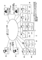
以下、図面を参照し、本発明を実施するための最良の形態について説明する。図1は、本発明の一実施形態による情報提供システムの構成を示すブロック図である。情報提供システムは、ネットワーク1、データ生成装置10、ユーザー端末20、サーバーシステム30〜32、および分析サーバー40を備えている。ネットワーク1は、公衆インターネット回線や、電話網、光ネットワーク等の様々な形態のネットワークである。
The best mode for carrying out the present invention will be described below with reference to the drawings. FIG. 1 is a block diagram showing a configuration of an information providing system according to an embodiment of the present invention. The information providing system includes a
データ生成装置10は、建物・施設・設備等に設置されたセンサーから出力されたデータに対して汎用的な意味付けを行い、オブジェクトデータを生成する。ユーザー端末20は、情報提供の対象となるユーザー(クライアント)によって操作される端末である。ユーザ端末20は、汎用のパーソナルコンピュータ、携帯電話、PDA(Personal Digital Asistance)等の、ネットワーク接続機能を備えた端末である。ユーザー端末20の数は任意である。
The
サーバーシステム30〜32は、データ生成装置10から出力されたデータを、ネットワーク1を介して取得し、取得したデータに対して様々な処理を行う。サーバーシステム30〜32の構成は以下のとおりである。サーバーシステム30は、WEBサーバー、アプリケーションサーバー、およびデータベースサーバーを備えている。サーバーシステム31は、ネットワーク1に接続されたWEBサーバー310、ネットワーク1に接続されたアプリケーションサーバー311、およびアプリケーションサーバー311に接続されたデータベースサーバー312を備えている。サーバーシステム32は、WEBサーバーおよびアプリケーションサーバーを備えたサーバーシステム320と、ネットワーク1に接続されたデータベースサーバー321とを備えている。分析サーバー40は、入力されたデータに対して様々な分析処理を行う。
The
上記のサーバーシステム30〜32内には、任意の数のサーバーが設置可能である。また、サーバーシステム30〜32は、図示した構成以外の構成であってもよい。すなわち、これらのサーバーシステム30〜32の構成に関しては、任意の拡張が可能である。サーバーシステム30〜32等には、ネットワーク1に対して接続する環境と、データ生成装置10およびユーザー端末20とデータの送受信を行う通信環境とを備えたネットワーク装置(WEBサーバー等のコンピュータ)が少なくとも備わっていればよい。
Any number of servers can be installed in the
各サーバーシステム30〜32および分析サーバー40とデータ生成装置10との通信は、SOAP(Simple Object Access Protocol)に基づいて行われる。SOAPはXML(Extensible Markup Language)形式で記述されたメッセージを用いて、HTTP(Hyper Text Transfer Protocol)等の通信プロトコルにより、ネットワーク上のオブジェクトデータにアクセスするためのプロトコルである。SOAPを用いた通信においては、HTTPやSMTP(Simple Mail Transfer Protocol)、FTP(File Transfer Protocol)等のプロトコルが下位プロトコルとして使用される。SOAPを用いた通信により、OS等の環境が異なるコンピュータ間におけるオブジェクトデータの通信が可能となる。なお、必ずしもSOAPを利用しなくても、他の汎用プロトコルによりオブジェクトデータを利用することができる。
Communication between each of the
データ生成装置10はセンサーから出力されたデータに基づいて、オブジェクトデータを生成し、サーバーシステム30等へ送信する。例えば、データ生成装置10がサーバーシステム30に対してデータを送信する場合、データ生成装置10は、まず受信可能かどうか問い合わせるための問い合わせ情報を含むメッセージデータをHTTP等のプロトコルに基づいて、サーバーシステム30に送信する。サーバーシステム30は受信したメッセージデータを解釈し、データ生成装置10へ返答するための返答情報を含むメッセージデータを作成する。続いて、サーバーシステム30はデータ生成装置10へメッセージデータを、HTTP等のプロトコルに基づいて送信する。データ生成装置10はこのメッセージデータを受信して解釈し、サーバーシステム10が受信可能状態であると判断した場合に、HTTP等のプロトコルに基づいて、オブジェクトデータに基づいたメッセージデータをサーバーシステム30へ送信する。
The
図2はデータ生成装置10の構成を機能的に示すブロック図である。データ生成装置10には、センサーS1〜Sm(mは正の整数)およびモニター/コントローラー50が接続されている。モニター/コントローラー50は、センサーs1〜sn(nは正の整数)を取り扱う専門メーカーによって設置された計測・制御機器やBAS(Building Automation System)等のモニターまたはコントローラーである。センサーS1〜Smおよびセンサーs1〜snは建物・設備等に設置された各種のセンサーである。これらのセンサーから出力されるデータは、電圧、電流、電力量、積算電力量、外気温度、および外気湿度等の施設や、設備、機器等の計測データと、異常状態を知らせるアラームデータとである。
FIG. 2 is a block diagram functionally showing the configuration of the
データ生成装置10は、入力部101、A/D変換部102、通信回路103、接続部104、パルス変換部105、オブジェクト化部106、入力部107、通信回路108、接続部109、記憶部110、汎用通信化部111、通信部112、通信回路113、インタフェース部114、無線インタフェース部115を備えている。
The
センサーS1〜Smおよびセンサーs1〜snから出力されるデータの形式は、アナログ、デジタル、またはパルスのいずれかである。センサーによっては、内部にA/D変換器を備え、デジタルデータを出力するものもある。また、電力積算量などの積算型のデータはパルス状のデータであることが多い。センサーS1〜Smから出力されたアナログ、デジタル、またはパルスのデータは、入力部101に入力される。
The format of data output from the sensors S1 to Sm and the sensors s1 to sn is either analog, digital, or pulse. Some sensors have an A / D converter inside and output digital data. In addition, the integration type data such as the integrated power amount is often pulsed data. Analog, digital, or pulse data output from the sensors S <b> 1 to Sm is input to the
A/D変換部102は、入力部101から出力されたアナログおよびパルスのデータをデジタル(デジタルパルス)データに変換し、通信回路103へ出力する。A/D変換部102は、デジタルデータに対してはデータの変換を行わない。デジタルデータは接続部104に入力される。パルス変換部105は、デジタルパルスデータに対して、単位時間当たりのパルス数を計上し、センサーによる計測値を示すデジタルデータへ変換する。オブジェクト化部106は、パルス変換部105および接続部109から出力されたデータに基づいて、意味付けのなされたオブジェクトデータを生成する。オブジェクト化部106による処理の詳細は後述する。
The A /
センサーs1〜snから出力されたデータはモニター/コントローラー50に入力される。モニター/コントローラー50からは、専門メーカに依存した形式のデジタルデータが出力される。このデジタルデータは、入力部107に入力され、通信回路108を介して、接続部109に入力される。このデジタルデータは、接続部109からオブジェクト化部106へ出力される。
Data output from the sensors s1 to sn is input to the monitor /
オブジェクト化部106はオブジェクトデータを生成し、記憶部110に格納する。記憶部110はオブジェクトデータを記憶すると共に、各種センサーからの出力データに関する情報やセンサーの設置場所等に関する情報を含む設定情報等を記憶する。汎用通信化部111は、オブジェクトデータを記憶部110から読み出し、そのオブジェクトデータに基づいて、XML形式のデータ(XML文書)を作成する。そして、汎用通信化部111は、作成したXML文書に対して、通信に必要な付帯情報を付加し、SOAPに基づいた形式のメッセージデータを生成する。また、汎用通信化部111は、外部のネットワークから入力されたメッセージデータを通信部112から受け取り、メッセージデータの解釈を行う機能も備えている。
The
通信部112は外部との通信に関する制御を行う。通信部112は、外部のネットワークから入力されたメッセージデータを通信回路113から取得し、汎用通信化部111へ出力する。また、通信部112は、汎用通信化部111から出力されたメッセージデータを通信回路113へ出力する。インタフェース部114は、通信ケーブルを介して外部のネットワーク(インターネット、LAN等)に接続される。無線インタフェース部115は、無線通信によって外部のネットワーク(インターネット、無線LAN等)に接続される。無線インタフェース部115は、例えば、カードスロットを備えている。そのカードスロットに無線LANカードが挿入されることにより、外部との無線通信が可能となる。
The
オブジェクト化部106、汎用通信化部111、および通信部112が有する機能は、例えば、コンピュータのCPU(中央処理装置)によって実現される。また、記憶部110は、例えば、ハードディスクドライブやメモリ内の記憶領域である。
The functions of the
データ生成装置10は、他のデータ生成装置10に対して、インタフェース部114または無線インタフェース部115を介して接続することができる。各種センサー同士が離れて点在している場合や、入力部101または入力部107の入力数に制限がある場合などには、データ生成装置10を複数接続して用いることができるので、システムの管理者は拡張性の高いシステムを構築することができる。
The
なお、データ生成装置10の構成は上記の構成に限定されない。例えば、図2の範囲A内の構成が同一の装置内に収められ、範囲B内の入力部101、A/D変換部102等はその装置とは独立して設置されていてもよいし、範囲Aおよび範囲B内の構成が全て同一の装置内に収められていてもよい。また、データ生成装置10内に、各種のセンサーが設けられていてもよい。
The configuration of the
さらに、入力部101および107は別個の構成であってもよいし、同一の構成であってもよい。すなわち、センサーS1〜Smからのデータが入力される入力ルートaと、センサーs1〜snからのデータが入力される入力ルートbは別個のルートであってもよいし、それらが統合された1つのルートであってもよい。
Furthermore, the
次に、記憶部110に格納されている設定情報を説明する。設定情報は、センサーが設置される場所に関する場所情報、センサーからの複数の出力データを識別するための識別情報、出力データの種別を示す種別情報、および出力データの形式に関する形式情報を含んでいる。
Next, setting information stored in the
場所情報は、センサーが設置される特定の建物や設備等の固有名称に関する情報である。識別情報は、オブジェクト化部106に入力されるデータを識別するための情報である。例えば、複数の信号線を用意し、各センサーからの出力データに対して個別に信号線を割り当てることにより、各出力データと各信号線とを1対1の関係で対応させることができる。また、複数のデジタルデータを多重化し、多重化したデータに対して1本の信号線を割り当てることも考えられる。この場合、複数の異なるデジタルデータに対して送信の順番が割り当てられ、概ねその順番に従ってデジタルデータが送信されるので、各デジタルデータが送信される順番と各デジタルデータとを1対1の関係で対応させることができる。識別情報は、以上のような対応関係を示す情報であり、物理的な結線の関係や通信規約等に基づいて、予め作成された情報である。
The location information is information related to a specific name of a specific building or facility where the sensor is installed. The identification information is information for identifying data input to the
種別情報は、データの種別に関する情報である。種別情報は、電圧値や、電流値、電力量、温度等を示す情報を含み、さらに詳細に言えば、瞬時電圧値や、瞬時電流値、積算電力量、外気温度、冷水供給温度等を示す情報を含む。また、種別情報は、これらのデータが最大値、最小値、平均値等のいずれであるのかを示す情報も含む。さらに、種別情報は、センサー等の異常に関係するデータを示す情報も含む。例えば、センサーは、故障やデータの未取得等の異常状態を検出した場合に、異常を示すアラームデータを出力することがある。種別情報は、以上のようなデータの種別に関する情報である。 The type information is information related to the type of data. The type information includes information indicating a voltage value, a current value, an electric energy, a temperature, and the like, and more specifically, an instantaneous voltage value, an instantaneous current value, an integrated electric energy, an outside air temperature, a cold water supply temperature, and the like. Contains information. The type information also includes information indicating whether the data is a maximum value, a minimum value, an average value, or the like. Further, the type information includes information indicating data related to abnormality such as a sensor. For example, the sensor may output alarm data indicating an abnormality when detecting an abnormal state such as failure or no data acquisition. The type information is information regarding the type of data as described above.
形式情報は、出力データの形式を示す情報である。形式情報は、データの単位に関する単位情報と、データのプレフィックスに関するプレフィックス情報とを含む。単位情報とは、データ種別とそのデータの単位とを対応付けた情報である。例えば、単位情報は、積算電力量を示す数値に対してWという単位を対応付け、外気温度を示す数値に対して℃という単位を対応付けるということを示している。プレフィックス情報は、データのプレフィックス(キロ、メガ等)に関する情報である。例えば、10というデータに対してWという単位が関係付けられていた場合に、その数値が10Wなのか、10kWなのかを特定するための情報がプレフィックス情報である。なお、上記の情報に対して付与された名称は、説明の便宜のために付与されたものであり、それによって実際のデータの形式が限定される訳ではない。 The format information is information indicating the format of the output data. The format information includes unit information related to the data unit and prefix information related to the data prefix. The unit information is information in which the data type is associated with the data unit. For example, the unit information indicates that a unit of W is associated with a numerical value indicating the integrated electric energy, and a unit of ° C. is associated with a numerical value indicating the outside air temperature. The prefix information is information regarding data prefixes (kilo, mega, etc.). For example, when a unit of W is associated with data of 10, information for specifying whether the numerical value is 10 W or 10 kW is prefix information. The names given to the above information are given for convenience of explanation, and the actual data format is not limited thereby.
次に、モニター/コントローラー50から出力されるデータについて説明する。モニター/コントローラー50から出力されるデータは専門メーカに依存した形式のデータである。専門メーカの中には、その形式に関する規約を公表しているものがあり、その規約に従えば、専門メーカに依存した形式のデータを汎用的な数値データに変換することが可能となる。記憶部110は、上記の変換に必要な変換情報を記憶している。オブジェクト化部106は、記憶部110から変換情報を読み出して参照し、接続部109から出力されたデータを汎用的な数値データに変換する。なお、専門メーカがデータの形式に関する規約を公表していない場合は、入力ルートaのように、センサーとデータ生成装置10とを直接接続してデータを取得すればよい。
Next, data output from the monitor /
次に、オブジェクト化部106によるオブジェクトデータの生成方法を説明する。オブジェクト化部106は、記憶部110から設定情報を読み出して参照すると共に、内部クロックが示す時間情報(時刻情報)を参照する。なお、オブジェクト化部106は、上記の設定情報をサーバーシステム30等のサーバーから読み出して参照してもよい。オブジェクト化部106は、設定情報および時間情報に基づいて、センサーからの出力結果を示すデジタルデータからオブジェクトデータを生成する。オブジェクトデータ中に含まれるオブジェクトの生成手法は以下のとおりである。オブジェクト化部106は、設定情報中の場所情報に基づいて、場所オブジェクトを生成する。場所オブジェクトは、センサーまたはデータ生成装置10が設置されている建物や設備等の固有名称に関係付けられている。また、オブジェクト化部106は、時間情報に基づいて、時間オブジェクトを生成する。時間オブジェクトは、オブジェクトデータが生成された時間(時刻)に関係付けられている。
Next, a method for generating object data by the
また、オブジェクト化部106は、設定情報中の種別情報に基づいて、計測ポイント名称オブジェクトを生成する。計測ポイント名称オブジェクトは、データの種別に関係付けられている。また、オブジェクト化部106は、設定情報中の形式情報に基づいて、測定データ単位オブジェクトと測定データ量の単位オブジェクトとを生成する。測定データ単位オブジェクトは、データの単位(W、V、A、℃等)に関係付けられている。測定データ量の単位オブジェクトは、データのプレフィックスに関係付けられている。
Further, the
また、オブジェクト化部106は、設定情報中の種別情報に基づいて、アラームデータのオブジェクトを生成する。アラームデータのオブジェクトは、故障やデータの未取得等の異常状態を示す不具合データに関係付けられている。アラームデータのオブジェクトは、不具合データがオブジェクト化部106に入力された場合に生成される。オブジェクト化部106は、以上の動作により、測定データに対して意味付けのなされたオブジェクトデータを生成する。
Further, the
図3は、オブジェクト化部106によって生成されたオブジェクトデータ1000の内容を示す参考図である。オブジェクトデータ1000は、場所オブジェクト1001、時間オブジェクト1002、計測ポイント名称オブジェクト1003、測定データ量1004、測定データ単位オブジェクト1005、測定データ量の単位オブジェクト1006、およびアラームデータのオブジェクト1007によって構成されている。測定データ量1004は、オブジェクト化部1006に入力された数値データである。
FIG. 3 is a reference diagram showing the contents of the
場所オブジェクト1001〜アラームデータのオブジェクト1007が測定データ量1004に関係付けられることにより、オブジェクトデータ1000は他のオブジェクトデータとの識別が可能なデータとなる。これにより、オブジェクトデータ1000は、情報提供システムのどこに存在していてもよい。
The
次に、情報提供システムにおいて、ユーザに対する情報提供の方法を説明する。データ生成装置10は、例えばサーバーシステム30に対して、データの受信が可能であるかどうか確認するための問い合わせ情報を含むメッセージデータを送信する。この場合、汎用通信化部111がメッセージデータを作成する。サーバーシステム30におけるサーバー(例えばWEBサーバー)はこのメッセージデータを受信し、データ生成装置10に対して返答するための返答情報を含むメッセージデータを作成してデータ生成装置10へ送信する。
Next, a method for providing information to the user in the information providing system will be described. The
このメッセージデータは、ネットワーク1を介して、インタフェース部114または無線インタフェース部115に入力される。メッセージデータは、通信回路113を介して、通信部112に入力される。通信部112は、このメッセージデータを汎用通信化部111へ出力する。汎用通信化部111は、メッセージデータを解釈し、サーバーが受信可能状態であるかどうかを判断する。
This message data is input to the
サーバーが受信可能状態である場合、汎用通信化部111はオブジェクトデータを記憶部110から読み出し、そのオブジェクトデータに基づいてXML文書を作成する。そして、汎用通信化部111は、作成したXML文書に対して、通信に必要な付帯情報を付加し、SOAPに基づいた形式のメッセージデータを生成する。続いて、汎用通信化部111は通信部112へメッセージデータを出力する。通信部112は、インタフェース部114または無線インタフェース部115へメッセージデータを出力する。このメッセージデータは、サーバーシステム30へ送信される。
When the server is in a receivable state, the general-
サーバーシステム30においては、WEBサーバーがデータ生成装置10からメッセージデータを受信し、メッセージデータの解釈を行う。WEBサーバーはメッセージデータの解釈によって、オブジェクトデータを取得する。WEBサーバーはアプリケーションサーバーからの要求に応じて、オブジェクトデータをアプリケーションサーバーへ渡す。アプリケーションサーバーは、オブジェクトデータをデータベースサーバーへ蓄積したり、データベースサーバーからオブジェクトデータを読み出して、データの加工を行ったりする。
In the
アプリケーションサーバーは、例えば、使用電力量を示すオブジェクトデータを読み出し、そのオブジェクトデータによって示される計測データに基づいて、特定の建物における毎分や毎時等の使用電力量を示すグラフ等を作成する。あるいは、アプリケーションサーバーは、特定の建物に設置された空調機器の温度を示すオブジェクトデータを読み出し、毎分や毎時等の温度を示すグラフ等を作成する。作成されたグラフに関する情報は、データベースサーバーに格納されたり、WEBサーバーからの要求に応じて、WEBサーバーへ渡されたりする。もちろん、アプリケーションサーバは電力や温度以外にも様々な計測データに関する情報を作成することができる。 For example, the application server reads object data indicating the amount of power used, and creates a graph or the like indicating the amount of power used per minute or hour in a specific building based on the measurement data indicated by the object data. Or an application server reads the object data which show the temperature of the air-conditioning equipment installed in the specific building, and produces the graph etc. which show temperature, such as every minute and every hour. Information about the created graph is stored in the database server, or passed to the WEB server in response to a request from the WEB server. Of course, the application server can create information related to various measurement data in addition to power and temperature.
ユーザー端末20から特定のデータの要求があった場合、サーバーシステム30におけるWEBサーバーは、要求されたデータに基づいてXML文書を作成し、SOAPに基づいた通信によってユーザー端末20へ送信する。ユーザー端末20のWEBブラウザ上では、要求したデータがグラフ等の形式で表示される。例えば、過去1週間の毎時の使用電力量等のグラフがWEBブラウザ上で表示される。これにより、情報提供システムは、ユーザー端末20の使用者である、建物や施設の所有者や、居住者、管理者等に有益な情報を提供することができる。
When there is a request for specific data from the
なお、情報提供システムで行われる通信はSOAPに基づいた通信に限定される訳ではない。通信は、例えば、TCP/IP(Transmission Control Protocol/Internet Protocol)、HTTP、FTP等のプロトコルに従ってHTML(Hyper Text Markup Language)文書等を送受信するような通信であってもよい。 Note that communication performed in the information providing system is not limited to communication based on SOAP. The communication may be, for example, communication that transmits / receives an HTML (Hyper Text Markup Language) document or the like according to a protocol such as TCP / IP (Transmission Control Protocol / Internet Protocol), HTTP, or FTP.
以上で説明したように、本実施形態によれば、データ生成装置10はセンサー等から出力されたデータに対して、そのデータを唯一に識別するための意味付けを行い、オブジェクトデータを生成する。これにより、データは単なる数値を示すデータではなく、数値データに対して、時間、場所、データ名称等が関係付けられた汎用的なフォーマットのデータとなる。したがって、このデータは、仕様の異なるシステムにおいても、使用可能なデータであり、データの利便性が向上する。また、このデータを用いることにより、ユーザに対して有益な情報を提供することができる。
As described above, according to the present embodiment, the
また、データ生成装置10は、専門メーカによって公表された通信規約等に基づいた変換情報に基づいて、専門メーカ独自の形式のデータを汎用的な数値データに変換することができる。これにより、専門メーカの計測・制御機器やBAS等のモニターやコントローラーから出力されたデータも利用することができる。
In addition, the
また、サーバーシステム30等において使用されるオブジェクトデータが汎用的なフォーマットを有するので、そのデータを使用するシステムの形態は、サーバーシステム30〜32や分析サーバー40のような様々な形態が可能である。もちろん、ユーザ端末20がデータ生成装置10から直接オブジェクトデータを入手し、そのデータを利用することもできる。
In addition, since object data used in the
また、データ生成装置10によって生成されたオブジェクトデータは、他のオブジェクトデータとの識別が可能なデータとなる。これにより、データ量が膨大になっても、そのデータを利用するコンピュータが各データを容易に識別することができる。したがって、情報提供システムの設計者や管理者は、ネットワーク1に対するデータ生成装置10の接続数の増加に対して容易に対応することができる。以上のように、設計者や管理者は、拡張性の高い情報提供システムを構築することができる。
The object data generated by the
以上、図面を参照して本発明の実施形態について詳述してきたが、具体的な構成はこれらの実施の形態に限られるものではなく、この発明の要旨を逸脱しない範囲の設計変更等も含まれる。 As described above, the embodiments of the present invention have been described in detail with reference to the drawings, but the specific configuration is not limited to these embodiments, and includes design changes and the like within a scope not departing from the gist of the present invention. It is.
1・・・ネットワーク、10・・・データ生成装置、20・・・ユーザ端末、30,31,32・・・サーバーシステム、40・・・分析サーバー、50・・・モニター/コントローラー、101,107・・・入力部、102・・・A/D変換部、103,108,113・・・通信回路、104,109・・・接続部、105・・・パルス変換部、106・・・オブジェクト化部、110・・・記憶部、111・・・汎用通信化部、112・・・通信部、114・・・インタフェース部、115・・・無線インタフェース部。
DESCRIPTION OF
Claims (10)
ネットワークを介して前記データ生成装置から前記オブジェクトデータを取得し、該オブジェクトデータに基づいた情報を、ユーザが所持するユーザ端末へ、前記ネットワークを介して送信するネットワーク装置と、
を具備することを特徴とする情報提供システム。 A data generation device that adds information for identifying the output data to output data indicating an output value from the sensor, and generates object data;
A network device for acquiring the object data from the data generation device via a network, and transmitting information based on the object data to a user terminal possessed by a user via the network;
An information providing system comprising:
前記オブジェクトデータの生成に必要な設定情報を記憶する記憶手段と、
前記記憶手段から前記設定情報を読み出すと共に、該設定情報および時間情報に基づいて、前記出力データに対して、該出力データを識別するための情報を付加する情報付加手段と、
を具備することを特徴とする請求項1に記載の情報提供システム。 The data generation device includes:
Storage means for storing setting information necessary for generating the object data;
Information adding means for reading the setting information from the storage means and adding information for identifying the output data to the output data based on the setting information and time information;
The information providing system according to claim 1, further comprising:
前記記憶手段から前記設定情報を読み出すと共に、該設定情報および時間情報に基づいて、前記出力データに対して、該出力データを識別するための情報を付加する情報付加手段と、
を具備することを特徴とする請求項6に記載のデータ生成装置。 Storage means for storing setting information necessary for generating the object data;
Information adding means for reading the setting information from the storage means and adding information for identifying the output data to the output data based on the setting information and time information;
The data generation device according to claim 6, further comprising:
The data generation apparatus according to claim 9, wherein the setting information further includes conversion information for converting a data format of the output data.
Priority Applications (1)
| Application Number | Priority Date | Filing Date | Title |
|---|---|---|---|
| JP2004049468A JP2005242534A (en) | 2004-02-25 | 2004-02-25 | Information providing system and data generation apparatus |
Applications Claiming Priority (1)
| Application Number | Priority Date | Filing Date | Title |
|---|---|---|---|
| JP2004049468A JP2005242534A (en) | 2004-02-25 | 2004-02-25 | Information providing system and data generation apparatus |
Publications (1)
| Publication Number | Publication Date |
|---|---|
| JP2005242534A true JP2005242534A (en) | 2005-09-08 |
Family
ID=35024236
Family Applications (1)
| Application Number | Title | Priority Date | Filing Date |
|---|---|---|---|
| JP2004049468A Pending JP2005242534A (en) | 2004-02-25 | 2004-02-25 | Information providing system and data generation apparatus |
Country Status (1)
| Country | Link |
|---|---|
| JP (1) | JP2005242534A (en) |
Cited By (8)
| Publication number | Priority date | Publication date | Assignee | Title |
|---|---|---|---|---|
| JP2007156779A (en) * | 2005-12-05 | 2007-06-21 | Hitachi Ltd | Sensor network system, base station, and sensing data relay method |
| WO2015162750A1 (en) * | 2014-04-24 | 2015-10-29 | サン電子株式会社 | Server |
| CN105509815A (en) * | 2016-01-21 | 2016-04-20 | 单立辉 | Method for collecting and monitoring non-electricity signals based on integration algorithm |
| CN105606131A (en) * | 2016-01-21 | 2016-05-25 | 单立辉 | Non-electric-quantity signal acquisition monitoring method |
| WO2019031161A1 (en) | 2017-08-09 | 2019-02-14 | オムロン株式会社 | Sensor management unit, sensor device, sensor management method, and sensor management program |
| WO2019031162A1 (en) | 2017-08-09 | 2019-02-14 | オムロン株式会社 | Sensor management unit, sensor device, sensor management method, and sensor management program |
| CN109523741A (en) * | 2018-12-05 | 2019-03-26 | 合肥能安科技有限公司 | A kind of Intelligent single-phase air switch with warning function |
| CN109556741A (en) * | 2018-11-30 | 2019-04-02 | 安徽云汉智能科技有限公司 | A kind of sensing data processing method and a kind of intelligent temperature sensor |
-
2004
- 2004-02-25 JP JP2004049468A patent/JP2005242534A/en active Pending
Cited By (11)
| Publication number | Priority date | Publication date | Assignee | Title |
|---|---|---|---|---|
| JP2007156779A (en) * | 2005-12-05 | 2007-06-21 | Hitachi Ltd | Sensor network system, base station, and sensing data relay method |
| WO2015162750A1 (en) * | 2014-04-24 | 2015-10-29 | サン電子株式会社 | Server |
| JPWO2015162750A1 (en) * | 2014-04-24 | 2017-04-13 | サン電子株式会社 | server |
| CN105509815A (en) * | 2016-01-21 | 2016-04-20 | 单立辉 | Method for collecting and monitoring non-electricity signals based on integration algorithm |
| CN105606131A (en) * | 2016-01-21 | 2016-05-25 | 单立辉 | Non-electric-quantity signal acquisition monitoring method |
| CN105509815B (en) * | 2016-01-21 | 2017-11-21 | 单立辉 | A kind of non-electric charge quantity signalling collection monitoring method based on integral algorithm |
| WO2019031161A1 (en) | 2017-08-09 | 2019-02-14 | オムロン株式会社 | Sensor management unit, sensor device, sensor management method, and sensor management program |
| WO2019031162A1 (en) | 2017-08-09 | 2019-02-14 | オムロン株式会社 | Sensor management unit, sensor device, sensor management method, and sensor management program |
| US11563810B2 (en) | 2017-08-09 | 2023-01-24 | Omron Corporation | Sensor management unit, sensor device, sensor management method, and sensor management program |
| CN109556741A (en) * | 2018-11-30 | 2019-04-02 | 安徽云汉智能科技有限公司 | A kind of sensing data processing method and a kind of intelligent temperature sensor |
| CN109523741A (en) * | 2018-12-05 | 2019-03-26 | 合肥能安科技有限公司 | A kind of Intelligent single-phase air switch with warning function |
Similar Documents
| Publication | Publication Date | Title |
|---|---|---|
| US20190104399A1 (en) | System, Method and Apparatus for Building Operations Management | |
| US20240064537A1 (en) | System, Method and Apparatus for Presentation of Sensor Information to a Building Control System | |
| US20200336925A1 (en) | System, Method and Apparatus for Managing Disruption in a Sensor Network Application | |
| US7634555B1 (en) | Building automation system devices | |
| US20210320814A1 (en) | System, Method and Apparatus for Augmenting a Building Control System Domain | |
| JP5018914B2 (en) | Sensor data providing system, method and apparatus | |
| JP5505464B2 (en) | Sensor data providing system, gateway, and abstracted sensor data generation method | |
| JP2018196321A (en) | Energy integrated monitoring apparatus and method | |
| US20110307219A1 (en) | Method for diagnostic monitoring | |
| US10917263B1 (en) | Universal configurable device gateway | |
| Giang et al. | Extending the EPCIS with Building automation systems: a new information system for the internet of things | |
| JP2011034181A (en) | Different type of communication server system for remote monitoring or remote operation | |
| JP2001154953A (en) | Network system and communication method | |
| WO2006126355A1 (en) | Gateway device and control device | |
| KR101082586B1 (en) | Method, Apparatus, and Storage Medium for Collecting Equipment Data | |
| JP4244738B2 (en) | Equipment monitoring and control system | |
| JP2004341776A (en) | Remote data recording and control device | |
| JP2010033279A (en) | Device for monitoring operation of air conditioner, operation-monitoring system, and operation-monitoring method | |
| KR100541635B1 (en) | Network device monitoring apparatus and method | |
| US20250200018A1 (en) | Data structure containing identifier for numerical data, and numerical value management system using same | |
| WO2002005239A1 (en) | Remote supervision system and remote supervision apparatus | |
| WO2005081198A1 (en) | Information providing system and data generator | |
| JP2018055292A (en) | Display method, program, and display system | |
| JP6572488B2 (en) | Conversion device and control method of conversion device | |
| JP2013140586A (en) | Apparatus and method for processing project information for cross-platform |
Legal Events
| Date | Code | Title | Description |
|---|---|---|---|
| A711 | Notification of change in applicant |
Free format text: JAPANESE INTERMEDIATE CODE: A712 Effective date: 20050621 Free format text: JAPANESE INTERMEDIATE CODE: A711 Effective date: 20050621 |
|
| A521 | Written amendment |
Free format text: JAPANESE INTERMEDIATE CODE: A821 Effective date: 20050621 |
|
| A977 | Report on retrieval |
Effective date: 20060215 Free format text: JAPANESE INTERMEDIATE CODE: A971007 |
|
| A131 | Notification of reasons for refusal |
Free format text: JAPANESE INTERMEDIATE CODE: A131 Effective date: 20060221 |
|
| A521 | Written amendment |
Free format text: JAPANESE INTERMEDIATE CODE: A523 Effective date: 20060421 |
|
| A02 | Decision of refusal |
Effective date: 20060613 Free format text: JAPANESE INTERMEDIATE CODE: A02 |