JP2005242541A - Inference information creation device, inference distribution map creation system, and inference information creation program - Google Patents
Inference information creation device, inference distribution map creation system, and inference information creation program Download PDFInfo
- Publication number
- JP2005242541A JP2005242541A JP2004049583A JP2004049583A JP2005242541A JP 2005242541 A JP2005242541 A JP 2005242541A JP 2004049583 A JP2004049583 A JP 2004049583A JP 2004049583 A JP2004049583 A JP 2004049583A JP 2005242541 A JP2005242541 A JP 2005242541A
- Authority
- JP
- Japan
- Prior art keywords
- inference
- information
- user
- data
- user input
- Prior art date
- Legal status (The legal status is an assumption and is not a legal conclusion. Google has not performed a legal analysis and makes no representation as to the accuracy of the status listed.)
- Pending
Links
- 238000005259 measurement Methods 0.000 claims abstract description 106
- 230000036760 body temperature Effects 0.000 claims abstract description 35
- 238000012937 correction Methods 0.000 claims description 63
- 238000010586 diagram Methods 0.000 claims description 47
- 230000035900 sweating Effects 0.000 claims description 9
- 230000029058 respiratory gaseous exchange Effects 0.000 claims description 4
- 230000005540 biological transmission Effects 0.000 abstract description 34
- 210000004243 sweat Anatomy 0.000 abstract description 19
- 238000001514 detection method Methods 0.000 abstract description 15
- 238000000034 method Methods 0.000 description 77
- 230000008569 process Effects 0.000 description 73
- 238000004891 communication Methods 0.000 description 22
- 238000012545 processing Methods 0.000 description 20
- 230000008451 emotion Effects 0.000 description 16
- 230000000694 effects Effects 0.000 description 12
- 230000008859 change Effects 0.000 description 11
- 125000002066 L-histidyl group Chemical group [H]N1C([H])=NC(C([H])([H])[C@](C(=O)[*])([H])N([H])[H])=C1[H] 0.000 description 4
- 230000033001 locomotion Effects 0.000 description 4
- 238000009529 body temperature measurement Methods 0.000 description 3
- 238000009532 heart rate measurement Methods 0.000 description 3
- 238000005070 sampling Methods 0.000 description 3
- 230000002123 temporal effect Effects 0.000 description 3
- 230000006870 function Effects 0.000 description 2
- 230000010355 oscillation Effects 0.000 description 2
- 230000002159 abnormal effect Effects 0.000 description 1
- 230000001133 acceleration Effects 0.000 description 1
- 210000004556 brain Anatomy 0.000 description 1
- 239000003086 colorant Substances 0.000 description 1
- 238000013500 data storage Methods 0.000 description 1
- 230000003247 decreasing effect Effects 0.000 description 1
- 238000005516 engineering process Methods 0.000 description 1
- 238000013507 mapping Methods 0.000 description 1
- 238000000691 measurement method Methods 0.000 description 1
- 230000006996 mental state Effects 0.000 description 1
- 238000012986 modification Methods 0.000 description 1
- 230000004048 modification Effects 0.000 description 1
- 230000000737 periodic effect Effects 0.000 description 1
- 230000007704 transition Effects 0.000 description 1
Images





Landscapes
- Measuring And Recording Apparatus For Diagnosis (AREA)
- Measurement Of The Respiration, Hearing Ability, Form, And Blood Characteristics Of Living Organisms (AREA)
Abstract
【課題】 利用者が入力した情報を推論情報に反映させて、精度の高い推論情報を作成すること。
【解決手段】 推論情報作成装置1では、利用者の体温を計測する体温センサ182,発汗を計測する発汗センサ183,心拍数を計測する心拍数センサ184と、入力検知部180を介して接続されて、各センサからの計測値が取得される。また、入力検知部180に接続された入力パネル181には、利用者自身がみずからの意思を意図的に入力するために、オン・オフしてスイッチ情報を入力する意思伝達スイッチ152と、複数の推論モードから任意のものを選択する推論モード選択スイッチ153が設けられている。そして、センサ計測値とスイッチ情報とに基づいて、任意の推論モードによって利用者に関する推論情報が作成される。
【選択図】 図1
PROBLEM TO BE SOLVED: To create highly accurate inference information by reflecting information input by a user in inference information.
An inference information creation apparatus 1 is connected via an input detection unit 180 to a body temperature sensor 182 that measures a user's body temperature, a sweat sensor 183 that measures sweat, and a heart rate sensor 184 that measures heart rate. Thus, the measurement value from each sensor is acquired. In addition, an input panel 181 connected to the input detection unit 180 has a plurality of intention transmission switches 152 that are turned on and off to input switch information in order to intentionally input the user's own intentions, An inference mode selection switch 153 is provided for selecting an arbitrary inference mode. Based on the sensor measurement value and the switch information, inference information about the user is created in an arbitrary inference mode.
[Selection] Figure 1
Description
本発明は、利用者の意識や感情などを推論する装置に関し、詳細には、センサから計測された情報と、利用者が入力した情報とから、精度の高い推論情報を作成する推論情報作成装置、推論分布図作成システム及び推論情報作成プログラムに関する。 The present invention relates to an apparatus for inferring user's consciousness, emotions, and the like, and more specifically, an inference information creating apparatus for creating inference information with high accuracy from information measured by a sensor and information input by a user. The present invention relates to an inference distribution map creation system and an inference information creation program.
従来、利用者の生理情報や生体情報などを計測するセンサを設けて、このセンサから計測される各種情報に基づいて、利用者の意識や感情などを推論する装置が各種提案されている。 2. Description of the Related Art Conventionally, various devices have been proposed that provide a sensor for measuring a user's physiological information, biological information, and the like, and infer the user's consciousness and emotion based on various information measured by the sensor.
そして、心拍や皮膚インピーダンスなどの生理情報を計測するセンサに加えて、利用者の姿勢や運動状態を検出するためのCCDカメラや、利用者が発する音声を検出するためのマイクロホンを設けて、利用者の意識レベルが特定の状態にあるか否かを、より正確に検出することができる意識レベル検出装置が知られている。さらに、利用者が意図的にみずからの心理状態をより正確に入力することができるゲーム制御装置が知られている(例えば、特許文献1参照。)。 In addition to sensors that measure physiological information such as heart rate and skin impedance, a CCD camera for detecting the posture and movement of the user and a microphone for detecting the voice emitted by the user are provided. There is known a consciousness level detection device that can detect more accurately whether or not a person's consciousness level is in a specific state. Furthermore, a game control apparatus is known in which a user can intentionally input a psychological state intentionally (see, for example, Patent Document 1).
また、利用者が携帯する対象者側装置が、利用者の生体情報と位置情報とを探索者側装置に伝達する一方、探索者側装置では地図に利用者の位置情報を表示するともに、利用者の身体状況を把握する技術が知られている。これにより、危険な作業を行う者が倒れた場合の探索、徘徊老人の探索、震災時の行方不明者の探索、などを迅速かつ容易に行い、更に、対象者の生体状態のモニタリングも可能な居場所探索システムが知られている(例えば、特許文献2参照。)。
しかしながら、特許文献1に記載の発明では、マイクロホンで利用者が発する音声を検出する場合、周囲の雑音・騒音等と利用者の音声とが区別できず、正確に利用者の意識レベルを検出することができないことがあった。同様に、CCDカメラで利用者の姿勢や運動状態を検出する場合、利用者の姿勢や運動状態の検出を妨げる障害物が、CCDカメラと利用者との間に存在すると、正確に利用者の意識レベルを検出することができないことがあった。そのため、利用者が意図的にみずからの心理状態を入力したい場合でも、正確にその心理状態を入力することができないという問題があった。
However, in the invention described in
さらに、特許文献1に記載の発明では、センサから計測された生体情報によって、利用者の意識レベルが特定の状態にあると判定されると、CCDカメラやマイクロホンからの検出の有無に関係になく、利用者の意識レベルが特定の状態にあると判定される。よって、利用者の意識レベルが特定の状態にあると判定された後は、利用者がCCDカメラやマイクロホンを介して、みずからの心理状態を意図的に入力しても、その内容は有効に反映されていなかった。
Furthermore, in the invention described in
また、特許文献2に記載の発明では、利用者の現在位置をその生体情報とともに地図に表示することはできるが、利用者の意識や感情などの推論情報の分布を把握することはできなかった。
Further, in the invention described in
本発明は上記課題を解決するためになされたものであり、利用者が入力した情報を推論情報に反映させることで、精度の高い推論情報を作成することができる推論情報作成装置、推論情報作成プログラムを提供することを目的とする。また、利用者の意識や感情などの推論情報の分布図を作成して、推論情報の分布を把握することができる推論分布図作成システムを提供することを目的とする。 The present invention has been made to solve the above-described problems, and by reflecting information input by the user in the inference information, an inference information creation apparatus and inference information creation that can create inference information with high accuracy The purpose is to provide a program. It is another object of the present invention to provide an inference distribution map creation system capable of creating a distribution map of inference information such as user consciousness and emotions and grasping the distribution of inference information.
上記目的を達成するために、請求項1に係る発明の推論情報作成装置は、少なくとも1個以上のセンサから、計測値を取得する計測値取得手段と、利用者自身が操作して情報を入力するための入力手段から、前記利用者が入力した利用者入力情報を取得する利用者入力情報取得手段と、前記計測値取得手段により取得された前記計測値と、前記利用者入力情報取得手段により取得された前記利用者入力情報とに基づいて、該計測値とは異なる指標値である推論データを作成する推論手段と、前記推論手段により作成された前記推論データを含む推論情報を出力する推論情報出力手段とを備えている。
In order to achieve the above object, an inference information generating apparatus according to the invention of
また、請求項2に係る発明の推論情報作成装置は、請求項1に記載の発明の構成に加え、前記計測値と前記利用者入力情報とに基づいて、前記推論データを作成するための推論手段を複数記憶する記憶手段と、前記記憶手段に記憶された複数の前記推論手段から、任意の該推論手段を選択するための推論手段選択手段とを備えている。 An inference information creating apparatus according to a second aspect of the present invention provides an inference for creating the inference data based on the measured value and the user input information in addition to the configuration of the invention according to the first aspect. Storage means for storing a plurality of means; and inference means selection means for selecting an arbitrary inference means from the plurality of inference means stored in the storage means.
また、請求項3に係る発明の推論情報作成装置は、請求項2に記載の発明の構成に加え、前記推論手段は、前記計測値に基づいて前記推論データを作成する第1の推論手段であることを特徴とする。 According to a third aspect of the present invention, there is provided an inference information creating apparatus according to the first aspect of the present invention, wherein the inference means is a first inference means for creating the inference data based on the measured values. It is characterized by being.
また、請求項4に係る発明の推論情報作成装置は、請求項2に記載の発明の構成に加え、前記推論手段は、前記利用者入力情報が取得され、かつ該利用者入力情報の内容がオンである場合に、前記計測値に基づいて前記推論データを作成する第2の推論手段であることを特徴とする。 According to a fourth aspect of the present invention, there is provided an inference information generating apparatus, in addition to the configuration of the second aspect of the present invention, wherein the inference means acquires the user input information and the content of the user input information is When it is ON, the second inference means creates the inference data based on the measured value.
また、請求項5に係る発明の推論情報作成装置は、請求項2に記載の発明の構成に加え、前記推論手段は、前記利用者入力情報に基づいて前記推論データを作成する第3の推論手段であることを特徴とする。 According to a fifth aspect of the present invention, there is provided an inference information creating apparatus according to the third aspect of the present invention, wherein the inference means creates the inference data based on the user input information. It is a means.
また、請求項6に係る発明の推論情報作成装置は、請求項2に記載の発明の構成に加え、前記推論手段は、前記利用者入力情報が取得され、かつ該利用者入力情報の内容がオンである場合に、該利用者入力情報に基づいて前記推論データを作成し、前記利用者入力情報が取得されない場合、又は前記利用者入力情報の内容がオフである場合に、前記計測値に基づいて前記推論データを作成する第4の推論手段であることを特徴とする。 According to a sixth aspect of the present invention, there is provided an inference information creating apparatus, in addition to the configuration of the second aspect of the present invention, wherein the inference means acquires the user input information and the content of the user input information is When it is ON, the inference data is created based on the user input information, and when the user input information is not acquired or when the content of the user input information is OFF, It is the 4th inference means which produces the said inference data based on, It is characterized by the above-mentioned.
また、請求項7に係る発明の推論情報作成装置は、請求項2に記載の発明の構成に加え、前記推論手段は、前記計測値に基づいて前記推論データを作成し、さらに、前記利用者入力情報が取得され、かつ該利用者入力情報の内容がオンである場合に、該利用者入力情報に基づいて該推論データを補正する第5の推論手段であることを特徴とする。 According to a seventh aspect of the present invention, there is provided an inference information creating apparatus, wherein the inference means creates the inference data based on the measured value, in addition to the configuration of the invention according to the second aspect, and the user When the input information is acquired and the content of the user input information is ON, it is a fifth inference means for correcting the inference data based on the user input information.
また、請求項8に係る発明の推論情報作成装置は、請求項2に記載の発明の構成に加え、前記推論手段は、前記計測値に基づいて前記推論データを作成し、さらに、前記利用者入力情報が取得され、かつ該利用者入力情報の内容がオンである場合に、該推論データに対応する補正値を設定し、該補正値によって該推論データを補正する第6の推論手段であることを特徴とする。
In addition to the configuration of the invention described in
また、請求項9に係る発明の推論情報作成装置は、請求項6乃至8のいずれかに記載の発明の構成に加え、前記推論手段は、前記利用者入力情報の内容がオンである場合、前記利用者の強い推論を示すように該推論データを作成又は補正することを特徴とする。 In addition to the configuration of the invention according to any one of claims 6 to 8, the inference information creating apparatus according to the invention according to claim 9 is characterized in that, when the content of the user input information is on, The inference data is created or corrected so as to indicate a strong inference of the user.
また、請求項10に係る発明の推論情報作成装置は、請求項1乃至9のいずれかに記載の発明の構成に加え、前記計測値取得手段は、前記センサにより計測された前記利用者の体温、心拍数、発汗、呼吸の少なくとも1つに関する計測値を取得するものであることを特徴とする。
In addition to the configuration of the invention according to any one of
また、請求項11に係る発明の推論情報作成装置は、請求項1乃至10のいずれかに記載の発明の構成に加え、前記利用者の現在位置を検出する位置センサを備え、前記推論情報出力手段は、前記推論手段により前記推論データが作成された場合、前記位置センサにより検出された前記現在位置に関する位置データを取得して、該位置データを含めて前記推論情報を出力することを特徴とする。 An inference information creation apparatus according to an eleventh aspect of the invention includes a position sensor that detects the current position of the user in addition to the configuration of the invention according to any one of the first to tenth aspects, and outputs the inference information. When the inference data is created by the inference means, the means acquires position data related to the current position detected by the position sensor, and outputs the inference information including the position data. To do.
また、請求項12に係る発明の推論情報作成装置は、請求項1乃至11のいずれかに記載の発明の構成に加え、現在日時を計測する計時手段を備え、前記推論情報出力手段は、前記推論手段により前記推論データが作成された場合、前記計時手段により計測された前記現在日時に関する日時データを取得して、該日時データを含めて前記推論情報を出力することを特徴とする。 An inference information creating apparatus according to a twelfth aspect of the invention includes a time measuring unit that measures the current date and time in addition to the configuration of the invention according to any one of the first to eleventh aspects. When the inference data is created by the inference means, date / time data related to the current date / time measured by the time measuring means is acquired, and the inference information including the date / time data is output.
また、請求項13に係る発明の推論分布図作成システムは、少なくとも1個以上のセンサから取得された計測値と、利用者自身が操作して情報を入力するための入力手段から取得された利用者入力情報とに基づいて、前記利用者の推論情報を作成する推論情報作成装置と、該推論情報作成装置が作成する前記推論情報に基づいて、推論分布図を作成する推論分布図作成装置とが、ネットワークを介して接続された推論情報作成システムであって、前記推論情報作成装置は、前記センサから前記計測値を取得する計測値取得手段と、前記入力手段から前記利用者入力情報を取得する利用者入力情報取得手段と、前記計測値取得手段により取得された前記計測値と、前記利用者入力情報取得手段により取得された前記利用者入力情報とに基づいて、該計測値とは異なる指標値である推論データを作成する推論手段と、前記推論手段により作成された前記推論データを含む推論情報を出力する推論情報出力手段とを備え、前記推論分布図作成装置は、前記推論情報作成装置の各々から出力された前記推論情報を、ネットワークを介して取得する推論情報取得手段と、前記推論情報取得手段により取得された前記推論情報を記憶する推論情報記憶手段と、前記推論情報記憶手段に記憶された前記推論情報に基づいて、該推論情報に関する分布図である推論分布図を作成する推論分布図作成手段とを備えている。
The inference distribution map creating system of the invention according to
また、請求項14に係る発明の推論分布図作成システムは、請求項11に記載の推論情報作成装置と、前記推論情報作成装置により出力された前記推論情報に含まれる前記位置データに基づいて、該推論情報に関する分布図である推論分布図を作成する推論分布図作成手段とを備えている。
An inference distribution map creating system of an invention according to
また、請求項15に係る発明の推論分布図作成システムは、請求項12に記載の推論情報作成装置と、前記推論情報作成装置により出力された前記推論情報に含まれる前記日時データに基づいて、該推論情報に関する分布図である推論分布図を作成する推論分布図作成手段とを備えている。
An inference distribution chart creating system of an invention according to claim 15 is based on the inference information creating apparatus according to
また、請求項16に係る発明の推論情報作成プログラムは、コンピュータを、少なくとも1個以上のセンサから、計測値を取得する計測値取得手段、利用者自身が操作して情報を入力するための入力手段から、前記利用者が入力した利用者入力情報を取得する利用者入力情報取得手段、前記計測値取得手段により取得された前記計測値と、前記利用者入力情報取得手段により取得された前記利用者入力情報とに基づいて、該計測値とは異なる指標値である推論データを作成する推論手段、前記推論手段により作成された前記推論データを含む推論情報を出力する推論情報出力手段、として機能させることを特徴とする。 According to a sixteenth aspect of the present invention, there is provided an inference information creation program comprising: a computer, measurement value acquisition means for acquiring measurement values from at least one sensor; and an input for operating the user himself / herself to input information. User input information acquisition means for acquiring user input information input by the user from the means, the measurement value acquired by the measurement value acquisition means, and the use acquired by the user input information acquisition means Function as inference means for generating inference data that is an index value different from the measured value based on the person input information, and inference information output means for outputting inference information including the inference data generated by the inference means It is characterized by making it.
請求項1に係る発明の推論情報作成装置では、各センサから取得される計測値と、利用者自身が入力した情報とに基づいて、計測値とは異なる指標値である推論データが作成され、この推論データを含む推論情報が出力される。よって、利用者が入力した情報を推論情報に反映させて、精度の高い推論情報を作成することができる。
In the inference information creation device of the invention according to
また、請求項2に係る発明の推論情報作成装置では、請求項1に係る発明の効果に加え、複数の推論手段から任意のものを選択できるので、より精度の高い推論情報を作成することができる。
In addition, in the reasoning information creating apparatus of the invention according to
また、請求項3に係る発明の推論情報作成装置では、請求項2に係る発明の効果に加え、推論手段の1つは、センサの計測値に基づいて推論データが作成される第1の推論手段であるので、センサの計測値のみに基づいて推論データを作成できる。
In addition, in the inference information creation device of the invention according to
また、請求項4に係る発明の推論情報作成装置では、請求項2に係る発明の効果に加え、推論手段の1つは、利用者がオンを入力した場合に、センサの計測値に基づいて推論データが作成される第2の推論手段であるので、利用者によりオンが入力されたタイミングで、センサの計測値に基づく推論データを作成できる。
In addition, in the inference information creation device of the invention according to
また、請求項5に係る発明の推論情報作成装置では、請求項2に係る発明の効果に加え、推論手段の1つは、利用者入力情報に基づいて推論データが作成される第3の推論手段であるので、利用者入力情報のみに基づいて推論データを作成できる。
In addition, in the inference information creation device of the invention according to
また、請求項6に係る発明の推論情報作成装置では、請求項2に係る発明の効果に加え、推論手段の1つは、利用者がオンを入力した場合に、利用者入力情報に基づく推論データが作成される一方、利用者が入力しない場合(オフを入力した場合)は、センサの計測値に基づく推論データが作成される第4の推論手段である。よって、利用者によりオンが入力されたタイミングで、利用者入力情報に基づく推論データを作成できる一方、利用者による入力がない場合は、センサの計測値に基づく推論データを作成できる。
In addition, in the inference information creation device of the invention according to claim 6, in addition to the effect of the invention according to
また、請求項7に係る発明の推論情報作成装置では、請求項2に係る発明の効果に加え、推論手段の1つは、センサの計測値に基づく推論データが作成され、さらに、利用者がオンを入力した場合は、利用者入力情報に基づいて推論データが補正される第5の推論手段であるので、推論データを利用者入力情報に基づいて補正することができる。
In addition, in the inference information creation device of the invention according to claim 7, in addition to the effect of the invention according to
また、請求項8に係る発明の推論情報作成装置では、請求項2に係る発明の効果に加え、推論手段の1つは、センサの計測値に基づく推論データが作成され、さらに、利用者がオンを入力した場合は、推論データに対応する補正値によって推論データが補正される第6の推論手段であるので、利用者入力情報の入力があった場合は、推論データを適切な補正値によって補正することができる。
In addition, in the inference information creation device of the invention according to claim 8, in addition to the effect of the invention according to
また、請求項9に係る発明の推論情報作成装置では、請求項6乃至8のいずれか係る発明の効果に加え、利用者がオンを入力した状態では、利用者の強い推論を示す推論データとして作成又は補正されるので、利用者入力情報のオン入力があった場合は、推論された感情や意識等が強いことを示す推論データを出力することができる。 In addition, in the inference information creation device of the invention according to claim 9, in addition to the effects of the invention according to any of claims 6 to 8, inference data indicating strong inference of the user when the user inputs ON Since it is created or corrected, when user input information is turned on, inference data indicating that the inferred emotion, consciousness, and the like are strong can be output.
また、請求項10に係る発明の推論情報作成装置では、請求項1乃至9のいずれかに係る発明の効果に加え、センサにより利用者の体温,心拍数,発汗,呼吸の少なくとも1つが計測されるので、利用者に関する推論データを正確に推論できる。
In addition, in the inference information creation device of the invention according to
また、請求項11に係る発明の推論情報作成装置では、請求項1乃至10のいずれかに係る発明の効果に加え、利用者の現在位置を検出する位置センサを設けたので、推論データと位置データとを含めて推論情報を出力できる。
In addition, in the inference information creation device of the invention according to claim 11, in addition to the effect of the invention according to any of
また、請求項12に係る発明の推論情報作成装置では、請求項1乃至11のいずれかに係る発明の効果に加え、現在日時を計測する計時手段を設けたので、推論データと日時データとを含めて推論情報を出力できる。
In addition, in addition to the effect of the invention according to any one of
また、請求項13に係る発明の推論分布図作成システムでは、利用者に関する推論情報を作成する推論情報作成装置から、推論分布図作成装置に推論情報が収集されて、推論分布図作成装置では推論情報の分布図である推論分布図が作成される。よって、利用者の意識や感情などの推論情報の分布図を作成して、推論情報の分布を把握することができる。
In addition, in the inference distribution chart creating system of the invention according to
また、請求項14に係る発明の推論分布図作成システムでは、位置センサを備えた推論分布図作成装置と推論分布図作成装置とから構成されているので、推論情報に含まれる位置情報に基づいて、利用者の意識や感情などの推論情報の分布図を作成できる。
In addition, in the inference distribution chart creating system of the invention according to
また、請求項15に係る発明の推論分布図作成システムでは、計時手段を備えた推論分布図作成装置と推論分布図作成装置とから構成されているので、推論情報に含まれる日時情報に基づいて、利用者の意識や感情などの推論情報の分布図を作成できる。 In addition, in the inference distribution chart creating system of the invention according to claim 15, since it is composed of the inference distribution chart creating apparatus and the inference distribution chart creating apparatus provided with the time measuring means, based on the date and time information included in the inference information A distribution map of inference information such as user awareness and emotions can be created.
また、請求項16に係る発明の推論情報作成プログラムでは、各センサから取得される計測値と、利用者自身が入力した情報とに基づいて、計測値とは異なる指標値である推論データが作成され、この推論データを含む推論情報が出力される。よって、利用者が入力した情報を推論情報に反映させて、精度の高い推論情報を作成することができる。 In the inference information creation program of the invention according to claim 16, inference data that is an index value different from the measurement value is created based on the measurement value acquired from each sensor and information input by the user himself / herself. Inference information including the inference data is output. Therefore, it is possible to create highly accurate inference information by reflecting the information input by the user in the inference information.
以下、本発明の第1の実施の形態を図面を参照して説明する。第1の実施の形態に係る推論情報作成装置は、利用者に携行される小型の携帯端末装置である。 Hereinafter, a first embodiment of the present invention will be described with reference to the drawings. The inference information creation device according to the first embodiment is a small portable terminal device carried by a user.
本実施の形態に係る推論情報作成装置では、センサから計測された情報と、利用者が入力した情報とから、利用者の推論情報が作成される。以下では、センサから計測される情報として、体温,発汗,心拍数の各計測値を例示する。また、利用者が入力する情報として、みずからの心理状態を意図的に入力するためのスイッチのオン・オフ状態を示すスイッチ情報を例示する。なお、推論情報とは利用者の意識や感情に関する情報である。本実施の形態では、推論情報は利用者の「感動」に関するものとし、この「感動」の度合いの強弱に応じた推論情報が作成される場合を説明する。 In the inference information creation apparatus according to the present embodiment, user inference information is created from information measured from a sensor and information input by the user. Below, each measured value of body temperature, perspiration, and heart rate is illustrated as information measured from a sensor. In addition, as information input by the user, switch information indicating an on / off state of a switch for intentionally inputting a mental state of mine is illustrated. The inference information is information about the user's consciousness and emotion. In the present embodiment, it is assumed that the inference information relates to the “impression” of the user, and a case will be described in which inference information corresponding to the level of the “impression” is created.
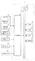
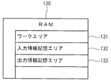
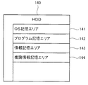
まず、図1乃至図3を参照して、第1の実施の形態に係る推論情報作成装置1の構成について説明する。図1は、推論情報作成装置1の構成を示すブロック図である。図2は、推論情報作成装置1のRAM130の記憶エリアの構成を示す概念図である。図3は、推論情報作成装置1のHDD140の記憶エリアの構成を示す概念図である。
First, with reference to FIG. 1 thru | or FIG. 3, the structure of the inference
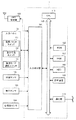
図1に示すように、推論情報作成装置1には、推論情報作成装置1の制御を司るCPU110が設けられている。このCPU110には、バス115を介し、CPU110が実行するBIOS等のプログラムを記憶したROM120と、データを一時的に記憶するRAM130と、データの記憶装置であるハードディスクドライブ(以下、「HDD」という。)140とが接続されている。また、現在日時や時間間隔をカウントするための計時装置190が、バス115を介してCPU110に接続されている。計時装置190は、時計機能を備えたICチップである。また、計時装置190は、インターネットや無線によって日時を取得するように構成してもよい。
As shown in FIG. 1, the inference
また、各種機器からの入力の検知を行う入力検知部180が、バス115を介してCPU110に接続されており、この入力検知部180には、利用者が推論情報作成装置1を操作するためのボタンやスイッチを備えた入力パネル181と、利用者の体温を計測する体温センサ182と、利用者の発汗状態を計測するための発汗センサ183と、利用者の心拍数を計測するための心拍数センサ184とが接続されている。体温センサ182、発汗センサ183及び心拍数センサ184は、有効に利用者の体温、発汗、心拍数を測定できれば、その位置や計測手法は問わないが、好適には、利用者の皮膚にこれらのセンサの読み取り部が設けられている。なお、体温センサ182では計測値として0〜50℃が計測され、発汗センサ183では計測値として0〜100%RHが計測され、心拍数センサ184では計測値として0〜200拍が計測されるものとする。
In addition, an
各センサは、推論情報作成装置1に電源が投入されて起動されると、自動的に定期的な計測を実行するように制御される。各センサの計測値が、各センサ内部の所定の記憶エリアに保存されて、推論情報作成装置1では入力検知部180を介してこの所定の記憶エリアから最新の計測値が取得される。なお、推論情報作成装置1のRAM130やHDD140にセンサ毎の計測値記憶エリア(図示外)を設けて、各センサの計測値が入力検知部180を介して計測値記憶エリアに保存される一方、推論情報作成装置1ではこの計測値記憶エリアが参照されて最新の計測値が取得されるようにしてもよい。
Each sensor is controlled to automatically perform periodic measurement when the inference
また、入力パネル181には、推論情報作成装置1の電源を入切したり、起動し直すための電源リセットスイッチ151と、利用者がみずからの意思を意図的に入力するために、利用者自身がオン・オフしてスイッチ情報を入力するための意思伝達スイッチ152と、推論情報作成装置1の推論モードを選択するための推論モード選択スイッチ153とが、少なくとも設けられている。
In addition, the
利用者がみずからの意思を意図的に推論情報作成装置1に伝達するために、意思伝達スイッチ152をオン又はオフする。例えば、本実施の形態では、推論情報作成装置1は利用者の「感動」について推論するものであるから、利用者は自分が感動していると判断した場合には意思伝達スイッチ152をオンしてスイッチ情報「ON」を入力し、感動していない場合には意思伝達スイッチ152をオンせずに(オフして)スイッチ情報「OFF」を入力する。
In order for the user to intentionally transmit his / her intention to the inference
このような構成によって、第1の実施の形態の推論情報作成装置1では、体温センサ182,発汗センサ183,心拍数センサ184からのセンサ情報と、意思伝達スイッチ152からのスイッチ情報とに基づいて、利用者に関する推論情報が作成される。なお、本実施の形態の推論情報作成装置1で実行されるモジュールの一つとして、推論情報作成プログラムが実行される。推論情報作成プログラムは、あらかじめHDD140上のプログラム記憶エリア142(図3参照)に記憶されているものとする。また、図示外のCD−ROMドライブ、フロッピー(登録商標)ディスクドライブ、各種インタフェースを介して、導入時に、CD−ROM等の外部の記憶媒体やネットワークを介して外部の記憶装置から、HDD140上のプログラム記憶エリア142や情報記憶エリア143(図3参照)に、推論情報作成プログラムがセットアップされてもよい。
With this configuration, the inference
なお、体温センサ182,発汗センサ183,心拍数センサ184からの計測される情報(計測値)が、本発明の「計測値」に相当し、利用者自身が意思伝達スイッチ152をオン・オフして入力するスイッチ情報が、本発明の「利用者入力情報」に相当する。
The information (measurement value) measured from the
図2に示すように、推論情報作成装置1のRAM130には、プログラムの実行中の一時的なデータを記憶するワークエリア131と、入力された各種情報を一時的に記憶する入力情報記憶エリア132と、出力すべき各種情報を一時的に記憶する出力情報記憶エリア133とが設けられている。さらに、RAM130には、図示外の各種記憶エリアが設けられている。
As shown in FIG. 2, the
図3に示すように、推論情報作成装置1のHDD140には、推論情報作成装置1の動作を制御するためCPU110が実行する各種のプログラム等を記憶したオペレーティングシステム(OS)記憶エリア141と、推論情報作成装置1で実行される各種のプログラムや推論情報作成プログラムを記憶したプログラム記憶エリア142と、プログラムの実行に必要な設定や初期値、データ等の情報を記憶した情報記憶エリア143と、作成された推論情報を記憶する推論情報記憶エリア144とが設けられている。なお、情報記憶エリア143には、各種センサから計測された情報に基づいて推論データを作成するための、後述の推論定義テーブルや補正テーブルが記憶されている。また、プログラム記憶エリア142には、複数の推論モードの各々に対応する複数の推論エンジンが、推論情報作成プログラムの一部として記憶されている。
As shown in FIG. 3, the
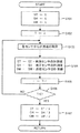
以下、本発明の推論情報作成装置1での処理の流れを、図4乃至図17を参照して説明する。図4は、推論情報作成処理のメインフローチャートである。図5は、推論エンジン初期化処理(S1)の詳細を示すフローチャートである。図6乃至図15は、各推論データ作成処理を説明するための図である。図16は、推論情報出力処理(S11)の詳細を示すフローチャートである。図17は、推論情報10のデータ構成を示す図である。
Hereinafter, the flow of processing in the inference
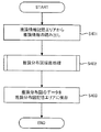
図4に示す推論情報作成処理のメインフローチャートは、利用者が電源リセットスイッチ151(図1参照)を操作して、推論情報作成装置1の電源がオンされた場合、又は推論情報作成装置1のリセットがなされた場合に、その処理が開始される。
The main flowchart of the inference information creation process shown in FIG. 4 is the case where the user operates the power reset switch 151 (see FIG. 1) to turn on the inference
図4に示すように、まず、推論エンジン初期化処理(S1)が実行される。推論エンジン初期化処理は、後述の推論データ作成処理の際に参照される各センサ毎の基準値を初期化する処理である。 As shown in FIG. 4, first, an inference engine initialization process (S1) is executed. The inference engine initialization process is a process for initializing a reference value for each sensor that is referred to in the later-described inference data creation process.
図5に示すように、推論エンジン初期化処理(S1)では、変数ST,変数SH,変数SMにそれぞれ「0」が代入され(S101)、変数Tに「3」が代入される(S102)。そして、各センサから計測値が取得される(S103)。すなわち、体温センサ182,発汗センサ183,心拍数センサ184によって、利用者の体温,発汗,心拍数が計測されて、これらセンサから計測値が各々取得される。
As shown in FIG. 5, in the inference engine initialization process (S1), “0” is assigned to the variable ST, variable SH, and variable SM (S101), and “3” is assigned to the variable T (S102). . And a measured value is acquired from each sensor (S103). That is, the
各センサから取得された体温,発汗,心拍数の各計測値が、それぞれ変数ST,変数SH,変数SMに加算される(S104)。なお、S103による計測値の取得が1回目であれば、S102により変数ST,変数SH,変数SMには「0」が代入されているため、S103により取得された体温,発汗,心拍数の各計測値が、そのまま変数ST,変数SH,変数SMに代入される。 The measured values of body temperature, sweating, and heart rate acquired from each sensor are added to the variable ST, variable SH, and variable SM, respectively (S104). If the measurement value is acquired for the first time in S103, since “0” is substituted for the variable ST, variable SH, and variable SM in S102, each of the body temperature, sweating, and heart rate acquired in S103 is obtained. The measured value is directly substituted into the variable ST, variable SH, and variable SM.
そして、変数Tが「1」減算されて(S105)、Tが「0」でなければ(S106:NO)、S103に戻り、再び各センサによる計測値が取得される。このように、S102で変数Tに設定された回数(ここでは3回)に至るまで、S103の計測値の取得が実行されて、S103〜S106の処理が繰り返される。その結果、変数ST,変数SH,変数SMには、変数Tに設定された回数分の計測値の合計値が記憶される。 Then, the variable T is decremented by “1” (S105), and if T is not “0” (S106: NO), the process returns to S103, and the measurement values obtained by the sensors are acquired again. In this way, until the number of times set to the variable T in S102 (here, 3 times) is reached, the measurement value acquisition in S103 is executed, and the processing in S103 to S106 is repeated. As a result, the variable ST, the variable SH, and the variable SM store the total value of the measurement values for the number of times set in the variable T.
変数ST,変数SH,変数SMは、変数Tに設定された値である「3」で各々除算されて、それぞれ変数CT,変数CH,変数CMに代入される(S107)。すなわち、各センサ毎の計測値の合計値を、その計測回数で除算することで、各センサの1回の計測値の平均値(=平常時の基準値)が取得される。 The variable ST, variable SH, and variable SM are respectively divided by “3”, which is the value set in the variable T, and assigned to the variable CT, variable CH, and variable CM, respectively (S107). That is, by dividing the total value of the measured values for each sensor by the number of times of measurement, an average value (= normal reference value) of one measured value of each sensor is obtained.
変数CTは体温センサ182の基準値であり、変数CHは発汗センサ183の基準値であり、変数CMは心拍数センサ184の基準値である。これらの各センサの基準値は、RAM130に設けられた基準値エリア(図示外)に保存される。
The variable CT is a reference value for the
図4に戻り、推論モードの選択が実行される(S2)。推論情報作成装置1では複数の推論モードから任意のものを選択可能であり、各推論モードによって推論データを作成するための処理内容が異なる。各推論モードに対応する推論エンジンがプログラム記憶エリア142に記憶されており、S2で選択された推論モードに従って、後述の推論データ作成処理を実行する推論エンジンが決定される。
Returning to FIG. 4, the selection of the inference mode is executed (S2). The inference
推論モードの選択(S2)は、利用者が推論モード選択スイッチ153(図1参照)から任意のものを選択することにより実行される。また、推論情報作成装置1において推論モードがあらかじめ設定されている場合は、その設定済みの推論モードが自動的に読込まれて選択される。利用者による推論モードの選択がない場合は、自動的にデフォルトの推論モードが設定される。
The selection of the inference mode (S2) is executed when the user selects an arbitrary one from the inference mode selection switch 153 (see FIG. 1). If the inference mode is set in advance in the inference
次に、S2で選択された推論モードに従って、以降の推論データ作成処理での処理内容が決定される(S3)。本実施の形態においては、「センサ出力モード1」(S4),「センサ出力モード2」(S5),「スイッチ出力モード」(S6),「スイッチ優先モード」(S7),「スイッチ補正モード1」(S8),「スイッチ補正モード2」(S9),「スイッチ状態補正モード」(S10)のいずれかの推論モードが推論データ作成処理として実行される。
Next, according to the inference mode selected in S2, the processing content in the subsequent inference data creation processing is determined (S3). In the present embodiment, “
推論データ作成処理は、センサから計測された情報と利用者が入力した情報とから推論データを作成する処理である。この推論データ作成処理の流れを、推論モードごとに図面を参照して説明する。図6は、「センサ出力モード1」(S4)の詳細を示すフローチャートである。図7は、センサ計測値による推論実行処理(S111,S122,S143,S151,S164,S171)の詳細を示すフローチャートである。図8は、推論定義テーブル13のデータ構成を示す図である。図9は、「センサ出力モード2」(S5)の詳細を示すフローチャートである。図10は、「スイッチ出力モード」(S6)の詳細を示すフローチャートである。図11は、「スイッチ優先モード」(S7)の詳細を示すフローチャートである。図12は、「スイッチ補正モード1」(S8)の詳細を示すフローチャートである。図13は、「スイッチ補正モード2」(S9)の詳細を示すフローチャートである。図14は、「スイッチ状態補正モード」(S10)の詳細を示すフローチャートである。図15は、補正テーブル14のデータ構成を示す図である。
The inference data creation process is a process for creating inference data from information measured from a sensor and information input by a user. The flow of the inference data creation process will be described for each inference mode with reference to the drawings. FIG. 6 is a flowchart showing details of the “
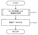
まず、「センサ出力モード1」(S4)は、利用者が意思伝達スイッチ152をオン・オフしたスイッチ情報を考慮せずに、各センサからの計測値のみに基づいて推論データを作成する推論モードである。図6に示すように、「センサ出力モード1」(S4)では、センサ計測値による推論実行処理が実行される(S111)。そして、S111で取得される推論種別及び推論値を含む推論データが作成される(S112)。
First, “
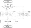
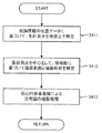
図7に示すように、センサ計測値による推論実行処理(S111)では、体温センサ182,発汗センサ183,心拍数センサ184の各センサで計測された利用者の体温,発汗,心拍数の計測値が、各々取得される(S201)。次に、各センサからの計測値の状態変化を示すフラグである状態変数がクリアされる(S202)。本実施の形態では、体温センサ182が計測する体温についての第2bit、発汗センサ183が計測する発汗についての第1bit、心拍数センサ184が計測する心拍数についての第0bit、の3つのビットを状態変数として有している。そして、RAM130の基準値エリア(図示外)を参照して、S107(図5参照)で算出された各センサの基準値に基づいて、各センサからの計測値の変化を判定する。
As shown in FIG. 7, in the inference execution process (S111) based on the sensor measurement values, the measured values of the body temperature, sweating, and heart rate of the user measured by the
最初に、体温センサ182から取得された体温計測値と、体温に関する基準値(体温閾値)とが比較される(S203)。基準値(閾値)は、RAM130の基準値エリア(図示外)に保存された値である。その結果、体温計測値が体温閾値よりも大きければ(S203:YES)、第2bitが「UP」にセットされる(S204)。一方、体温計測値が体温閾値よりも大きくない場合(S203:NO)、そのまま次のステップ(S205)へ進む。同様に、発汗センサ183から取得された発汗計測値と、発汗に関する基準値(発汗閾値)とが比較され(S205)、その結果、発汗計測値が発汗閾値よりも大きければ(S205:YES)、第1bitが「UP」にセットされる(S206)。一方、発汗計測値が発汗閾値よりも大きくない場合(S205:NO)、そのまま次のステップ(S207)へ進む。また、心拍数センサ184から取得された心拍数計測値も、心拍数に関する基準値(心拍数閾値)と比較され(S207)、その結果、心拍数計測値が心拍数閾値よりも大きければ(S207:YES)、第0bitが「UP」にセットされる(S208)。一方、心拍数計測値が心拍数閾値よりも大きくない場合(S207:NO)、そのまま次のステップ(S209)へ進む。
First, the body temperature measurement value acquired from the
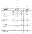
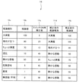
その後、状態変数の第2bit,第1bit,第0bitまでのパターンに対応する推論種別及び推論値が、推論定義テーブル13から取得される(S209)。図8に示すように、推論定義テーブル13は、推論の種別を示す推論種別13aと、各センサからの計測値の変化状態を示すセンサ状態13bと、利用者の推論の強弱を数値で示す推論値13cとをデータ項目として具備している。そして、各々のデータ項目の対応を、テーブル形式で定義している。先述のように、本実施の形態では利用者の「感動」に関する推論データが作成されるから、参照される推論定義テーブル13も「感動」に関するものである。よって、その推論種別13aは「感動」に関する種別が定義されており、利用者の「感動」の強弱によって「大興奮」から「無感動(平常)」までの複数の種別が存在している。また、その「感動」の強弱を数値で表した推論値13cが定義され、例えば、推論種別13aが「大興奮」であれば、その推論値13cは最大値の「100」である。なお、図8に示す推論定義テーブル13は「感動」に関するものであるから、推論値13cは感動度(E)とも表示される。そして、S209では、S203〜S208によりセットされた状態変数によってセンサ状態13bが特定されるから、このセンサ状態13bに対応する推論種別13aや推論値13cが取得される。
Thereafter, inference types and inference values corresponding to the patterns of the second bit, the first bit, and the 0th bit of the state variable are acquired from the inference definition table 13 (S209). As shown in FIG. 8, the inference definition table 13 includes an
次に、「センサ出力モード2」(S5)は、利用者が意思伝達スイッチ152をオンしてスイッチ情報「ON」が入力された場合に、各センサからの計測値に基づいて推論データを作成する推論モードである。
Next, in the “
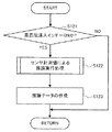
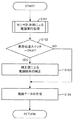
図9に示すように、「センサ出力モード2」(S5)では、意思伝達スイッチ152が「ON」か否かが判定される(S121)。意思伝達スイッチ152が「ON」であれば(S121:YES)、センサ計測値による推論実行処理(S122)が実行される。なお、S122は図7と同一処理である。そして、S122で取得された推論種別13a及び推論値13cを含む推論データが作成される(S123)。一方、意思伝達スイッチ152が「OFF」であれば(S121:NO)、推論データは作成せずに図4に戻る。
As shown in FIG. 9, in “
次に、「スイッチ出力モード」(S6)は、各センサからの計測値を考慮せずに、利用者が意思伝達スイッチ152をオン・オフしたスイッチ情報のみに基づいて推論データを作成する推論モードである。
Next, the “switch output mode” (S6) is an inference mode in which inference data is created based only on switch information that the user turns on / off the
図10に示すように、「スイッチ出力モード」(S6)では、意思伝達スイッチ152が「ON」か否かが判定される(S131)。意思伝達スイッチ152が「ON」であれば(S131:YES)、推論定義テーブル13において、状態変数の第2bit〜第0bitの全てが「UP」であるセンサ状態13bに対応する推論種別13aと推論値13cが取得される(S132)。すなわち、状態変数の第2bit〜第0bitの全てが「UP」である場合、このセンサ状態13bに対応する推論種別13a「大興奮」であり、推論値13c「100」である。これに基づいて、利用者が最も強い「感動」を示した推論データが作成される(S134)。一方、意思伝達スイッチ152が「OFF」であれば(S131:NO)、推論定義テーブル13において、状態変数の第2bit〜第0bitの全てが「UP」でないセンサ状態13bに対応する推論種別13aと推論値13cが取得される(S133)。すなわち、状態変数の第2bit〜第0bitの全てが「UP」でない場合、このセンサ状態13bに対応する推論種別13a「無感動(平常)」であり、推論値13c「0」である。これに基づいて、利用者が最も弱い「感動」を示した推論データが作成される(S134)。
As shown in FIG. 10, in the “switch output mode” (S6), it is determined whether or not the
次に、「スイッチ優先モード」(S7)は、利用者が意思伝達スイッチ152をオンしてスイッチ情報「ON」が入力された場合は、利用者のスイッチ情報に基づいて推論データを作成する一方、利用者が意思伝達スイッチ152をオンせずに(オフして)スイッチ情報「OFF」が入力された場合は、各センサからの計測値に基づいて推論データを作成する推論モードである。
Next, in the “switch priority mode” (S7), when the user turns on the
図11に示すように、「スイッチ優先モード」(S7)では、意思伝達スイッチ152が「ON」か否かが判定される(S141)。意思伝達スイッチ152が「ON」であれば(S141:YES)、推論定義テーブル13において、状態変数の第2bit〜第0bitの全てが「UP」であるセンサ状態13bに対応する推論種別13aと推論値13cが取得される(S142)。一方、意思伝達スイッチ152が「OFF」であれば(S141:NO)、センサ計測値による推論実行処理(S143)が実行される。なお、S143は図7と同一処理である。そして、S142又はS143で取得された推論種別13a及び推論値13cを含む推論データが作成される(S144)。
As shown in FIG. 11, in the “switch priority mode” (S7), it is determined whether or not the
次に、「スイッチ補正モード1」(S8)は、各センサからの計測値に基づいて推論した後に、利用者が意思伝達スイッチ152をオンしてスイッチ情報「ON」が入力されている場合は、所定の補正値により推論結果を補正して推論データを作成する一方、利用者が意思伝達スイッチ152をオンせずに(オフして)スイッチ情報「OFF」が入力されている場合は、推論結果をそのまま推論データとして出力する推論モードである。
Next, in the “
図12に示すように、「スイッチ補正モード1」(S8)では、計測値による推論実行処理(S151)が実行される。なお、S151は図7と同一処理である。そして、意思伝達スイッチ152が「ON」か否かが判定される(S152)。意思伝達スイッチ152が「ON」であれば(S152:YES)、あらかじめ定められた補正値によってS151の推論結果が補正される(S153)。例えば、補正値α=20である場合、S151で取得された推論種別13a「静かな感動」及び推論値13c「50」とすると、推論値13c「50」に補正値α=20が加算されて、推論種別13a「ちょっと興奮」及び推論値13c「70」に推論結果が補正される。そして、この補正後の推論種別13a及び推論値13cを含む推論データが作成される(S154)。一方、意思伝達スイッチ152が「OFF」であれば(S152:NO)、S151で取得された推論種別13a及び推論値13cをそのまま含む推論データが作成される(S154)。なお、補正値αは、意思伝達スイッチ152がオンされた効果を大きく反映させる値であればよく、例えば、推論値13cの30%に相当する値が設定されるようにしてもよい。
As shown in FIG. 12, in the “
次に、「スイッチ補正モード2」(S9)は、各センサから計測値を取得した後、利用者が意思伝達スイッチ152をオンしてスイッチ情報「ON」が入力されている場合は、所定の補正値により各センサの計測値を補正して、この補正後のセンサ計測値による推論実行処理を実行する一方、利用者が意思伝達スイッチ152をオンせずに(オフして)スイッチ情報「OFF」を入力した場合は、通常のセンサ計測値による推論実行処理を実行して、推論データを作成する推論モードである。
Next, in the “
図13に示すように、「スイッチ補正モード2」(S9)では、図7のS201と同様に、各センサからの計測値の取得が実行される(S161)。次に、意思伝達スイッチ152が「ON」か否かが判定される(S162)。意思伝達スイッチ152が「ON」であれば(S162:YES)、あらかじめ定められた補正値によってS161で取得された各センサ計測値が補正される(S163)。補正値は各センサごとにあらかじめ定められており、この補正処理は各センサの計測値ごとに実行される。例えば、体温計測値「36℃」に対しては体温補正値「1℃」が加算されて体温計測値「37℃」に補正され、同様に、発汗計測値は発汗補正値により補正され、心拍数計測値は心拍数補正値により補正される。そして、この補正後の各センサ計測値による推論実行処理が実行される(S164)。一方、意思伝達スイッチ152が「OFF」であれば(S162:NO)、S161で取得された各センサ計測値による推論処理が実行される(S164)。なお、S164は図7と同一処理であるが、各センサからの計測値の取得(S201)は実行されない。そして、S164で取得された推論種別13a及び推論値13cを含む推論データが作成される(S165)。
As shown in FIG. 13, in “
次に、「スイッチ状態補正モード」(S10)は、各センサからの計測値に基づいて推論した後に、利用者が意思伝達スイッチ152をオンしてスイッチ情報「ON」が入力されている場合は、補正テーブル14に定義された補正値により推論結果を補正して推論データを作成する一方、利用者が意思伝達スイッチ152をオンせずに(オフして)スイッチ情報「OFF」が入力されている場合は、推論結果をそのまま推論データとして出力する推論モードである。
Next, in the “switch state correction mode” (S10), after inferring based on the measured values from the sensors, the user turns on the
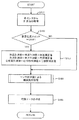
図14に示すように、「スイッチ状態補正モード」(S10)は、図12に示す「スイッチ補正モード1」(S8)と基本的に同じである。ただし、図12ではあらかじめ補正値が定められているのに対し、図14では補正テーブル14を参照して補正値を設定する点で異なる(S173)。
As shown in FIG. 14, the “switch state correction mode” (S10) is basically the same as the “
図15に示すように、補正テーブル14は、補正対象の推論種別14a及び推論値14b、補正対象に加算される補正値であるスイッチON時補正値14c、その補正後の推論種別14d及び推論値14eとから構成されている。S173では、S171で取得された推論種別13a及び推論値13cに基づいて、補正テーブル14で対応する推論種別14a及び推論値14bが検索される。そして、この推論種別14a及び推論値14bに対応するスイッチON時補正値14cが取得される。このスイッチON時補正値14cにより補正される結果、補正後の推論種別14d及び推論値14eが取得される。例えば、S171で推論種別14a「静かな感動」及び推論値14b「50」が取得された場合に、利用者が意思伝達スイッチ152をオンしていれば、補正テーブル14からスイッチON時補正値14c「20」が取得されて、その補正後は推論種別14d「ちょっと興奮」及び推論値14e「70」となる。
As shown in FIG. 15, the correction table 14 includes an
以上、S3において選択された推論モードに従って、CPU110により各推論エンジンが実行されて、各推論データ作成処理(S4,S5,S6,S7,S8,S9,S10)のいずれかが実行されて推論データが作成される。
As described above, according to the inference mode selected in S3, each inference engine is executed by the
このように、複数の推論モードを設けて、利用者が推論モード選択スイッチ153から任意の推論モードを選択できるため、推論情報作成装置1の利用状況や利用環境等に応じて、最適な推論モードによって推論データを作成できる。例えば、利用者が入力したスイッチ情報に基づいて推論情報10を作成したい場合は「スイッチ出力モード」(S6)、各センサからの計測値に基づいて推論情報10を作成したい場合は「センサ出力モード1」(S4)、利用者が入力したスイッチ情報に基づいて推論情報10を補正したい場合は「スイッチ補正モード1」(S8)など、様々な態様が可能である。よって、より正確に利用者に関する推論データを作成することができる。
As described above, since a plurality of inference modes are provided and the user can select an arbitrary inference mode from the inference
また、利用者が意思伝達スイッチ152をオンしてスイッチ情報「ON」が入力されている場合は、推論された感情や意識等が強いことを示す推論データを出力されるような推論モードを設けて、利用者自身が入力した情報を推論データに反映させている。
In addition, when the user turns on the
例えば、「スイッチ出力モード」(S6)では、スイッチ情報「ON」の場合には、利用者が最も強い「感動」を示した推論データが作成される。また、「スイッチ補正モード1」(S8)では、スイッチ情報「ON」の場合には、補正値が推論結果に加算されて、利用者がより「感動」を示した推論データが作成される。よって、例えば、利用者自身が「感動」していると認識して即座に意思伝達スイッチ152をオンした場合は利用者が強く「感動」したことを示す推論データが作成される。このように、利用者自身が「感動」について入力したスイッチ情報を、推論データに反映させることができるようにしている。
For example, in the “switch output mode” (S6), in the case of the switch information “ON”, inference data indicating the strongest “impression” by the user is created. Further, in the “
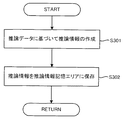
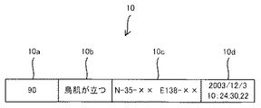
図4に戻り、各推論データ作成処理で作成された推論データを出力する推論情報出力処理(S11)が実行される。図16で示すように、推論情報出力処理(S11)では、各推論データ作成処理で作成された推論データに基づいて、推論情報が作成される(S301)。図17に示すように、推論情報10には、少なくとも推論値10aと推論種別10bとが含まれている。推論値10aと推論種別10bは、推論データに含まれる推論値13c及び推論種別13aに各々対応している。S301で作成された推論情報10は、HDD140の推論情報記憶エリア144(図3参照)に保存される(S302)。
Returning to FIG. 4, an inference information output process (S11) for outputting the inference data created in each inference data creation process is executed. As shown in FIG. 16, in the inference information output process (S11), inference information is created based on the inference data created in each inference data creation process (S301). As shown in FIG. 17, the
その後、図4に戻り、所定時間が経過したか否かが判定される(S12)。この所定時間は、あらかじめ計時装置190にセットされている時間であり、S12では計時装置190を参照して、所定時間の経過が判定される。計時装置190にセットされる所定時間は、利用者又は設計者によって任意の時間を設定可能である。
Thereafter, returning to FIG. 4, it is determined whether or not a predetermined time has passed (S12). This predetermined time is a time set in advance in the
そして、所定時間が経過していなければ(S12:NO)、意思伝達スイッチ152が「ON」か否かを判定される(S13)。意思伝達スイッチが「ON」でない、すなわち「OFF」である場合には(S13:NO)、S12に戻る。よって、所定時間が経過するか、意思伝達スイッチ152が「ON」されるまで、S12〜S13の処理が繰り返される。
If the predetermined time has not elapsed (S12: NO), it is determined whether or not the
一方、所定時間が経過した場合(S12:YES)又は意思伝達スイッチ152が「ON」である場合(S13:YES)、S3に戻って推論モードが選択されて、各推論データ作成処理(S4,S5,S6,S7,S8,S9,S10)のいずれかが実行されて推論データが作成され、さらに推論情報10が出力される(S11)。すなわち、推論情報作成装置1では、所定時間毎に又は意思伝達スイッチ152が「ON」される毎に、最新の推論情報10が出力される処理が繰り返される。その結果、HDD140の推論情報記憶エリア144(図3参照)には、利用者に関する複数の推論情報10が時系列に保存される。
On the other hand, when the predetermined time has elapsed (S12: YES) or when the
以上説明したように、第1の実施の形態の推論情報作成装置1によれば、体温センサ182,発汗センサ183,心拍数センサ184の各センサから取得された計測値と、利用者が意思伝達スイッチ152をオン・オフして入力したスイッチ情報とに基づいて推論情報10が作成されるため、より精度の高い推論情報10を作成することができる。すなわち、利用者は任意にスイッチ情報を入力することで、利用者の意識や感情などを推論情報10に反映させることができるので、推論情報10の精度をより向上させることができる。また推論モードを任意に設定できるので、利用者が入力したスイッチ情報を推論情報10に反映させることができる。
As described above, according to the inference
次に、本発明の第2の実施の形態を図面を参照して説明する。第2の実施の形態に係る推論分布図作成システムは、利用者に携行される小型の携帯端末装置である推論情報作成装置と、固定されたコンピュータ機器である推論分布図作成装置とが、ネットワークを介して接続されたシステムである。 Next, a second embodiment of the present invention will be described with reference to the drawings. An inference distribution map creation system according to the second embodiment includes an inference information creation apparatus that is a small portable terminal device carried by a user and an inference distribution map creation apparatus that is a fixed computer device. It is a system connected via
本実施の形態の推論分布図作成システムでは、複数の推論情報作成装置の各々で作成された推論情報が、ネットワークを介して推論分布図作成装置に収集されて、この推論情報に関する分布図が作成される場合を例示する。 In the inference distribution chart creation system of this embodiment, inference information created by each of a plurality of inference information creation apparatuses is collected in the inference distribution chart creation apparatus via a network, and a distribution chart relating to the inference information is created. The case where it is done is illustrated.
まず、図18乃至図20を参照して、第2の実施の形態に係る推論分布図作成システムの構成について説明する。図18は、推論分布図作成システムの全体構成図である。図19は、推論情報作成装置1の他の構成を示すブロック図である。図20は、推論分布図作成装置2の構成を示すブロック図である。
First, the configuration of an inference distribution map creation system according to the second embodiment will be described with reference to FIGS. FIG. 18 is an overall configuration diagram of the inference distribution map creation system. FIG. 19 is a block diagram showing another configuration of the inference
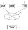
図18に示すように、本実施の形態に係る推論分布図作成システムは、複数の推論情報作成装置1の各々と推論分布図作成装置2とが、ネットワーク90を介して接続されている。ネットワーク90は、有線又は無線を問わず、各々の端末間でデータ送受信可能であるように有効に接続されていればよい。
As shown in FIG. 18, in the inference distribution chart creation system according to the present embodiment, each of a plurality of inference
図19に示すように、推論情報作成装置1の各々は、基本的には第1の実施の形態のもの(図1参照)と同一構成である。しかし、人工衛星からの電波を受信して緯度経度を測定して現在位置を検出するためのGPS受信機185と、外部のネットワーク90と接続するための通信部170とを備える点で異なる。通信部170は、外部のネットワーク90と有線又は無線によって有効に接続できればよいが、例えば、本実施の形態では通信部170は、ネットワーク90と無線LANによる接続を実行するための無線LANアダプタである。
As shown in FIG. 19, each of the inference
図20に示すように、推論分布図作成装置2には、CPU210,ROM220,RAM230,HDD240,ディスプレイ261が接続された表示制御部260,マイク271及びスピーカ272が接続された音声制御部270,マウス281及びキーボード282が接続された入力検知部280が、バス215を介して具備されている。このような推論分布図作成装置2の構成は、通常のコンピュータ機器の構成として公知のものであるから、詳細は省略する。なお、推論分布図作成装置2には、外部のネットワーク90と有線又は無線によって有効に接続するための通信インタフェース291が設けられている。通信インタフェース291はネットワーク90と有効に接続可能であればよいが、例えば、本実施の形態では通信インタフェース291は、有線LANにケーブル接続するためのLANカードである。
As shown in FIG. 20, the inference distribution
以下、本発明の推論分布図作成システムでの処理の流れを、図21乃至図29を参照して説明する。図21は、推論情報作成装置1における、推論情報出力処理(S11)の他の詳細を示すフローチャートである。図22は、推論情報10の他のデータ構成の示す図である。図23は、推論分布図作成装置2における、推論分布図作成処理のメインフローチャートである。図24は、推論分布図作成描画処理(S402)の詳細を示すフローチャートである。図25は、推論分布図の作成過程を説明するための図である。図26は、推論分布図の作成過程を説明するための他の図である。図27は、推論分布図の一例を示す図である。図28は、推論分布図の他の一例を示す図である。図29は、推論分布図の他の一例を示す図である。
The flow of processing in the inference distribution map creation system of the present invention will be described below with reference to FIGS. FIG. 21 is a flowchart showing other details of the inference information output process (S11) in the inference
まず、推論情報作成装置1における処理を説明する。本実施の形態での推論情報作成装置1での処理は、第1の実施の形態における推論情報作成処理(図4)と基本的に同じである。そして、利用者が電源リセットスイッチ151(図1)を操作して、推論情報作成装置1の電源がオンされた場合、又は推論情報作成装置1のリセットがなされた場合に、その処理が開始される点も同じである。しかし、推論情報出力処理(S11)が第1の実施の形態のもの(図16)とは異なる。
First, processing in the inference
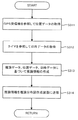
図21に示すように、推論情報出力処理(S11)では、GPS受信機185が参照されて現在位置を示す位置データが取得され(S311)、計時装置190が参照されて現在日時を示す日時データが取得される(S312)。そして、図4に示す各推論データ作成処理(S4,S5,S6,S7,S8,S9,S10)のいずれかで作成された推論データと、S311で取得された位置データと、S312で取得された日時データとに基づいて、推論情報が作成される(S313)。S313で作成された推論情報は、通信部170からネットワーク90を介して、推論分布図作成装置2に送信される(S314)。
As shown in FIG. 21, in the inference information output process (S11), the
図22に示すように、推論情報10には、少なくとも推論値10a,推論種別10b,位置データ10c,日時データ10dが含まれている。推論値10a及び推論種別10bは、推論データに含まれる推論値13c及び推論種別13aに各々対応する。位置データ10cはS311で取得された位置データに、日時データ10dはS312で取得された日時データに、各々対応する。なお、位置データ10cは、絶対座標である必要はなく、相対座標を示すものであってもよい。
As shown in FIG. 22, the
なお、推論分布図作成装置2に送信された推論情報10は、ネットワーク90を介して、通信インタフェース291により受信されて、推論分布図作成装置2のHDD240に設けられた推論情報記憶エリア(図示外)に保存される。
The
次に、推論分布図作成装置2における処理を説明する。推論分布図作成装置2では、推論情報記憶エリア(図示外)に収集された複数の推論情報に基づいて、推論情報に関する分布図を作成する推論分布図作成処理が実行される。推論分布図作成処理は、あらかじめ定められた時間間隔毎に定期的に実行され、又はマウス281やキーボード282から推論分布図が指示されると実行される。
Next, processing in the inference distribution
図23に示すように、推論分布図作成処理では、推論情報記憶エリア(図示外)から分布図の作成対象となる推論情報10が読み出される(S401)。ここで、推論情報記憶エリア(図示外)に保存されている全ての推論情報10を読み出してもよいし、一部のみを読み出してもよい。また、読み出し対象となる推論情報10を、利用者が選択できるようにしてもよい。
As shown in FIG. 23, in the inference distribution map creation process,
次に、S401で読み出された推論情報10に基づいて、推論分布図描画処理(S402)が実行されて、推論情報10に関する分布図である推論分布図が作成される。S402で作成された推論分布図のデータは、HDD240の推論分布図記憶エリア(図示外)に保存される(S403)。
Next, an inference distribution diagram drawing process (S402) is executed based on the
ここで、推論情報10に基づいて分布図を作成する手法としては、各種の分布図作成手法を適用可能であり、どのような手法により推論分布図を作成するかによって、推論分布図作成描画処理(S402)における処理の内容が異なる。ここでは、一例として、同心円状の等高線分布による推論分布図を作成する場合を説明する。
Here, as a method for creating a distribution map based on the
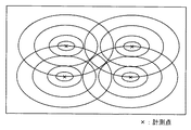
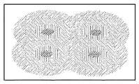
図24に示すように、推論分布図作成描画処理(S402)では、推論情報10に含まれる位置データ10c(図22)に基づいて、各計測点が地図上で特定される(S411)。すなわち、推論情報10の位置データ10cに相当する計測点を、所定の地図上における位置に変換して、その表示位置を特定する。図25は、4つの推論情報10に基づいて推論分布図が作成されており、各推論情報10の計測点が所定の地図上に「×」で特定されていることを示す。
As shown in FIG. 24, in the inference distribution map creation / drawing process (S402), each measurement point is specified on the map based on the
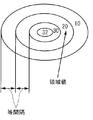
次に、各計測点を中心として、各推論情報10に含まれる推論値10aに基づいて、描画範囲と描画形状が特定される(S412)。図26に示すように、各計測点を中心に同心円(等高線)が描画される範囲や形状が特定されるところ、本実施の形態では、各同心円の間隔は同一であり、また、各同心円には領域値が設定される。領域値は、計測点の推論値10aを頂点として、外側の同心円へ行くほど等間隔に減じた値が設定される。例えば、図26の場合、計測点における推論値10a「32」であるところ、外側の同心円へ行くほど等間隔に「10」減じた領域値が設定されている。このように、S412の描画範囲と描画形状の特定を、全ての計測点について実行する。その結果、図25に示すように、全ての計測点について、同心円状の描画位置及び範囲が特定される。
Next, a drawing range and a drawing shape are specified based on the
最後に、同心円状等高線による分布図の描画処理が実行される(S413)。具体的には、同一の領域値をもつ同心円状の領域を同一色で塗りつぶすように色分け描画される。このような描画処理を領域値の最小値から最大値へ向かう順に、全ての領域値について実行する。その結果、図27に示すように、領域値毎に色分けされた推論分布図が作成される。そして、この推論分布図を参照すれば、複数の利用者がどの領域(エリア)で強い「感動」を感じたのかを把握することができ、逆に、複数の利用者はどの領域(エリア)で「感動」しなかったのか等を、領域値別に把握することができる。 Finally, a distribution map drawing process using concentric contour lines is executed (S413). Specifically, concentric circular regions having the same region value are drawn with different colors so as to be filled with the same color. Such drawing processing is executed for all region values in order from the minimum value to the maximum value of the region values. As a result, as shown in FIG. 27, an inference distribution map that is color-coded for each region value is created. By referring to this inference distribution map, it is possible to grasp in which area (area) a plurality of users felt strong “inspiration”, and conversely, in which area (area) the plurality of users It is possible to ascertain whether or not it was “impressed” by region value.
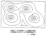
なお、推論分布図作成描画処理(S402)において、次のような推論分布図が作成されてもよい。まず、推論情報10に含まれる位置データ10cに基づいて、その計測点を特定する。次に、推論情報10に含まれる推論値10aを、各計測点での計測値とする。そして、この計測点での計測値を頂点として、計測値の大きさによる等高線表示を行う。すると、図28に示すように、位置データ10cを基準とした推論分布図を作成することができる。
In the inference distribution map creation / drawing process (S402), the following inference distribution map may be created. First, the measurement point is specified based on the
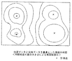
また、推論分布図作成描画処理(S402)において、次のような推論分布図を作成してもよい。まず、推論情報10に含まれる位置データ10cに基づいて、その計測点を特定する。次に、推論情報10に含まれる日時データ10dを元に、各計測点における推論値10aの時間的な変化の大きさを、時間的変化値として求める。そして、この各計測点における時間的変化値の大きさによる等高線表示を行う。すると、図29に示すように、位置データ10cと日時データ10dを基準とした推論分布図を作成することができる。
Further, in the inference distribution map creation / drawing process (S402), the following inference distribution map may be created. First, the measurement point is specified based on the
さらに、推論情報10に利用者の識別情報が含まれていれば、利用者別の複数の推論分布図を作成したり、1つの推論分布図に複数の利用者を区別して表示した推論分布図を作成することができる。
Furthermore, if the
このように、推論分布図作成装置2では、推論分布図作成処理(図23)において、利用者に関する推論分布図が作成される。推論分布図は、利用者の目的や用途に応じて、推論値10a,推論種別10b,位置データ10c,日時データ10dなど、様々な観点から作成可能であり、この推論分布図を様々な分野で利用可能である。
Thus, in the inference distribution
例えば、地震、台風、大雪などの災害が発生した場合、災害発生地域の地図に推論情報10をマッピングすれば、災害発生地域における推論分布図を作成することができる。この推論分布図を参照して、災害発生時の各利用者の感情や意識などの分布を把握したり、心理的な被災状況を把握したりすることができる。また、スタジアムやコンサート会場などで、座席配置図に推論情報10をマッピングすれば、イベント時の各利用者の感情や意識などに分布を把握することができる。
For example, when a disaster such as an earthquake, a typhoon, or heavy snow occurs, an inference distribution map in the disaster occurrence area can be created by mapping the
以上説明したように、第2の実施の形態の推論情報作成装置1によれば、利用者の意識や感情などの推論情報10に関する推論分布図を作成して、推論情報10の分布を把握することができる。
As described above, according to the inference
ところで、上記第1及び第2の実施の形態において、体温センサ182,発汗センサ183,心拍数センサ184からの計測値の入力を検知する入力検知部180(図1)が、本発明の「計測値取得手段」に相当し、意思伝達スイッチ152からのスイッチ情報の入力を検知する入力検知部180(図1)が、本発明の「利用者入力情報取得手段」に相当する。また、各推論データ作成処理(S4,S5,S6,S7,S8,S9,S10)に対応する推論エンジンを実行するCPU110が、本発明の「推論手段」に相当し、推論情報出力処理(S11)を実行するCPU110が、本発明の「推論情報出力手段」に相当する。
By the way, in the first and second embodiments, the input detection unit 180 (FIG. 1) that detects the input of the measurement value from the
また、推論エンジンを複数記憶するプログラム記憶エリア142(図3)が、本発明の「記憶手段」に相当し、推論モード選択スイッチ153が(図1)が、推論手段選択手段に相当する。そして、「センサ出力モード1」(S4)に対応する推論エンジンを実行するCPU110が、本発明の「第1の推論手段」に相当する。「センサ出力モード2」(S5)に対応する推論エンジンを実行するCPU110が、本発明の「第2の推論手段」に相当する。「スイッチ出力モード」(S6)に対応する推論エンジンを実行するCPU110が、本発明の「第3の推論手段」に相当する。「スイッチ優先モード」(S7)に対応する推論エンジンを実行するCPU110が、本発明の「第4の推論手段」に相当する。「スイッチ補正モード1」(S8)又は「スイッチ補正モード2」(S9)に対応する推論エンジンを実行するCPU110が、本発明の「第5の推論手段」に相当する。「スイッチ状態補正モード」(S10)に対応する推論エンジンを実行するCPU110が、本発明の「第6の推論手段」に相当する。なお、GPS受信機185(図19)が、本発明の「位置センサ」に相当する。
The program storage area 142 (FIG. 3) for storing a plurality of inference engines corresponds to the “storage means” of the present invention, and the inference mode selection switch 153 (FIG. 1) corresponds to the inference means selection means. The
また、通信インタフェース291(図20)が、本発明の「推論情報取得手段」に相当し、HDD240に設けられた推論情報記憶エリアが、本発明の「推論情報記憶手段」に相当し、推論分布図作成処理(図23)を実行するCPU210が、本発明の「推論分布図作成手段」に相当する。
The communication interface 291 (FIG. 20) corresponds to the “inference information acquisition unit” of the present invention, the inference information storage area provided in the
なお、本発明は、以上詳述した第1及び第2の実施の形態に限定されるものではなく、各種の変形が可能なことはいうまでもない The present invention is not limited to the first and second embodiments described in detail above, and it goes without saying that various modifications are possible.
例えば、上記実施の形態では、利用者に関する推論情報が「感動」に関する場合を例に説明しているが、推論情報は利用者の意識や感情の他にも、雰囲気や重要度等のように、事象の文脈や状況の前後関係などを示すものであって、事実や証拠のみでは把握できない抽象的な概念(コンテクストともいう。)についての情報であってもよい。そのため、「悲しみ」,「怒り」,「楽しさ」,「賑やかさ」,「忙しさ」等について、推論情報が作成されてもよい。そして、各推論情報の推論内容に対応する推論定義テーブル13が設定されればよい。例えば、利用者の「悲しみ」に基づいて、推論情報を作成したい場合は、「悲しみ」に対応する推論定義テーブル13が設定されればよい。 For example, in the above embodiment, the case where the inference information about the user is related to “impression” has been described as an example. However, the inference information is not only the user's consciousness and emotion but also the atmosphere and the importance level. It may be information about an abstract concept (also referred to as a context) that indicates the context of an event or the context of a situation, and cannot be grasped only by facts and evidence. Therefore, inference information may be created for “sadness”, “anger”, “fun”, “liveness”, “busy”, and the like. Then, an inference definition table 13 corresponding to the inference contents of each inference information may be set. For example, in order to create inference information based on the user's “sadness”, the inference definition table 13 corresponding to “sadness” may be set.
また、推論定義テーブル13には、あらかじめ任意の推論内容についてのテーブルが利用者又は設計者によって設定されていてもよいし、複数の推論内容の各々に対応する複数のテーブルが推論定義テーブル13にあらかじめ設定されており、センサ計測値による推論実行処理(図7)において、自動的に最適なテーブルが選択されるようにしてもよい。 In addition, in the inference definition table 13, a table for arbitrary inference contents may be set in advance by the user or the designer, and a plurality of tables corresponding to each of a plurality of inference contents are included in the inference definition table 13. It may be set in advance, and an optimal table may be automatically selected in the inference execution process based on sensor measurement values (FIG. 7).
また、推論エンジン初期化処理(図5)では、サンプリング値を測定してその平均値を基準値として算定しているが、サンプリング値の時系列データを取得して、その推移の特徴に基づいて基準値を算定するようにしてもよい。また、異常なサンプリング値は除外して基準値を算定するようにしてもよい。また、センサ計測値による推論実行処理(図7)での比較処理(S203,S205,S207)では、各センサ毎に変化閾値εを設けておき、閾値を変化閾値εで補正した補正値で、各センサからの計測値との比較を実行してもよい。例えば、変化閾値εを誤差許容範囲として、閾値の5%程度を設定する等である。また、本実施の形態では、各センサからの計測値を閾値と比較して状態変化を判定しているが、各センサからの計測値から所定の基準値を減算して増分値を求めて、この増分値が閾値よりも大か小かを比較して状態変化を判定するようにしてもよい。 In addition, in the inference engine initialization process (FIG. 5), the sampling value is measured and the average value is calculated as the reference value. However, the time series data of the sampling value is obtained, and based on the characteristics of the transition. The reference value may be calculated. Further, the reference value may be calculated by excluding abnormal sampling values. Further, in the comparison process (S203, S205, S207) in the inference execution process (FIG. 7) based on the sensor measurement value, a change threshold value ε is provided for each sensor, and the correction value is obtained by correcting the threshold value with the change threshold value ε. You may perform a comparison with the measured value from each sensor. For example, about 5% of the threshold is set with the change threshold ε as an allowable error range. Further, in the present embodiment, the state change is determined by comparing the measured value from each sensor with a threshold value, but a predetermined reference value is subtracted from the measured value from each sensor to obtain an increment value, The state change may be determined by comparing whether the increment value is larger or smaller than a threshold value.
また、利用者から入力される情報としては、意思伝達スイッチ152からのスイッチ情報に限定されず、入力パネルやキーボードからの文字入力及びコマンド入力や、マウスによるメニュー画面からの選択など、様々な手段が適用可能である。すなわち、利用者が自らの意思で所定の情報を入力伝達できる手段であればよい。
Also, the information input from the user is not limited to the switch information from the
また、各センサからの計測値は、体温、発汗及び心拍数に限定されないことはいうまでもない。例えば、利用者の振動、脳波、呼吸、加速度、傾き、バイオリズムなどを利用者から計測するようにしてもよい。さらに、各センサ(体温センサ182,発汗センサ183,心拍数センサ184)や入力パネル181は、推論情報作成装置1に一体として構成されている必要はなく、USBやネットワークなどのインタフェースを介して入力検知部180に遠隔接続して、有効に計測値や入力情報を取得できればよい。
Needless to say, the measured values from each sensor are not limited to body temperature, sweating and heart rate. For example, the vibration, brain wave, respiration, acceleration, inclination, biorhythm, etc. of the user may be measured from the user. Further, each sensor (
また、推論分布図作成システムにおいて、推論情報作成装置1はGPS受信機185を利用して位置データを取得しているが、現在位置を有効に特定できれば、他の方法によって位置データを取得してもよい。例えば、推論情報作成装置1にRFIDシステムの質問機(RFIDタグリーダ)を具備させて、所定のリクエストを発することで近傍の応答機(RFIDタグ)から位置データを取得するようにしてもよい。また、推論情報作成装置1に超音波発振/受信機を設けて、位置が既知である基準物体に対して所定の発振を行い、その基準物体からの反射を受信したら、往波復波の時間差を演算して基準位置との差を取得し、その差から位置情報を取得してもよい。
In addition, in the inference distribution map creation system, the inference
また、推論分布図作成システムに推論分布図作成装置2を複数設けてもよい。また、推論情報作成装置1と推論分布図作成装置2とが一体として構成された装置としてもよい。逆に、推論情報作成装置1が1つであってもよい。また、推論分布図作成装置2はディスプレイ261,マイク271,スピーカ272,マウス281,キーボード282は必ずしも必要な構成ではないため、USBやネットワークなどのインタフェースを介して、外部の表示装置,マイク,スピーカなどと遠隔接続してリモート制御するようにしてもよい。
A plurality of inference distribution
本発明の推論情報作成装置、推論分布図作成システム及び推論情報作成プログラムは、利用者の意識や感情などを推論するためのコンピュータ機器に適用できる。 The inference information creation apparatus, the inference distribution map creation system, and the inference information creation program of the present invention can be applied to a computer device for inferring user's consciousness and emotion.
1 推論情報作成装置
2 推論分布図作成装置
10 推論情報
13 推論定義テーブル
14 補正テーブル
90 ネットワーク
110 CPU
115 バス
120 ROM
130 RAM
140 HDD
151 電源リセットスイッチ
152 意思伝達スイッチ
153 推論モード選択スイッチ
170 通信部
180 入力検知部
181 入力パネル
182 体温センサ
183 発汗センサ
184 心拍数センサ
185 GPS受信機
190 計時装置
210 CPU
215 バス
220 ROM
230 RAM
240 HDD
260 表示制御部
261 ディスプレイ
270 音声制御部
271 マイク
272 スピーカ
280 入力検知部
281 マウス
282 キーボード
291 通信インタフェース
DESCRIPTION OF
115
130 RAM
140 HDD
151
215
230 RAM
240 HDD
260
Claims (16)
利用者自身が操作して情報を入力するための入力手段から、前記利用者が入力した利用者入力情報を取得する利用者入力情報取得手段と、
前記計測値取得手段により取得された前記計測値と、前記利用者入力情報取得手段により取得された前記利用者入力情報とに基づいて、該計測値とは異なる指標値である推論データを作成する推論手段と、
前記推論手段により作成された前記推論データを含む推論情報を出力する推論情報出力手段とを備えることを特徴とする推論情報作成装置。 Measurement value acquisition means for acquiring measurement values from at least one sensor;
User input information acquisition means for acquiring user input information input by the user from input means for the user to operate and input information;
Based on the measurement value acquired by the measurement value acquisition unit and the user input information acquired by the user input information acquisition unit, inference data that is an index value different from the measurement value is created. Inference means,
An inference information creating apparatus comprising: inference information output means for outputting inference information including the inference data created by the inference means.
前記記憶手段に記憶された複数の前記推論手段から、任意の該推論手段を選択するための推論手段選択手段とを備えることを特徴とする請求項1に記載の推論情報作成装置。 Storage means for storing a plurality of inference means for creating the inference data based on the measurement value and the user input information;
The inference information creating apparatus according to claim 1, further comprising: an inference means selection means for selecting an arbitrary inference means from the plurality of inference means stored in the storage means.
前記推論情報出力手段は、前記推論手段により前記推論データが作成された場合、前記位置センサにより検出された前記現在位置に関する位置データを取得して、該位置データを含めて前記推論情報を出力することを特徴とする請求項1乃至10のいずれかに記載の推論情報作成装置。 A position sensor for detecting the current position of the user;
The inference information output means acquires position data relating to the current position detected by the position sensor and outputs the inference information including the position data when the inference data is created by the inference means. The inference information creation device according to any one of claims 1 to 10.
前記推論情報出力手段は、前記推論手段により前記推論データが作成された場合、前記計時手段により計測された前記現在日時に関する日時データを取得して、該日時データを含めて前記推論情報を出力することを特徴とする請求項1乃至11のいずれかに記載の推論情報作成装置。 It has time measuring means to measure the current date and time,
When the inference data is created by the inference means, the inference information output means obtains date / time data related to the current date / time measured by the time measuring means, and outputs the inference information including the date / time data The inference information creation device according to any one of claims 1 to 11, wherein
前記推論情報作成装置は、
前記センサから前記計測値を取得する計測値取得手段と、
前記入力手段から前記利用者入力情報を取得する利用者入力情報取得手段と、
前記計測値取得手段により取得された前記計測値と、前記利用者入力情報取得手段により取得された前記利用者入力情報とに基づいて、該計測値とは異なる指標値である推論データを作成する推論手段と、
前記推論手段により作成された前記推論データを含む推論情報を出力する推論情報出力手段とを備え、
前記推論分布図作成装置は、
前記推論情報作成装置の各々から出力された前記推論情報を、ネットワークを介して取得する推論情報取得手段と、
前記推論情報取得手段により取得された前記推論情報を記憶する推論情報記憶手段と、
前記推論情報記憶手段に記憶された前記推論情報に基づいて、該推論情報に関する分布図である推論分布図を作成する推論分布図作成手段とを備えることを特徴とする推論分布図作成システム。 Create inference information for the user based on measured values acquired from at least one sensor and user input information acquired from an input means for the user to operate and input information An inference information creation system in which an inference information creation device that creates an inference distribution map based on the inference information created by the inference information creation device is connected via a network. ,
The inference information creation device includes:
A measurement value acquisition means for acquiring the measurement value from the sensor;
User input information acquisition means for acquiring the user input information from the input means;
Based on the measurement value acquired by the measurement value acquisition unit and the user input information acquired by the user input information acquisition unit, inference data that is an index value different from the measurement value is created. Inference means,
Inference information output means for outputting inference information including the inference data created by the inference means,
The inference distribution map creation device is:
Inference information acquisition means for acquiring the inference information output from each of the inference information creation devices via a network;
Inference information storage means for storing the inference information acquired by the inference information acquisition means;
An inference distribution map creating system comprising: an inference distribution map creating unit that creates an inference distribution map that is a distribution map related to the inference information based on the inference information stored in the inference information storage unit.
前記推論情報作成装置により出力された前記推論情報に含まれる前記位置データに基づいて、該推論情報に関する分布図である推論分布図を作成する推論分布図作成手段とを備えることを特徴とする推論分布図作成システム。 An inference information creation device according to claim 11;
An inference distribution diagram creating means for creating an inference distribution diagram that is a distribution diagram related to the inference information based on the position data included in the inference information output by the inference information creation device; Distribution chart creation system.
前記推論情報作成装置により出力された前記推論情報に含まれる前記日時データに基づいて、該推論情報に関する分布図である推論分布図を作成する推論分布図作成手段とを備えることを特徴とする推論分布図作成システム。 Inference information creation device according to claim 12,
An inference distribution diagram creating means for creating an inference distribution diagram that is a distribution diagram related to the inference information based on the date and time data included in the inference information output by the inference information creation device; Distribution chart creation system.
少なくとも1個以上のセンサから、計測値を取得する計測値取得手段、
利用者自身が操作して情報を入力するための入力手段から、前記利用者が入力した利用者入力情報を取得する利用者入力情報取得手段、
前記計測値取得手段により取得された前記計測値と、前記利用者入力情報取得手段により取得された前記利用者入力情報とに基づいて、該計測値とは異なる指標値である推論データを作成する推論手段、
前記推論手段により作成された前記推論データを含む推論情報を出力する推論情報出力手段、
として機能させるための推論情報作成プログラム。
Computer
Measurement value acquisition means for acquiring measurement values from at least one sensor;
User input information acquisition means for acquiring user input information input by the user from input means for the user to operate and input information;
Based on the measurement value acquired by the measurement value acquisition unit and the user input information acquired by the user input information acquisition unit, inference data that is an index value different from the measurement value is created. Inference means,
Inference information output means for outputting inference information including the inference data created by the inference means;
Inference information creation program to function as
Priority Applications (4)
| Application Number | Priority Date | Filing Date | Title |
|---|---|---|---|
| JP2004049583A JP2005242541A (en) | 2004-02-25 | 2004-02-25 | Inference information creation device, inference distribution map creation system, and inference information creation program |
| PCT/JP2005/002735 WO2005081185A1 (en) | 2004-02-25 | 2005-02-21 | Inference information preparing device, inference information control system, inference information preparing system, inference information preparingprogram, recording medium recording inference information preparing program computer-readably, and inference information preparing method |
| PCT/JP2005/002736 WO2005081186A1 (en) | 2004-02-25 | 2005-02-21 | Inference information preparing device, inference information preparing system, inference information preparing program and recording medium recording inference information preparing program computer-readably |
| US11/467,056 US20070022074A1 (en) | 2004-02-25 | 2006-08-24 | Inference Information Creating Device |
Applications Claiming Priority (1)
| Application Number | Priority Date | Filing Date | Title |
|---|---|---|---|
| JP2004049583A JP2005242541A (en) | 2004-02-25 | 2004-02-25 | Inference information creation device, inference distribution map creation system, and inference information creation program |
Publications (1)
| Publication Number | Publication Date |
|---|---|
| JP2005242541A true JP2005242541A (en) | 2005-09-08 |
Family
ID=35024243
Family Applications (1)
| Application Number | Title | Priority Date | Filing Date |
|---|---|---|---|
| JP2004049583A Pending JP2005242541A (en) | 2004-02-25 | 2004-02-25 | Inference information creation device, inference distribution map creation system, and inference information creation program |
Country Status (1)
| Country | Link |
|---|---|
| JP (1) | JP2005242541A (en) |
Citations (3)
| Publication number | Priority date | Publication date | Assignee | Title |
|---|---|---|---|---|
| JPH09251069A (en) * | 1996-03-14 | 1997-09-22 | Noboru Akasaka | Whereabouts search system |
| JPH11203006A (en) * | 1998-01-20 | 1999-07-30 | Fujitsu Ltd | User situation estimation device |
| JP2003240320A (en) * | 2002-02-18 | 2003-08-27 | Toshiba Corp | Air conditioning systems and sleep devices |
-
2004
- 2004-02-25 JP JP2004049583A patent/JP2005242541A/en active Pending
Patent Citations (3)
| Publication number | Priority date | Publication date | Assignee | Title |
|---|---|---|---|---|
| JPH09251069A (en) * | 1996-03-14 | 1997-09-22 | Noboru Akasaka | Whereabouts search system |
| JPH11203006A (en) * | 1998-01-20 | 1999-07-30 | Fujitsu Ltd | User situation estimation device |
| JP2003240320A (en) * | 2002-02-18 | 2003-08-27 | Toshiba Corp | Air conditioning systems and sleep devices |
Similar Documents
| Publication | Publication Date | Title |
|---|---|---|
| JP7318641B2 (en) | Program, information processing device, and information processing method | |
| US9024976B2 (en) | Postural information system and method | |
| US11567581B2 (en) | Systems and methods for position-based gesture control | |
| US10542929B2 (en) | Determining conditions based on intraoral sensing | |
| US20100228487A1 (en) | Postural information system and method | |
| US20190377178A1 (en) | Virtual reality system and information processing system | |
| US20100225474A1 (en) | Postural information system and method | |
| JP2005095570A (en) | Image display system, image display apparatus, and image display method | |
| JP7401634B2 (en) | Server device, program and method | |
| CN114097253A (en) | Portable monitoring equipment, remote monitoring center and medical monitoring method | |
| JP5803169B2 (en) | Sleep evaluation apparatus and sleep evaluation method | |
| US10102769B2 (en) | Device, system and method for providing feedback to a user relating to a behavior of the user | |
| JP2020065642A (en) | Program, game server, information processing terminal, method and game system | |
| JP2005253791A (en) | Inference information creation device, inference information creation system, and inference information creation program | |
| WO2005081185A1 (en) | Inference information preparing device, inference information control system, inference information preparing system, inference information preparingprogram, recording medium recording inference information preparing program computer-readably, and inference information preparing method | |
| JP2005275960A (en) | Object identification device, object identification system and popularity voting system | |
| JPWO2020075368A1 (en) | Information processing equipment, information processing methods and programs | |
| CN109907747A (en) | User Status monitoring method, device and wearable device | |
| EP4243686B1 (en) | A method of generating a real time protractor display | |
| JP2018108280A (en) | User terminal device and data transmission method | |
| TWI901802B (en) | Health support device, blood sugar level estimation device, learning device, health support method, and computer program for health support | |
| Torres et al. | Assistive technology for fall detection development of integrated wearable sensor to smart home system | |
| JP7294449B2 (en) | MONITORING SYSTEM, MONITORING METHOD AND MONITORING PROGRAM | |
| US20050052444A1 (en) | Apparatus and method for generating image | |
| US20250318806A1 (en) | Graphical user interface for vascular stent expansion visualization |
Legal Events
| Date | Code | Title | Description |
|---|---|---|---|
| A621 | Written request for application examination |
Free format text: JAPANESE INTERMEDIATE CODE: A621 Effective date: 20070117 |
|
| RD04 | Notification of resignation of power of attorney |
Free format text: JAPANESE INTERMEDIATE CODE: A7424 Effective date: 20080212 |
|
| A131 | Notification of reasons for refusal |
Free format text: JAPANESE INTERMEDIATE CODE: A131 Effective date: 20100420 |
|
| A02 | Decision of refusal |
Free format text: JAPANESE INTERMEDIATE CODE: A02 Effective date: 20100817 |