JP2005246169A - Head unit and mounting method thereof - Google Patents
Head unit and mounting method thereof Download PDFInfo
- Publication number
- JP2005246169A JP2005246169A JP2004057585A JP2004057585A JP2005246169A JP 2005246169 A JP2005246169 A JP 2005246169A JP 2004057585 A JP2004057585 A JP 2004057585A JP 2004057585 A JP2004057585 A JP 2004057585A JP 2005246169 A JP2005246169 A JP 2005246169A
- Authority
- JP
- Japan
- Prior art keywords
- carriage
- sub
- disposed
- head unit
- mounting portion
- Prior art date
- Legal status (The legal status is an assumption and is not a legal conclusion. Google has not performed a legal analysis and makes no representation as to the accuracy of the status listed.)
- Granted
Links
- 238000000034 method Methods 0.000 title claims abstract description 22
- 239000011344 liquid material Substances 0.000 claims description 49
- 238000004519 manufacturing process Methods 0.000 description 10
- 239000007788 liquid Substances 0.000 description 8
- 238000012423 maintenance Methods 0.000 description 7
- 230000015572 biosynthetic process Effects 0.000 description 5
- 239000000463 material Substances 0.000 description 5
- 239000000758 substrate Substances 0.000 description 5
- 239000004973 liquid crystal related substance Substances 0.000 description 3
- 239000002184 metal Substances 0.000 description 3
- 238000006073 displacement reaction Methods 0.000 description 2
- 238000009429 electrical wiring Methods 0.000 description 2
- 238000007689 inspection Methods 0.000 description 2
- 238000009434 installation Methods 0.000 description 2
- 238000003825 pressing Methods 0.000 description 2
- 125000006850 spacer group Chemical group 0.000 description 2
- LFQSCWFLJHTTHZ-UHFFFAOYSA-N Ethanol Chemical compound CCO LFQSCWFLJHTTHZ-UHFFFAOYSA-N 0.000 description 1
- 230000001133 acceleration Effects 0.000 description 1
- 238000013459 approach Methods 0.000 description 1
- QVGXLLKOCUKJST-UHFFFAOYSA-N atomic oxygen Chemical compound [O] QVGXLLKOCUKJST-UHFFFAOYSA-N 0.000 description 1
- 238000005452 bending Methods 0.000 description 1
- 230000037237 body shape Effects 0.000 description 1
- 239000000919 ceramic Substances 0.000 description 1
- 238000004140 cleaning Methods 0.000 description 1
- 238000007599 discharging Methods 0.000 description 1
- 230000000694 effects Effects 0.000 description 1
- 238000005516 engineering process Methods 0.000 description 1
- 239000007789 gas Substances 0.000 description 1
- 239000011521 glass Substances 0.000 description 1
- 230000010365 information processing Effects 0.000 description 1
- 230000003287 optical effect Effects 0.000 description 1
- 239000001301 oxygen Substances 0.000 description 1
- 229910052760 oxygen Inorganic materials 0.000 description 1
- 238000000059 patterning Methods 0.000 description 1
- 238000009832 plasma treatment Methods 0.000 description 1
- 230000001105 regulatory effect Effects 0.000 description 1
- 238000007650 screen-printing Methods 0.000 description 1
- TXEYQDLBPFQVAA-UHFFFAOYSA-N tetrafluoromethane Chemical compound FC(F)(F)F TXEYQDLBPFQVAA-UHFFFAOYSA-N 0.000 description 1
- 239000010409 thin film Substances 0.000 description 1
Images

Landscapes
- Ink Jet (AREA)
- Coating Apparatus (AREA)
Abstract
【課題】 複数の液滴吐出ヘッドを搭載した大型のサブキャリッジを、効率良く運搬且つ取付けすることができるヘッドユニット、およびその取付け方法を提供することにある。
【解決手段】 キャリッジ取付部30の底面の近傍のY軸方向に沿う両側には、ガイドとしての2本のガイドレール(1本は図示せず)33が配設されている。また、ガイドレール33に対して略垂直方向の面にねじ止め用の4個の孔34a,34b,34c,34d(34cおよび34dは図示せず)が配設されている。ガイドレール33のサブキャリッジ50が挿入される一端には、度当たりピン35a,35b(35bは図示せず)が2本のガイドレールのそれぞれに配設されている。また、キャリッジ取付部30のサブキャリッジ50が挿入される反対の面には、コネクタボード固定側36が、キャリッジ取付部30に固定されている。
【選択図】 図3
PROBLEM TO BE SOLVED: To provide a head unit capable of efficiently transporting and mounting a large sub-carriage having a plurality of droplet discharge heads mounted thereon, and a mounting method thereof.
SOLUTION: Two guide rails (one not shown) 33 as guides are disposed on both sides along the Y-axis direction in the vicinity of the bottom surface of the carriage mounting portion 30. Further, four holes 34a, 34b, 34c, 34d (34c and 34d are not shown) for screwing are disposed on a surface substantially perpendicular to the guide rail 33. At one end of the guide rail 33 where the sub-carriage 50 is inserted, pins 35a and 35b (35b not shown) are disposed on each of the two guide rails. A connector board fixing side 36 is fixed to the carriage mounting portion 30 on the opposite surface of the carriage mounting portion 30 where the sub-carriage 50 is inserted.
[Selection] Figure 3
Description
工業用液状材料を吐出し、電気光学装置、電子放出装置等の各種装置を製造する液滴吐出装置(描画装置)のサブキャリッジ取付け方法、取付け機構、電気的配線処理、液状材料に係る配管処理に関する。電気光学装置として、液晶表示装置、有機EL装置、PDP装置、電気泳動表示装置等があり、電子放出装置としてFED装置等がある。また、スペーサ形成、金属配線形成、レンズ形成、レジスト形成および光拡散体形成に関するものである。 Sub-carriage mounting method, mounting mechanism, electrical wiring processing, and piping processing related to liquid materials for droplet discharge devices (drawing devices) that discharge industrial liquid materials and manufacture various devices such as electro-optical devices and electron emission devices About. Examples of the electro-optical device include a liquid crystal display device, an organic EL device, a PDP device, and an electrophoretic display device. Examples of the electron-emitting device include an FED device. The present invention also relates to spacer formation, metal wiring formation, lens formation, resist formation, and light diffuser formation.
従来、大型のプリンタでは、インクジェットヘッド(液滴吐出ヘッド)の歩留まりを考慮し、副走査方向の吐出ノズルの全並び(1ライン)を、単一の液滴吐出ヘッドではなく、複数の液滴吐出ヘッドで構成している。この場合、複数の液滴吐出ヘッドは、単一のキャリッジに搭載され、ヘッドユニットとしてプリンタの駆動系に取り付けられている。 Conventionally, in a large printer, in consideration of the yield of an inkjet head (droplet discharge head), the entire arrangement (one line) of discharge nozzles in the sub-scanning direction is not a single droplet discharge head but a plurality of droplets. It consists of a discharge head. In this case, the plurality of droplet discharge heads are mounted on a single carriage and are attached to a printer drive system as a head unit.
また従来は、液滴吐出装置のキャリッジに取り付けるキャリッジ取付部に、サブキャリッジを取り付ける際に、位置決めピンとそれと勘合する孔で位置決めしていた。そのため、重いサブキャリッジを持ち上げて嵌合させるという上下方向の作業を行っていたため作業効率が良くなかった。また、持上げる際にサブキャリッジに撓みが生ずる等の不具合があった。また、サブキャリッジをキャリッジ取付部に取り付けた後、個別に電気的配線処理、液状吐出材料に係る配管処理を行う必要があった(特許文献1参照)。 Conventionally, when a sub-carriage is attached to a carriage attachment portion attached to a carriage of a droplet discharge device, positioning is performed using a positioning pin and a hole that engages with the positioning pin. For this reason, the work efficiency is not good because the work in the up-and-down direction for lifting and fitting the heavy sub-carriage is performed. In addition, there are problems such as bending of the sub-carriage when lifting. In addition, after the sub-carriage is mounted on the carriage mounting portion, it is necessary to individually perform electrical wiring processing and piping processing related to the liquid discharge material (see Patent Document 1).
ところで、この種の液滴吐出ヘッドは、そのノズル列から微小な液滴を精度良く且つ選択的に吐出することができるため、液晶表示装置や有機EL表示装置等のカラーフィルタの製造に応用可能であると共に、各種の電子デバイスや光デバイス等の製造装置への応用も期待されている。このような応用技術を考慮すると、数多くの液滴吐出ヘッドを単一のサブキャリッジに搭載した大型のヘッドユニットが必要となると同時に、吐出対象となる液体等によっては、液滴吐出ヘッドの耐久性も問題となり、液滴吐出ヘッド(ヘッドユニット)の頻繁な交換も考慮する必要がある。すなわち、従来のものと異なり、頻繁な交換(取付け・取外し)を考慮した重量のある大型のヘッドユニットが必要となることが想定される。 By the way, this type of droplet discharge head can accurately and selectively discharge minute droplets from the nozzle row, and can be applied to the manufacture of color filters such as liquid crystal display devices and organic EL display devices. In addition, it is expected to be applied to manufacturing apparatuses for various electronic devices and optical devices. Considering such applied technology, a large head unit with a large number of droplet discharge heads mounted on a single sub-carriage is required. At the same time, depending on the liquid to be discharged, the durability of the droplet discharge head Therefore, it is necessary to consider frequent replacement of the droplet discharge head (head unit). That is, unlike the conventional one, it is assumed that a large-sized head unit having a heavy weight considering frequent replacement (attachment / removal) is required.
本発明は、複数の液滴吐出ヘッドを搭載した大型のサブキャリッジを、効率良く運搬且つ取付けすることができるヘッドユニット、およびその取付け方法を提供することにある。また、このヘッドユニット、およびその取付け方法を用いて製造する液晶表示装置の製造方法、有機EL装置の製造方法、電子放出装置の製造方法、PDP装置の製造方法、電気泳動表示装置の製造方法、カラーフィルタの製造方法、有機ELの製造方法、スペーサ形成方法、金属配線形成方法、レンズ形成方法、レジスト形成方法および光拡散体形成方法を提供することをその課題としている。 It is an object of the present invention to provide a head unit that can efficiently transport and attach a large sub-carriage having a plurality of droplet discharge heads mounted thereon, and a method for attaching the head unit. Further, a manufacturing method of a liquid crystal display device manufactured using the head unit and its mounting method, a manufacturing method of an organic EL device, a manufacturing method of an electron emission device, a manufacturing method of a PDP device, a manufacturing method of an electrophoretic display device, It is an object to provide a color filter manufacturing method, an organic EL manufacturing method, a spacer forming method, a metal wiring forming method, a lens forming method, a resist forming method, and a light diffuser forming method.
上記課題を解決するため、本発明では、複数の液滴吐出ヘッドと、複数の液滴吐出ヘッドが配設されたサブキャリッジと、サブキャリッジが脱着されるキャリッジ取付部と、サブキャリッジの外形とキャリッジ取付部に配設されたガイドとによって取り付けることを要旨とする。 In order to solve the above problems, in the present invention, a plurality of droplet discharge heads, a sub-carriage provided with a plurality of droplet discharge heads, a carriage mounting portion to which the sub-carriage is attached and detached, and an outer shape of the sub-carriage The gist is to mount the guide by a guide disposed on the carriage mounting portion.
この構成によれば、サブキャリッジの外形とキャリッジ取付部に配設されたガイドとによって、作業者が大型で重いサブキャリッジを上に持上げることをせずに、略水平にサブキャリッジをキャリッジ取付部に載せ込むことことができ、複数の液滴吐出ヘッドを搭載した大型のサブキャリッジを、効率良く取付けすることができる。 According to this configuration, the sub carriage is mounted on the carriage substantially horizontally without lifting up the large and heavy sub carriage by the outer shape of the sub carriage and the guide disposed on the carriage mounting portion. A large-sized sub-carriage having a plurality of droplet discharge heads mounted thereon can be efficiently mounted.
本発明では、ヘッドユニットにおいて、キャリッジ取付部に配設されたガイドの底部上面とサブキャリッジの下面とによって、キャリッジ取付部とサブキャリッジとの鉛直方向の相対位置が決まることを要旨とする。 The gist of the present invention is that, in the head unit, the relative position in the vertical direction between the carriage mounting portion and the sub-carriage is determined by the upper surface of the bottom of the guide disposed on the carriage mounting portion and the lower surface of the sub-carriage.
この構成によれば、キャリッジ取付部に配設されたガイドの底部上面にサブキャリッジの下面が当接して、キャリッジ取付部がサブキャリッジを支えているため、作業者が大型で重いサブキャリッジを上に持上げることをせずに、略水平にサブキャリッジをキャリッジ取付部に載せ込むことことができる。 According to this configuration, the lower surface of the sub carriage is in contact with the upper surface of the bottom of the guide disposed in the carriage mounting portion, and the carriage mounting portion supports the sub carriage. The sub-carriage can be placed on the carriage mounting portion substantially horizontally without being lifted up.
本発明では、ヘッドユニットにおいて、サブキャリッジの一部が、キャリッジ取付部に配設されたガイドの一端部にガイドと略垂直に配設された面に当接して、キャリッジ取付部とサブキャリッジとの相対位置が決まることを要旨とする。 In the present invention, in the head unit, a part of the sub carriage is brought into contact with a surface disposed substantially perpendicular to the guide at one end of the guide disposed in the carriage mounting portion, and the carriage mounting portion, the sub carriage, The gist is that the relative position of is determined.
この構成によれば、サブキャリッジをキャリッジ取付部に配設されたガイドに載せ込み、サブキャリッジの一部がキャリッジ取付部に配設されたガイドと略垂直に配設された面に当接して、サブキャリッジとキャリッジ取付部との相対位置が決まるため、作業者は、キャリッジ取付部にサブキャリッジを押し込んで止まるまで押せば作業を終了することができ効率良く取付けすることができる。 According to this configuration, the sub-carriage is placed on the guide disposed on the carriage mounting portion, and a part of the sub-carriage contacts the surface disposed substantially perpendicular to the guide disposed on the carriage mounting portion. Since the relative position between the sub-carriage and the carriage mounting portion is determined, the operator can complete the work by pressing the sub-carriage into the carriage mounting portion and pressing it until it stops.
本発明では、ヘッドユニットにおいて、サブキャリッジに配設された孔とキャリッジ取付部またはガイドに配設された孔とにピンを通すことによって、キャリッジ取付部とサブキャリッジとの相対位置が決まることを要旨とする。 According to the present invention, in the head unit, the relative position between the carriage mounting portion and the sub-carriage is determined by passing a pin through the hole provided in the sub-carriage and the hole provided in the carriage mounting portion or guide. The gist.
この構成によれば、サブキャリッジに配設された孔とキャリッジ取付部またはガイドに配設された孔とにピンを通すことによって、キャリッジ取付部とサブキャリッジとの相対位置が決まるため、作業者は、サブキャリッジから一旦手を離すことができ、小さなピンを取り付けることによってキャリッジ取付部とサブキャリッジとの相対位置を決めることができるため、効率良く取付けすることができる。 According to this configuration, the relative position between the carriage mounting portion and the sub carriage is determined by passing the pin through the hole disposed in the sub carriage and the hole disposed in the carriage mounting portion or the guide. Can be removed from the sub-carriage once, and the relative position between the carriage attachment portion and the sub-carriage can be determined by attaching a small pin, so that the attachment can be performed efficiently.
本発明では、ヘッドユニットにおいて、サブキャリッジの一面に配設された雌ねじとキャリッジ取付部またはガイドに配設された孔とを使って螺合されて固定されることを要旨とする。 The gist of the present invention is that the head unit is screwed and fixed using a female screw provided on one surface of the sub-carriage and a hole provided in the carriage mounting portion or guide.
この構成によれば、サブキャリッジの一面に配設された雌ねじとキャリッジ取付部またはガイドに配設された孔とを使って螺合されて固定されるため、作業者は、ねじでサブキャリッジとキャリッジ取付部とを止めるだけで固定することができ、効率良く取付けすることができる。 According to this configuration, since the screw is fixed using the female screw provided on one surface of the sub-carriage and the hole provided in the carriage mounting portion or the guide, the operator can connect the sub-carriage with the screw. It can be fixed simply by stopping the carriage mounting portion, and can be mounted efficiently.
本発明では、ヘッドユニットにおいて、サブキャリッジに配設された複数の電気的コネクタとキャリッジ取付部に配設された複数の電気的コネクタとがすべて一度に電気的に接続されることを要旨とする。 The gist of the present invention is that, in the head unit, the plurality of electrical connectors disposed on the sub-carriage and the plurality of electrical connectors disposed on the carriage mounting portion are all electrically connected at once. .
この構成によれば、サブキャリッジに配設された複数の電気的コネクタとキャリッジ取付部に配設された複数の電気的コネクタとの接続を個々に作業することがなくなるとともに、電気的接続作業でのミスが皆無となり、効率良く取付けすることができる。 According to this configuration, it is not necessary to individually connect the plurality of electrical connectors disposed on the sub-carriage and the plurality of electrical connectors disposed on the carriage mounting portion. This eliminates any mistakes and enables efficient installation.
本発明では、ヘッドユニットにおいて、サブキャリッジに配設された複数の液状材料用コネクタとキャリッジ取付部に配設された複数の液状材料用コネクタとが接続されることを要旨とする。 The gist of the present invention is that in the head unit, a plurality of liquid material connectors disposed on the sub-carriage and a plurality of liquid material connectors disposed on the carriage mounting portion are connected.
この構成によれば、サブキャリッジに配設された複数の液状材料用コネクタとキャリッジ取付部に配設された複数の液状材料用コネクタとの接続を個々に作業することがなくなるとともに、液状材料の接続作業でのミスが皆無となり、効率良く取付けすることができる。 According to this configuration, it is not necessary to individually connect the plurality of liquid material connectors disposed on the sub-carriage and the plurality of liquid material connectors disposed on the carriage mounting portion. There are no mistakes in connection work, and it can be installed efficiently.
本発明では、ヘッドユニットにおいて、サブキャリッジに配設された電気的コネクタまたは液状材料用コネクタと、キャリッジ取付部に配設された電気的コネクタまたは液状材料用コネクタとが接触する前に、サブキャリッジまたはキャリッジ取付部に配設された案内ピンの一端が、キャリッジ取付部またはサブキャリッジに配設された案内孔部材の平行孔部の一端に達することを要旨とする。 In the present invention, in the head unit, before the electrical connector or the liquid material connector disposed on the sub-carriage contacts the electrical connector or the liquid material connector disposed on the carriage mounting portion, the sub-carriage Alternatively, the gist is that one end of the guide pin disposed on the carriage mounting portion reaches one end of the parallel hole portion of the guide hole member disposed on the carriage mounting portion or the sub-carriage.
この構成によれば、サブキャリッジに配設された電気的コネクタまたは液状材料用コネクタと、キャリッジ取付部に配設された電気的コネクタまたは液状材料用コネクタとを一度に接続させるために、これらのコネクタが接触する前に、サブキャリッジまたはキャリッジ取付部のいずれかに配設されている案内ピンの一端が、サブキャリッジまたはキャリッジ取付部のいずれかに配設されている案内孔部材の平行孔部の一端に達し、サブキャリッジとキャリッジ取付部との相対位置が、案内ピンと案内孔部材の平行孔部とで決まるため、これらのコネクタの破損を防ぐとともに、効率良く取付けすることができる。 According to this configuration, in order to connect the electrical connector or the liquid material connector disposed in the sub-carriage and the electrical connector or the liquid material connector disposed in the carriage mounting portion at a time, these Before the connector comes into contact, one end of the guide pin disposed on either the sub-carriage or the carriage mounting portion is connected to the parallel hole portion of the guide hole member disposed on either the sub-carriage or the carriage mounting portion. Since the relative position between the sub-carriage and the carriage mounting portion is determined by the guide pin and the parallel hole portion of the guide hole member, these connectors can be prevented from being damaged and mounted efficiently.
本発明では、ヘッドユニットにおいて、サブキャリッジに配設された案内ピンと、キャリッジ取付部に配設された案内孔部材との間に弾性部材が圧縮されて配設されたことを要旨とする。 The gist of the present invention is that in the head unit, an elastic member is compressed and disposed between the guide pin disposed on the sub-carriage and the guide hole member disposed on the carriage mounting portion.
この構成によれば、サブキャリッジに配設された案内ピンと、キャリッジ取付部に配設された案内孔部材との間に弾性部材が圧縮されて配設されているため、サブキャリッジをキャリッジ取付部から取り外す際に、この弾性部材の付勢により作業者が楽に取り外すことができる。 According to this configuration, the elastic member is compressed and disposed between the guide pin disposed on the sub-carriage and the guide hole member disposed on the carriage mounting portion. The operator can easily remove the elastic member by urging the elastic member.
本発明では、サブキャリッジを液滴吐出装置のキャリッジに取り付けられたキャリッジ取付部に取り付けるヘッドユニットの取付け方法であって、サブキャリッジを仮置き台上にいったん載せ、サブキャリッジをキャリッジ取付部のガイドに向かって仮置き台上をスライドさせながら、サブキャリッジの先端部がガイドに案内されて略水平に載せ込むことを要旨とする。 The present invention relates to a head unit mounting method for mounting a sub-carriage to a carriage mounting portion mounted on a carriage of a droplet discharge device, wherein the sub-carriage is temporarily placed on a temporary placement table, and the sub-carriage is guided to the carriage mounting portion. The point is that the tip of the sub-carriage is guided by the guide and is placed almost horizontally while sliding on the temporary placement table.
この構成によれば、サブキャリッジを仮置き台上にいったん載せ、サブキャリッジをキャリッジ取付部のガイドに向かって仮置き台上をスライドさせながら、サブキャリッジの先端部がガイドに案内されて略水平に載せ込むことができるため、サブキャリッジ50を持上げることに起因するサブキャリッジ50自体の撓みを防止し、サブキャリッジ50に装着されている複数の液滴吐出ヘッド51同士の相対位置ずれを防止するとともに、作業者が楽に効率良く取付けすることができる。
According to this configuration, the subcarriage is temporarily placed on the temporary placement table, and while the subcarriage is slid on the temporary placement table toward the guide of the carriage mounting portion, the tip of the subcarriage is guided by the guide and is substantially horizontal. Therefore, it is possible to prevent the
本発明では、ヘッドユニットの取付け方法であって、サブキャリッジに配設された液滴吐出ヘッドのノズル面を下方に向けて、略水平に位置された仮置き台上に取り付け、仮置き台を所望の角度に回動固定してヘッドユニットの調整作業を行い、調整作業が終了した際は仮置き台を略水平の位置に戻すことを要旨とする。 In the present invention, there is provided a method for mounting the head unit, wherein the nozzle surface of the droplet discharge head disposed on the sub-carriage is directed downward and is mounted on a temporary table that is positioned substantially horizontally. The gist of the invention is that the head unit is adjusted by rotating and fixing at a desired angle, and when the adjustment work is completed, the temporary placing table is returned to a substantially horizontal position.
この構成によれば、液滴吐出ヘッドのノズル面を下方に向けて大型のサブキャリッジを略水平に位置された仮置き台上に取り付け、仮置き台を所望の角度に回動固定してヘッドユニットの調整作業を行えるため、サブキャリッジの調整作業が安全に楽にできるとともに、調整作業が終了した際は仮置き台を略水平の位置に戻し、サブキャリッジの向きをキャリッジ取付部への取付け姿勢にすることができるため、調整作業から取付け作業まで一貫して効率良くすることができる。 According to this configuration, the large sub-carriage is mounted on the temporary placement table positioned substantially horizontally with the nozzle surface of the droplet discharge head facing downward, and the temporary placement table is rotated and fixed at a desired angle. Since the unit can be adjusted, the sub-carriage can be adjusted safely and easily. When the adjustment is completed, the temporary table is returned to a substantially horizontal position, and the orientation of the sub-carriage is adjusted to the carriage mounting position. Therefore, from the adjustment work to the installation work can be made consistently and efficiently.
本発明では、ヘッドユニットの取付け方法であって、仮置き台の下方に配設された上下可動部によって仮置き台の高さ調整がなされ、仮置き台の一部またはサブキャリッジの一部が液滴吐出装置のキャリッジの一部またはキャリッジ取付部の一部に当接して仮置き台とキャリッジ取付部との相対位置が決まることを要旨とする。 In the present invention, there is provided a method for mounting the head unit, wherein the height of the temporary table is adjusted by a vertically movable portion disposed below the temporary table, and a part of the temporary table or a part of the sub carriage is provided. The gist is that the relative position between the temporary placement table and the carriage mounting portion is determined by contacting a part of the carriage or a part of the carriage mounting portion of the droplet discharge device.
この構成によれば、仮置き台の下方に配設された上下可動部によって仮置き台の高さ調整がなされ、大型のサブキャリッジを持上げる作業が皆無となるとともに、仮置き台の一部またはサブキャリッジの一部が液滴吐出装置のキャリッジの一部またはキャリッジ取付部の一部に当接して仮置き台とキャリッジ取付部との相対位置が決まるため、仮置き台のサブキャリッジを確実にキャリッジ取付部に移載することができる。 According to this configuration, the height of the temporary table is adjusted by the vertically movable portion disposed below the temporary table, and there is no work for lifting the large sub-carriage, and a part of the temporary table is provided. Alternatively, a part of the sub-carriage abuts a part of the carriage of the droplet discharge device or a part of the carriage mounting portion to determine the relative position between the temporary mounting table and the carriage mounting portion. Can be transferred to the carriage mounting portion.
以下、本発明を具体化した一実施例を図面に従って説明する。 Hereinafter, an embodiment of the present invention will be described with reference to the drawings.
図1は、液滴吐出装置1の液滴吐出装置1の斜視図を示す。液滴吐出装置1は、液状材料11を保持するタンク12と、チューブ13と、チューブ13を介してタンク12から液状材料11が供給される吐出走査部2とを備える。吐出走査部2は、複数の液滴吐出ヘッド51を保持するサブキャリッジ50と、このサブキャリッジ50を保持するキャリッジ取付部30とこのキャリッジ取付部30をさらに保持するキャリッジ3と、キャリッジ3の位置を制御する第2位置制御装置4と、被吐出部21を有する基体10Aを保持するステージ5と、ステージ5の位置を制御する第1位置制御装置6と、制御部7と、メンテナンス装置8と、排液装置9とを備えている。タンク12とキャリッジ3における複数の液滴吐出ヘッド51とはチューブ13で連結されており、タンク12から複数の液滴吐出ヘッド51のそれぞれに液状材料11が供給される。液状材料11は、例えば、液状の導電性薄膜材料、液状の蛍光材料、液状の発光材料、および液状のカラーフィルタ材料等である。ここで、ヘッドユニット53とは、複数の液滴吐出ヘッド51とサブキャリッジ50とキャリッジ取付部30およびキャリッジ3とを含めた総称として表記する。
FIG. 1 is a perspective view of the droplet discharge device 1 of the droplet discharge device 1. The droplet discharge device 1 includes a
基体10Aに被吐出部21を設ける方法は、基体10Aの一面に公知のスクリーン印刷技術またはパターニング技術を用いて、液状材料11が収まる複数の区画を製造する。基体10Aの材質はガラス、金属板、セラミックス、およびプラスチック等からなる。液状材料11を基体10Aに設けられている複数の区画に均一に塗布するには基体10Aの表面を親液化することが好ましい。このため、大気圧下の酸素プラズマ処理またはアルコール系の洗浄液等で処理する。基体10Aの表面は親液性を呈するようになる。また、基体10Aによっては、部分的に撥液性を持たせ液状材料11が付着することを防ぐために、例えば4フッ化メタンを処理ガスとするプラズマ処理等を施している。なお、本明細書では、被吐出部21を有する基体10Aを「受容基板」と表記することもある。
In the method of providing the discharged
第2位置制御装置4は、制御部7からの信号に応じて、キャリッジ3をX軸方向、およびX軸方向に直交するZ軸方向に沿って相対位置を変更する。さらに、第2位置制御装置4は、Z軸に平行な軸の回りでキャリッジ3を回転する機能も有する。本実施例では、Z軸方向は、鉛直方向(つまり重力加速度の方向)にほぼ平行な方向である。第1位置制御装置6は、制御部7からの信号に応じて、X軸方向およびZ軸方向の双方に直交するY軸方向に沿ってステージ5の相対位置を変更する。さらに、第1位置制御装置6は、Z軸に平行な軸の回りでステージ5を回転する機能も有する。なお、本明細書では、第2位置制御装置4および第1位置制御装置6を「走査部」と表記することもある。
The second position control device 4 changes the relative position of the
ステージ5は、X軸方向とY軸方向との双方に平行な平面を有する。また、ステージ5は、所定の液状材料11を塗布すべき被吐出部21を有する基体10Aをその平面上に着脱可能に載置、または保持できるように構成されている。
The
本明細書におけるX軸方向、Y軸方向、およびZ軸方向は、キャリッジ3およびステージ5のどちらか一方が他方に対して相対位置を変更する方向に一致している。また、X軸方向、Y軸方向、およびZ軸方向を規定するXYZ座標系の仮想的な原点は、液滴吐出装置1の基準部分に固定されている。本明細書において、X座標、Y座標、およびZ座標とは、このようなXYZ座標系における座標である。なお、上記の仮想的な原点は、ステージ5に固定されていてもよいし、キャリッジ3に固定されていてもよい。
In this specification, the X-axis direction, the Y-axis direction, and the Z-axis direction coincide with the direction in which one of the
キャリッジ3およびステージ5は上記以外の平行相対位置を変更したりおよび回転の自由度をさらに有している。ただし、本実施例では、上記自由度以外の自由度に関する記載は説明を平易にする目的で省略されている。
The
制御部7は、液状材料11を吐出すべき相対位置を表す吐出データを外部情報処理装置(図示せず)から受け取るように構成されている。
The control unit 7 is configured to receive ejection data representing a relative position at which the
メンテナンス装置8において、いくつかの液滴吐出ヘッド51のメンテナンスを行うユニットが設けられ、制御部7の制御によりユニットが選択され、キャリッジ3に対応するためにY軸方向に相対位置を変更して停止する。液滴吐出ヘッド51のメンテナンスを実行する場合は、第2位置制御装置4によってキャリッジ3はX軸方向にメンテナンス装置8上に相対位置を変更し、所望のユニットがキャリッジ3の位置にくるようにメンテナンス装置8を移動して選択され、相対位置を変更されて成される。
排液装置9は、液滴吐出装置1の各ユニットで回収された液状材料11を回収するようになっている。
In the maintenance device 8, a unit for performing maintenance of several droplet discharge heads 51 is provided. The unit is selected by the control of the control unit 7, and the relative position is changed in the Y-axis direction to correspond to the
The
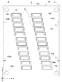
図2は、ステージ5側から視察したサブキャリッジ50と複数の液滴吐出ヘッド51とを示す平面図である。同図の紙面に垂直な方向がZ軸方向である。また、紙面の左右方向がX軸方向であり、紙面の上下方向がY軸方向である。サブキャリッジ50のサブキャリッジプレート54は、それぞれほぼ同じ構造を有する複数の液滴吐出ヘッド51を保持している。本実施例では、サブキャリッジ50に保持される液滴吐出ヘッド51の数は24個である。それぞれの液滴吐出ヘッド51は、複数のノズル52が設けられた底面を有している。それぞれの液滴吐出ヘッド51のこの底面の形状は、2つの長辺と2つの短辺とを有する四角形である。サブキャリッジ50に保持された液滴吐出ヘッド51の底面はステージ5側を向いており、さらに、液滴吐出ヘッド51の長辺方向と短辺方向とは、それぞれX軸方向とY軸方向とにほぼ平行である。
FIG. 2 is a plan view showing the sub-carriage 50 and the plurality of droplet discharge heads 51 as viewed from the
また、複数の液滴吐出ヘッド51のノズル52のそれぞれの相対位置は、サブキャリッジ組立装置等の装置により精度良く位置調整されている。サブキャリッジ50には、2個の案内孔101,102がA面に沿って配設されている。また、X軸方向の対辺A面およびB面には、雌ねじ104a,104b,104c,104dが配設されている。このサブキャリッジ50は、矢印103の方向に移載されてキャリッジ3に固定されているキャリッジ取付部30に挿着される。液滴吐出ヘッド51のノズル52が構成しているノズル列(図示せず)を結んだ仮想線が、X軸方向を向いていれば、液滴吐出装置1(図1参照)に対して挿入される方向は、X方向またはY方向のどちらの方向でもよい。サブキャリッジプレート54のX軸方向の対辺をA面およびB面と表記する。
The relative positions of the
また、複数の液滴吐出ヘッド51のそれぞれには、液状材料11を吐出するための液滴吐出装置1との電気的接続および液状材料用の配管としてのチューブ13と接続する必要がある。本実施例では、後述するようにこれらの接続を一度に行うようにしている。
Each of the plurality of droplet discharge heads 51 needs to be electrically connected to the droplet discharge device 1 for discharging the
また、サブキャリッジプレート54の四隅に配設されている4個の孔109は、後述する反転作業台500の仮置き台501に止めねじ502によって固定されるための孔である。
Further, the four
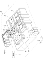
図3は、サブキャリッジ50とキャリッジ取付部30と関係を示す斜視図である。キャリッジ取付部30は、液滴吐出装置1のキャリッジ3に案内孔31a,31bとでキャリッジ3(図1参照)に配設されている2本のピン(図示せず)で位置決めされ、4本の雌ねじ32a,32b,32c,32dを使用して固定されている。
FIG. 3 is a perspective view showing the relationship between the sub-carriage 50 and the
キャリッジ取付部30の底面の近傍のY軸方向に沿う両側には、ガイドとしての2本のガイドレール(1本は図示せず)33が配設されている。また、ガイドレール33に対して略垂直方向の面にねじ止め用の4個の孔34a,34b,34c,34d(34cおよび34dは図示せず)が配設されている。ガイドレール33のサブキャリッジ50が挿入される一端には、度当たりピン35a,35b(35bは図示せず)が2本のガイドレールのそれぞれに配設されている。
Two guide rails (one not shown) 33 as guides are arranged on both sides along the Y-axis direction near the bottom surface of the
また、キャリッジ取付部30のサブキャリッジ50が挿入される反対の面には、コネクタボード固定側36が、キャリッジ取付部30に固定されている。このコネクタボード固定側36には、複数の電気コネクタ37aと複数の液状材料用コネクタ38aが、Y軸方向に平行な面で接続するように配設されている。また、平行孔部を有する案内孔部材58a,58b(58bは図示せず)が配設されている。
A connector
この複数の電気コネクタ37aは、液滴吐出装置1の制御回路(図示せず)と電気的に接続され、液滴吐出ヘッド51からの液状材料11の吐出が制御される。また、複数の液状材料用コネクタ38aは配管およびチューブ13を介してタンク12に接続され、このタンク12の中に貯留されている液状材料11が液滴吐出ヘッド51に供給される。
The plurality of
サブキャリッジ50の外形としてのサブキャリッジプレート54のA面およびB面には、キャリッジ取付部30の孔34a,34b,34c,34dに対応した雌ねじ104a,104b,104c,104d(104c,104dは図示せず)が配設されている。また、サブキャリッジプレート54の上面には、度当たり55がA面およびB面に対応して配設され、キャリッジ取付部30に配設されている度当たりピン35a,35bに当接する位置となっている。
On the A and B surfaces of the
サブキャリッジ50の上部には、液滴吐出ヘッド用回路部56が配設され、サブキャリッジプレート54に配設されている複数の液滴吐出ヘッド51を駆動制御している。また、サブキャリッジ50のキャリッジ取付部30に挿入されるZ軸−X軸を含む面にコネクタボード39が配設されている。
A
コネクタボード39には、キャリッジ取付部30に配設されている複数の電気コネクタ37aおよび複数の液状材料用コネクタ38aとそれぞれ対応する、複数の電気コネクタ37bおよび複数の液状材料用コネクタ38bが配設されている。複数の電気コネクタ37bは、液滴吐出ヘッド用回路部56と電気的に接続している。また、複数の液状材料用コネクタ38bは、複数の液滴吐出ヘッド51とチューブ等の配管部材を介して配管されている。
The
また、コネクタボード39には、一対の案内ピン57a,57b(57bは図示せず)が配設され、キャリッジ取付部30のコネクタボード固定側36に配設されている平行孔部を有する案内孔部材58a,58bと係合するようになっている。この関係については、後述する。
The
このように構成されている、キャリッジ取付部30にサブキャリッジ50を挿入する。先ず、サブキャリッジプレート54のA面およびB面の先端部が、キャリッジ取付部30に配設されている2本のガイドレール33に接触して係合する。なおも、サブキャリッジプレート54を付勢して押し込むと、サブキャリッジプレート54に配設されている度当たり55が、2本のガイドレール33の少なくとも一本に配設されている度当たりピン35a,35bに当接して止まる。この時点で、サブキャリッジ50とキャリッジ取付部30との相対位置はZ軸方向だけ決定されている。
The sub-carriage 50 is inserted into the
次に、X軸およびY軸方向の相対位置を決定する方法について説明する。サブキャリッジプレート54に配設されている案内孔101,102と対応する案内孔105,106が2本のガイドレール33にも配設されている。2本の段付きの位置決めピン107,108を上方から差し込む。これにより、サブキャリッジ50とキャリッジ取付部30との相対位置が決定される。
Next, a method for determining the relative positions in the X-axis and Y-axis directions will be described. Guide holes 105 and 106 corresponding to the guide holes 101 and 102 provided in the
次に、サブキャリッジ50とキャリッジ取付部30とが、液滴吐出装置1で液状材料11を吐出する際に、振動等の発生が予測されるため、ガイドレール33に配設されているねじ止め用の4個の孔34a,34b,34c,34d(34cおよび34dは図示せず)と、サブキャリッジプレート54のA面およびB面に配設されている雌ねじ104a,104b,104c,104dとでねじ止めして固定される。
Next, when the sub-carriage 50 and the
次に、サブキャリッジ50がキャリッジ取付部30に挿入される場合のコネクタボード固定側36とコネクタボード39との関係について詳述する。
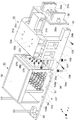
図4は、サブキャリッジ50とキャリッジ取付部30とを取り付ける過程を示す断面図である。キャリッジ取付部30に固定されているコネクタボード固定側36には、複数の電気コネクタ37a(図示は1個)と複数の液状材料用コネクタ38a(図示は1個)と一対の案内孔部材58a,58bとが配設されている。複数の電気コネクタ37aは、液滴吐出装置1の液滴吐出ヘッド51の制御部7(図1参照)に電気的に接続されている。また、複数の液状材料用コネクタ38aは、チューブ13を介してタンク12に接続され液状材料11が液滴吐出ヘッド51に供給される。また、一対の案内孔部材58a,58bには、サブキャリッジ50側に開口した斜面部59と平行孔部60とを有している。
Next, the relationship between the connector
FIG. 4 is a cross-sectional view showing a process of attaching the sub-carriage 50 and the
サブキャリッジ50に固定されているコネクタボード39には、一対の案内ピン57a,57bが配設されている。案内ピン57a,57bは、案内ピンガイド61,62によって案内されている。案内ピン57a,57bは、案内ピンガイド61,62の中を長手方向に摺動する。案内ピン57a,57bと案内ピンガイド61,62との間には、弾性体としての例えばコイルバネ63,64が配設され、案内ピン57a,57bはコネクタボード固定側36の方向に付勢されている。また、案内ピン57a,57bが案内ピンガイド61,62から飛び出さないように、Eリング65,66が長手方向を規制している。
A pair of guide pins 57 a and 57 b are disposed on the
また、サブキャリッジ50に固定されているコネクタボード39には、複数の電気コネクタ37b(図示は1個)と複数の液状材料用コネクタ38b(図示は1個)とが配設されている。
The
次に、サブキャリッジ50とキャリッジ取付部30とが取り付けられる順序を説明する。
サブキャリッジ50は、キャリッジ取付部30に配設されているガイドレール33によってX軸、Y軸、Z軸のそれぞれの方向に規制されているが、複数の電気コネクタ37aと複数の電気コネクタ37b、および複数の液状材料用コネクタ38aと複数の液状材料用コネクタ38bとの接続を確実にするほどに精度良く案内されてはいない。
Next, the order in which the sub-carriage 50 and the
The sub-carriage 50 is regulated in the X-axis, Y-axis, and Z-axis directions by
そこで、コネクタボード39に配設されている案内ピン57a,57bの先端部が、コネクタボード固定側36に配設されている案内孔部材58a,58bが有する平行孔部60の入口に達した時点で、複数の電気コネクタ37aと複数の電気コネクタ37b、および複数の液状材料用コネクタ38aと複数の液状材料用コネクタ38bは接していない位置関係にされている。
Therefore, when the leading ends of the guide pins 57a and 57b disposed on the
このことは、先ず案内ピン57a,57bと案内孔部材58a,58bが有する平行孔部60とで、キャリッジ取付部30に対するサブキャリッジ50の位置が修正されて、相対位置が決まる。この後、さらにサブキャリッジ50がキャリッジ取付部30に近づくと、案内ピン57a,57bは案内孔部材58a,58bが有する平行孔部60の中に充分挿入される。その後に、複数の電気コネクタ37aと複数の電気コネクタ37bとが電気的に接続されるとともに、複数の液状材料用コネクタ38aと複数の液状材料用コネクタ38bとが接続される。
This is because the position of the sub-carriage 50 with respect to the
この接続により、電気的には液滴吐出装置1の液滴吐出ヘッド51を駆動制御している制御部7(図1参照)と接続される。また、各液滴吐出ヘッド51は、タンク12とチューブ13を介して接続される。
This connection is electrically connected to the control unit 7 (see FIG. 1) that drives and controls the
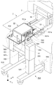
図5は、サブキャリッジ50を取り付けた反転作業台500の斜視図である。4個のローラを四隅に配設された脚510より上方に立設する2本の支柱520が配設されている。それぞれの支柱520の先端部には、仮置き台501が配設されている。仮置き台501は、一対の軸503により支えられ、この軸503を中心に回動することができる。この一対の軸503には、回転止めレバー504がそれぞれに配設されている。
FIG. 5 is a perspective view of the inversion work table 500 to which the sub-carriage 50 is attached. Two struts 520 are provided for standing four rollers above the
この仮置き台501の上にサブキャリッジ50が4本の止めねじ502(1本は図示せず)によって固定されて、サブキャリッジ50の電気的な補修および点検を行うとともに液滴吐出ヘッド51周りの点検を行う。液滴吐出ヘッド51を点検する場合は、回転止めレバー504を反時計回り方向に回転し、円板530に配設されている多数の小さい穴と回転止めレバー504に配設されているロックピン(図示せず)とによって、仮置き台501とともにサブキャリッジ50が回転され所望の角度に位置決めされる。下方にあった液滴吐出ヘッド51が上方に位置するようになる。
The sub-carriage 50 is fixed on the temporary placement table 501 by four set screws 502 (one is not shown), and the sub-carriage 50 is electrically repaired and inspected, and the
また、2本の支柱520の中央部には、付勢部材としてのエアシリンダ(図示せず)またはコイルバネ(図示せず)が内蔵され仮置き台501を上下に可動することができるようになっている。サブキャリッジ50の補修および点検をする場合は、仮置き台501を上下して、作業者の体型に合った位置で作業することができる。
In addition, an air cylinder (not shown) or a coil spring (not shown) as a biasing member is built in the central portion of the two
サブキャリッジ50の補修および点検が終了すると、サブキャリッジ50を液滴吐出装置1のキャリッジ取付部30に挿着する。先ず、サブキャリッジ50が固定されている反転作業台500を液滴吐出装置1の近傍に移動する。4本の止めねじ502を外し、脚510には二箇所に突起部540が配設されていて、液滴吐出装置1の脚部には、凹部550が二箇所に突起部540に対応して配設されている。反転作業台500の二箇所の突起部540を液滴吐出装置1の二箇所の凹部550に係合させて、反転作業台500と液滴吐出装置1との相対位置を決める。
When the repair and inspection of the sub-carriage 50 are completed, the sub-carriage 50 is inserted into the
次に、支柱520に内蔵されているエアシリンダ等を作動させ、サブキャリッジ50が固定されている仮置き台501を下方から上方に向けて移動する。仮置き台501の先端部501bは、サブキャリッジ50より前方に突出してキャリッジ3に固定されているキャリッジ取付部30のガイドレール33に当接し、上下方向の位置決めをする。しかも、仮置き台501の先端部501aの両側は略垂直に屈曲して一対を成し、ガイドレール33に対して水平方向の位置決めもすることができるようになっている。
Next, an air cylinder or the like built in the
次に、サブキャリッジ50を固定している4本の止めねじ502を外す。サブキャリッジ50に配設されている2本のハンドル560を握って前方(キャリッジ取付部30の方向)にスライドさせる。前述したように、キャリッジ取付部30のガイドレール33は略水平に配設され、サブキャリッジ50を装着する場合にはガイドレール33には案内ピンのような障害物がないため、サブキャリッジ50は略水平に載せ込むことができる。
Next, the four set
以下、本実施例の効果を記載する。
(1)サブキャリッジ50の外形とキャリッジ取付部30に配設されたガイドとによって、大型なユニットであるサブキャリッジ50の液滴吐出装置1への脱着する際に、作業者が上に持上げる動作をなくして楽に効率良く取付けすることができる。
The effects of this example will be described below.
(1) The operator lifts the sub-carriage 50 up and down when the sub-carriage 50, which is a large unit, is attached to and detached from the droplet discharge device 1 by the outer shape of the sub-carriage 50 and the guides disposed on the
(2)サブキャリッジ50とキャリッジ取付部30に配設されている複数の電気的コネクタ37a,37bおよび複数の液状材料用コネクタ38a,38bでの接続が、サブキャリッジ50をキャリッジ取付部30に押し込むだけで接続され、接続ミスも皆無となり効率良く取付けすることができる。
(2) The connection between the sub-carriage 50 and the plurality of
(3)反転作業台500により、サブキャリッジ50の撓みを防止することができるため、高精度に位置決めされた複数の液滴吐出ヘッド51の位置ずれを防止することができる。
(3) Since the
(4)反転作業台500に固定されたサブキャリッジ50を回動することができるため、作業者が所望するサブキャリッジ50の角度を調節して作業することができる。
(4) Since the
(5)反転作業台500の支柱520に内蔵されているエアシリンダ等の付勢部材により、サブキャリッジ50の上下移動がされるため、安全な作業をすることができる。
(5) Since the sub-carriage 50 is moved up and down by an urging member such as an air cylinder built in the
1…液滴吐出装置、2…吐出走査部、3…キャリッジ、4…第2位置制御装置、5…ステージ、6…第1位置制御装置、7…制御部、8…メンテナンス装置、10A…基体、11…液状材料、12…タンク、13…チューブ、21…被吐出部、30…キャリッジ取付部、31a,31b…案内孔、32a,32b,32c,32d…雌ねじ、33…ガイドレール、34a,34b,34c,34d…孔、35a,35b…度当たりピン、36…コネクタボード固定側、37a…電気コネクタ、37a,37b…電気的コネクタ、37b…電気コネクタ、38a…液状材料用コネクタ、38a,38b…液状材料用コネクタ、38b…液状材料用コネクタ、39…コネクタボード、50…サブキャリッジ、51…液滴吐出ヘッド、52…ノズル、53…ヘッドユニット、54…サブキャリッジプレート、55…度当たり、56…液滴吐出ヘッド用回路部、57a,57b…案内ピン、58a,58b…案内孔部材、59…斜面部、60…平行孔部、61,62…案内ピンガイド、63,64…コイルバネ、65,66…Eリング、101,102…案内孔、103…矢印、104a,104b,104c,104d…雌ねじ、105,106…案内孔、107,108…位置決めピン、500…反転作業台、501…仮置き台、501a,501b…先端部、502…止めねじ、503…軸、504…回転止めレバー、510…脚、520…支柱、円板…530、540…突起部、550…凹部、560…ハンドル。
DESCRIPTION OF SYMBOLS 1 ... Droplet discharge apparatus, 2 ... Discharge scanning part, 3 ... Carriage, 4 ... 2nd position control apparatus, 5 ... Stage, 6 ... 1st position control apparatus, 7 ... Control part, 8 ... Maintenance apparatus, 10A ... Base |
Claims (12)
前記複数の液滴吐出ヘッドが配設されたサブキャリッジと、
前記サブキャリッジが脱着されるキャリッジ取付部と、
前記サブキャリッジの外形と前記キャリッジ取付部に配設されたガイドとによって取り付けることを特徴とするヘッドユニット。 A plurality of droplet discharge heads;
A sub-carriage provided with the plurality of droplet discharge heads;
A carriage mounting portion from which the sub-carriage is attached and detached
The head unit is attached by an outer shape of the sub-carriage and a guide disposed on the carriage attachment portion.
The head unit mounting method according to claim 10 or 11, wherein a height of the temporary table is adjusted by a vertically movable portion disposed below the temporary table, and a part of the temporary table. Alternatively, the head is characterized in that a part of the sub-carriage abuts a part of the carriage of the droplet discharge device or a part of the carriage mounting part to determine a relative position between the temporary placement table and the carriage mounting part. How to install the unit.
Priority Applications (1)
| Application Number | Priority Date | Filing Date | Title |
|---|---|---|---|
| JP2004057585A JP4622269B2 (en) | 2004-03-02 | 2004-03-02 | Head unit |
Applications Claiming Priority (1)
| Application Number | Priority Date | Filing Date | Title |
|---|---|---|---|
| JP2004057585A JP4622269B2 (en) | 2004-03-02 | 2004-03-02 | Head unit |
Publications (2)
| Publication Number | Publication Date |
|---|---|
| JP2005246169A true JP2005246169A (en) | 2005-09-15 |
| JP4622269B2 JP4622269B2 (en) | 2011-02-02 |
Family
ID=35027171
Family Applications (1)
| Application Number | Title | Priority Date | Filing Date |
|---|---|---|---|
| JP2004057585A Expired - Lifetime JP4622269B2 (en) | 2004-03-02 | 2004-03-02 | Head unit |
Country Status (1)
| Country | Link |
|---|---|
| JP (1) | JP4622269B2 (en) |
Cited By (4)
| Publication number | Priority date | Publication date | Assignee | Title |
|---|---|---|---|---|
| JP2007216605A (en) * | 2006-02-20 | 2007-08-30 | Toppan Printing Co Ltd | Ink discharge unit attaching / detaching device, ink discharging device, and ink discharging unit attaching / detaching method |
| JP2011093174A (en) * | 2009-10-29 | 2011-05-12 | Seiko Epson Corp | Carriage device and inkjet apparatus |
| JP2013252723A (en) * | 2013-09-27 | 2013-12-19 | Seiko Epson Corp | Carriage device and printing device |
| JP2019098540A (en) * | 2017-11-29 | 2019-06-24 | 理想科学工業株式会社 | Ink jet head module |
Citations (5)
| Publication number | Priority date | Publication date | Assignee | Title |
|---|---|---|---|---|
| JPH04141444A (en) * | 1990-10-03 | 1992-05-14 | Canon Inc | Ink jet recording apparatus |
| JPH0523931A (en) * | 1991-05-13 | 1993-02-02 | Daifuku Co Ltd | Parts feeding equipment |
| JP2001201528A (en) * | 2000-01-18 | 2001-07-27 | Hiroshi Fujimoto | Conduction testing device of wiring board or the like |
| JP2003094621A (en) * | 2001-09-26 | 2003-04-03 | Sony Corp | Inkjet printer |
| JP2003127343A (en) * | 2001-10-19 | 2003-05-08 | Seiko Epson Corp | Head unit, method of setting the same, electronic equipment, method of manufacturing liquid crystal display device, method of manufacturing organic EL device, method of manufacturing electron emission device, method of manufacturing PDP device, method of manufacturing electrophoretic display device, manufacture of color filter Method, organic EL manufacturing method, spacer forming method, metal wiring forming method, lens forming method, resist forming method, and light diffuser forming method |
-
2004
- 2004-03-02 JP JP2004057585A patent/JP4622269B2/en not_active Expired - Lifetime
Patent Citations (5)
| Publication number | Priority date | Publication date | Assignee | Title |
|---|---|---|---|---|
| JPH04141444A (en) * | 1990-10-03 | 1992-05-14 | Canon Inc | Ink jet recording apparatus |
| JPH0523931A (en) * | 1991-05-13 | 1993-02-02 | Daifuku Co Ltd | Parts feeding equipment |
| JP2001201528A (en) * | 2000-01-18 | 2001-07-27 | Hiroshi Fujimoto | Conduction testing device of wiring board or the like |
| JP2003094621A (en) * | 2001-09-26 | 2003-04-03 | Sony Corp | Inkjet printer |
| JP2003127343A (en) * | 2001-10-19 | 2003-05-08 | Seiko Epson Corp | Head unit, method of setting the same, electronic equipment, method of manufacturing liquid crystal display device, method of manufacturing organic EL device, method of manufacturing electron emission device, method of manufacturing PDP device, method of manufacturing electrophoretic display device, manufacture of color filter Method, organic EL manufacturing method, spacer forming method, metal wiring forming method, lens forming method, resist forming method, and light diffuser forming method |
Cited By (5)
| Publication number | Priority date | Publication date | Assignee | Title |
|---|---|---|---|---|
| JP2007216605A (en) * | 2006-02-20 | 2007-08-30 | Toppan Printing Co Ltd | Ink discharge unit attaching / detaching device, ink discharging device, and ink discharging unit attaching / detaching method |
| JP2011093174A (en) * | 2009-10-29 | 2011-05-12 | Seiko Epson Corp | Carriage device and inkjet apparatus |
| JP2013252723A (en) * | 2013-09-27 | 2013-12-19 | Seiko Epson Corp | Carriage device and printing device |
| JP2019098540A (en) * | 2017-11-29 | 2019-06-24 | 理想科学工業株式会社 | Ink jet head module |
| JP7096660B2 (en) | 2017-11-29 | 2022-07-06 | 理想科学工業株式会社 | Printing equipment and inkjet head module |
Also Published As
| Publication number | Publication date |
|---|---|
| JP4622269B2 (en) | 2011-02-02 |
Similar Documents
| Publication | Publication Date | Title |
|---|---|---|
| KR100691719B1 (en) | Droplet ejection apparatus, electro-optical device, manufacturing method of electro-optical device and electronic equipment | |
| JP2009147240A (en) | Substrate support apparatus, substrate support method, substrate processing apparatus, substrate processing method, and manufacturing method of display device constituent member | |
| WO2007123077A1 (en) | Drop coating apparatus | |
| WO2007129634A1 (en) | Droplet applying apparatus | |
| US8141977B2 (en) | Inkjet head module and method of aligning inkjet head using the same | |
| US20070222809A1 (en) | Droplet jet inspecting device, droplet jetting applicator and method for manufacturing coated body | |
| JP2011062681A (en) | Multi inkjet head package, inkjet recording device using the same, and method for aligning multi inkjet head package at inkjet recording device | |
| JP5560092B2 (en) | Housing for inkjet head | |
| JP4622269B2 (en) | Head unit | |
| US7384140B2 (en) | Liquid droplet ejecting apparatus, liquid droplet ejecting system, electro-optical device, method of manufacturing electro-optical device, method of forming a metal wiring line, and electronic apparatus | |
| CN102189057A (en) | Liquid droplet discharging apparatus | |
| KR20220005992A (en) | Droplet ejection apparatus and position adjusting method | |
| JP2005224685A (en) | Sub-carriage with multiple IJ heads and assembly method thereof | |
| KR102855180B1 (en) | Substrate treating apparatus | |
| JP2004172321A (en) | Work transfer table, work transfer device, droplet discharge device, electro-optical device, method of manufacturing electro-optical device, and electronic apparatus | |
| JP4207541B2 (en) | Work transfer table, work transfer device, droplet discharge device, electro-optical device, electro-optical device manufacturing method, and electronic apparatus | |
| JP2012086194A (en) | Drawing device and drawing method | |
| JP2004243187A (en) | Droplet discharge device, electro-optical device, method of manufacturing electro-optical device, and electronic apparatus | |
| JP4449317B2 (en) | Droplet ejection apparatus and electro-optic device manufacturing method | |
| KR20230092054A (en) | Inkjet head alignment apparatus and inkjet printing apparatus including the same | |
| JP2004243186A (en) | Elongated body arrangement structure, droplet discharge device, electro-optical device, method of manufacturing electro-optical device, and electronic apparatus | |
| JP2004172317A (en) | Work positioning device, work positioning method, droplet discharge device, electro-optical device, method of manufacturing electro-optical device, and electronic apparatus | |
| JP2006248654A (en) | Work transfer device, work processing system, electro-optical device manufacturing method, electro-optical device, circuit board manufacturing method, circuit board, and electronic apparatus | |
| CN114649236B (en) | Maintenance unit and substrate processing apparatus having the same | |
| JP2006248655A (en) | Work transfer method, work transfer system, electro-optical device manufacturing method, electro-optical device, circuit board manufacturing method, circuit board, and electronic apparatus |
Legal Events
| Date | Code | Title | Description |
|---|---|---|---|
| A621 | Written request for application examination |
Free format text: JAPANESE INTERMEDIATE CODE: A621 Effective date: 20061225 |
|
| RD04 | Notification of resignation of power of attorney |
Free format text: JAPANESE INTERMEDIATE CODE: A7424 Effective date: 20070403 |
|
| A977 | Report on retrieval |
Free format text: JAPANESE INTERMEDIATE CODE: A971007 Effective date: 20090716 |
|
| A131 | Notification of reasons for refusal |
Free format text: JAPANESE INTERMEDIATE CODE: A131 Effective date: 20090825 |
|
| A521 | Request for written amendment filed |
Free format text: JAPANESE INTERMEDIATE CODE: A523 Effective date: 20091022 |
|
| A131 | Notification of reasons for refusal |
Free format text: JAPANESE INTERMEDIATE CODE: A131 Effective date: 20100511 |
|
| A521 | Request for written amendment filed |
Free format text: JAPANESE INTERMEDIATE CODE: A523 Effective date: 20100707 |
|
| TRDD | Decision of grant or rejection written | ||
| A01 | Written decision to grant a patent or to grant a registration (utility model) |
Free format text: JAPANESE INTERMEDIATE CODE: A01 Effective date: 20101005 |
|
| A01 | Written decision to grant a patent or to grant a registration (utility model) |
Free format text: JAPANESE INTERMEDIATE CODE: A01 |
|
| A61 | First payment of annual fees (during grant procedure) |
Free format text: JAPANESE INTERMEDIATE CODE: A61 Effective date: 20101018 |
|
| R150 | Certificate of patent or registration of utility model |
Ref document number: 4622269 Country of ref document: JP Free format text: JAPANESE INTERMEDIATE CODE: R150 |
|
| FPAY | Renewal fee payment (event date is renewal date of database) |
Free format text: PAYMENT UNTIL: 20131112 Year of fee payment: 3 |
|
| S531 | Written request for registration of change of domicile |
Free format text: JAPANESE INTERMEDIATE CODE: R313532 |
|
| R350 | Written notification of registration of transfer |
Free format text: JAPANESE INTERMEDIATE CODE: R350 |
|
| S111 | Request for change of ownership or part of ownership |
Free format text: JAPANESE INTERMEDIATE CODE: R313113 |
|
| R360 | Written notification for declining of transfer of rights |
Free format text: JAPANESE INTERMEDIATE CODE: R360 |
|
| R360 | Written notification for declining of transfer of rights |
Free format text: JAPANESE INTERMEDIATE CODE: R360 |
|
| R371 | Transfer withdrawn |
Free format text: JAPANESE INTERMEDIATE CODE: R371 |
|
| S111 | Request for change of ownership or part of ownership |
Free format text: JAPANESE INTERMEDIATE CODE: R313113 |
|
| R350 | Written notification of registration of transfer |
Free format text: JAPANESE INTERMEDIATE CODE: R350 |
|
| R250 | Receipt of annual fees |
Free format text: JAPANESE INTERMEDIATE CODE: R250 |
|
| R250 | Receipt of annual fees |
Free format text: JAPANESE INTERMEDIATE CODE: R250 |
|
| R250 | Receipt of annual fees |
Free format text: JAPANESE INTERMEDIATE CODE: R250 |
|
| R250 | Receipt of annual fees |
Free format text: JAPANESE INTERMEDIATE CODE: R250 |
|
| R250 | Receipt of annual fees |
Free format text: JAPANESE INTERMEDIATE CODE: R250 |
|
| R250 | Receipt of annual fees |
Free format text: JAPANESE INTERMEDIATE CODE: R250 |
|
| EXPY | Cancellation because of completion of term |