JP2005247227A - Hydraulic control device - Google Patents
Hydraulic control device Download PDFInfo
- Publication number
- JP2005247227A JP2005247227A JP2004063288A JP2004063288A JP2005247227A JP 2005247227 A JP2005247227 A JP 2005247227A JP 2004063288 A JP2004063288 A JP 2004063288A JP 2004063288 A JP2004063288 A JP 2004063288A JP 2005247227 A JP2005247227 A JP 2005247227A
- Authority
- JP
- Japan
- Prior art keywords
- pump
- motor
- control unit
- oil passage
- rotor
- Prior art date
- Legal status (The legal status is an assumption and is not a legal conclusion. Google has not performed a legal analysis and makes no representation as to the accuracy of the status listed.)
- Pending
Links
Images

Classifications
-
- B—PERFORMING OPERATIONS; TRANSPORTING
- B60—VEHICLES IN GENERAL
- B60T—VEHICLE BRAKE CONTROL SYSTEMS OR PARTS THEREOF; BRAKE CONTROL SYSTEMS OR PARTS THEREOF, IN GENERAL; ARRANGEMENT OF BRAKING ELEMENTS ON VEHICLES IN GENERAL; PORTABLE DEVICES FOR PREVENTING UNWANTED MOVEMENT OF VEHICLES; VEHICLE MODIFICATIONS TO FACILITATE COOLING OF BRAKES
- B60T8/00—Arrangements for adjusting wheel-braking force to meet varying vehicular or ground-surface conditions, e.g. limiting or varying distribution of braking force
- B60T8/32—Arrangements for adjusting wheel-braking force to meet varying vehicular or ground-surface conditions, e.g. limiting or varying distribution of braking force responsive to a speed condition, e.g. acceleration or deceleration
- B60T8/34—Arrangements for adjusting wheel-braking force to meet varying vehicular or ground-surface conditions, e.g. limiting or varying distribution of braking force responsive to a speed condition, e.g. acceleration or deceleration having a fluid pressure regulator responsive to a speed condition
- B60T8/36—Arrangements for adjusting wheel-braking force to meet varying vehicular or ground-surface conditions, e.g. limiting or varying distribution of braking force responsive to a speed condition, e.g. acceleration or deceleration having a fluid pressure regulator responsive to a speed condition including a pilot valve responding to an electromagnetic force
- B60T8/3615—Electromagnetic valves specially adapted for anti-lock brake and traction control systems
- B60T8/3675—Electromagnetic valves specially adapted for anti-lock brake and traction control systems integrated in modulator units
- B60T8/368—Electromagnetic valves specially adapted for anti-lock brake and traction control systems integrated in modulator units combined with other mechanical components, e.g. pump units, master cylinders
Landscapes
- Physics & Mathematics (AREA)
- Electromagnetism (AREA)
- Engineering & Computer Science (AREA)
- Fluid Mechanics (AREA)
- Transportation (AREA)
- Mechanical Engineering (AREA)
- Regulating Braking Force (AREA)
Abstract
Description
本発明は、液圧制御装置において、特にブラシレスモータを用いた液圧制御ユニットから構成される液圧制御装置に関するものである。 The present invention relates to a hydraulic pressure control device, and more particularly to a hydraulic pressure control device including a hydraulic pressure control unit using a brushless motor.
液圧制御装置として、特許文献1に記載の技術が開示されている。この公報に記載の技術には、ブラシレスモータを用いたブレーキ液圧制御ユニットにおいて、ロータに近接して配置された回転センサによりブラシレスモータのロータ位置を検出する構成としている。
しかしながら、上述のブレーキ液圧制御装置にあっては、下記に示す問題があった。すなわち、ロータ位置を検出する回転センサがロータに近接して配置される構成としているため、ロータの磁気的な外乱が位置センサの検出精度に影響を与え、検出精度が低下する虞がある。尚、磁気的影響を防止するためにシールドすることも考えられるが、コストアップに繋がるという問題がある。 However, the above-described brake fluid pressure control device has the following problems. That is, since the rotation sensor for detecting the rotor position is arranged close to the rotor, the magnetic disturbance of the rotor may affect the detection accuracy of the position sensor, and the detection accuracy may be reduced. Although shielding to prevent magnetic influences can be considered, there is a problem that the cost is increased.
本発明は、上記問題に着目してなされたもので、液圧制御装置において、位置センサに対するロータの磁気的影響を抑制することを目的とする。 The present invention has been made paying attention to the above problem, and an object of the present invention is to suppress the magnetic influence of the rotor on the position sensor in the hydraulic pressure control device.
上記目的を達成するため、液圧制御装置において、内部にポンプが配置されたハウジングと、該ハウジングの第1の側面に固定され、回転軸により前記ポンプを駆動するモータと、前記ポンプを挟んで対向する位置であって、モータの回転軸に固定された被検出部材と、前記被検出部材に対向する位置であって、前記ハウジング側に固定され、前記被検出部材の位置を検出する検出部材とからなる位置センサを備えることとした。 In order to achieve the above object, in a hydraulic control device, a housing in which a pump is disposed, a motor fixed to a first side surface of the housing and driving the pump by a rotating shaft, and the pump interposed therebetween A detection member fixed to the rotation shaft of the motor, and a detection member fixed to the housing side and detecting the position of the detection member. A position sensor consisting of
よって、位置センサとロータの位置を離して配置することが可能となり、位置センサに対するロータの磁気的影響を抑制することができる。 Therefore, it becomes possible to arrange | position the position sensor and the position of a rotor apart, and the magnetic influence of the rotor with respect to a position sensor can be suppressed.
以下、本発明の液圧制御装置を実現する最良の形態を、図面に示す実施例1に基づいて説明する。 Hereinafter, the best mode for realizing the hydraulic pressure control device of the present invention will be described based on Example 1 shown in the drawings.
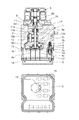
図1は実施例1におけるブレーキ液圧制御ユニットを表す図である。図1中ブロック1の上面にはポンプ駆動用のモータ6を取り付けるモータ取付面14が設けられている。このモータ取付面14と対向するブロック1の下面には、電磁弁3及び電磁弁3を覆うケース17を取り付けるケース取付面15が設けられている。モータ6はブラシレスモータとされており、モータ駆動軸6bを軸支すると共に、ブロック1とボルト6cによって固定可能なモータフランジ部6aが設けられている。
FIG. 1 is a diagram illustrating a brake fluid pressure control unit according to the first embodiment. A
モータ取付面14には、ブロック1に対しモータフランジ部6aと嵌合するとともに、モータ駆動軸6bとポンプ駆動軸10aを連結する連結部8を収装するモータ取付孔11が設けられている。モータ取付孔11の底面部には、小径のシール孔11a及び更に小径の軸受け孔11bが設けられている。シール孔11aにはポンプ駆動軸10aを回転摺動可能にシールするオイルシール9aが設けられ、軸受け孔11bにはポンプ駆動軸10aを回転可能に支持する軸受けが設けられている。
The
ケース取付面15には、ポンプ2を収装するためのシリンダ孔12と、シリンダ孔12の蓋体であって、位置センサ4を収装するサブブロック7が設けられている。また、ブレーキ制御を達成する複数の電磁弁3が圧入固定されている。
The
サブブロック7の下面には、位置センサ4を収装する収装孔7aと、収装孔7aの底面部に設けられた小径のシール孔7b及び更に小径の軸受け孔7cが設けられている。シール孔7bにはポンプ駆動軸10aを摺動可能にシールするオイルシール9bが設けられ、軸受け孔7cにはモータ駆動軸10aを回転可能に支持する軸受けが設けられている。サブブロック7の収装孔7aには、ポンプ駆動軸10aの端部に固定され、ポンプ駆動軸10aと一体に回転するロータ位置被検出部材4bが配置されている。このロータ位置被検出部材4bと対向する位置であって、位置センサ4のロータ位置検出部材4aが固定された蓋体7dによって下面側から覆われている。
On the lower surface of the
尚、本実施例1の位置センサ4は、複数の磁石が配置されたロータ位置被検出部材4bと、この複数の磁石の磁束変化を検出するロータ位置検出部材4aから構成された磁気センサであり、回転位置に応じた磁束変化に基づいてモータ駆動軸6bの位置を検出する。ただし、電気的及び磁気的変化等に応じて位置を検出するものであればよく、特に限定しない。
The
更に、ケース取付面15には、サブブロック7及び電磁弁3を覆うケース部材17が設けられている。また、ケース部材17の下面には、コントロールユニット5を覆うカバー18が設けられている。ロータ位置検出部材4aは出力ライン4cを介して電気的接続部19にてコントロールユニット5と接続されている。また、電磁弁3は電気的接続部16にてコントロールユニット5と接続されている。
Further, a
すなわち、図1のブレーキ液圧制御ユニットにあっては、モータ6のモータ駆動軸6bの回転位置を検出する位置センサ4を、モータ6に対しギヤポンプ2を挟んで対向する側に配置した構成としている。これにより、位置センサ4をモータ6と離れた位置に配置することが可能となり、位置センサ4はモータ6の磁気的影響を受けにくくなるため、ロータ位置の検出精度の低下を抑制することができる。
That is, in the brake fluid pressure control unit of FIG. 1, the
また、シールドを新たに設ける必要が無く、ロータがロータ位置検出部材4aに及ぼす磁気的影響を抑制できるため、コスト増大を抑制することができる。
Further, it is not necessary to newly provide a shield, and the magnetic influence of the rotor on the rotor
また、ブロック1のモータ取付面14にモータ6を取り付け、対向するケース取付面15側からポンプ2を組み付けている。よって、ブロック1を衝として位置決めをすることが可能となり、位置決めピン等を別途設けることなく精度の高いユニットを構成することができる。
Further, the
[前輪側油圧ユニットについて]
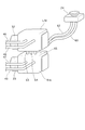
図2は、実施例1における前輪側油圧ユニットを表す図である。前輪側油圧ユニットは左輪側油圧ユニットL/U及び右輪側油圧ユニットR/Uから構成される。ギヤポンプ(図示せず)による制御を行う場合、増圧時は、ブレーキ液がリザーバタンク24から油路60→油路63を経由して、左右輪の油圧ユニットのギヤポンプ(図示せず)に供給される。また、左輪側油圧ユニットL/U及び右輪側油圧ユニットR/Uは油路64を介して接続されている。また、減圧時は、ブレーキ液が油路65→油路62を経由して、リザーバタンク24に戻される。
[For front wheel side hydraulic unit]
FIG. 2 is a diagram illustrating a front wheel side hydraulic unit according to the first embodiment. The front wheel side hydraulic unit includes a left wheel side hydraulic unit L / U and a right wheel side hydraulic unit R / U. When control is performed by a gear pump (not shown), when the pressure is increased, the brake fluid is supplied from the
[前輪側油圧ユニットの油圧回路及び制御について]
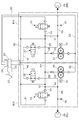
図3は、実施例1における前輪側の油圧回路図である。以下に、構成を説明する。
[Hydraulic circuit and control of front wheel side hydraulic unit]
FIG. 3 is a hydraulic circuit diagram on the front wheel side in the first embodiment. The configuration will be described below.
ブレーキペダル22を踏み込むと、マスタシリンダ23に液圧が発生する。マスタシリンダ23は、所謂タンデム型であり、油路46を介して供給する左輪側系統と、油路47を介して供給する右輪側系統にそれぞれ独立に同じ液圧を供給することができるものである。また、マスタシリンダ23にはブレーキ液を貯留するリザーバタンク24が設けられている。
When the
油路46上には遮断弁26が設けられている。油路47上には遮断弁27が設けられている。ここで、遮断弁26,27は電磁弁である。
A
遮断弁26から油路46→油路48を連通する油路上にはホイルシリンダ28(FL)が設けられている。遮断弁27から油路47→油路49を連通する油路上にはホイルシリンダ29(FR)が設けられている。
A wheel cylinder 28 (FL) is provided on the oil passage communicating from the
油路58上にはギヤポンプ30が設けられている。油路59上にはギヤポンプ31が設けられている。このギヤポンプ30,31は、コントロールユニット5からの指令値に基づいてポンプモータ32,33により駆動される。本実施例では、各輪毎にギヤポンプ30,31が設けられているが、1つの液圧源のみ備えた構成であってもよく、特に限定しない。
A
ギヤポンプ30,31に直列にワンウェイバルブ38,39が設けられている。これは、ギヤポンプ30,31を駆動して必要量の油圧を供給したときに、このワンウェイバルブ38,39を設けることでギヤポンプ30,31側に液圧が戻らないようにしている。これにより、それ以上ギヤポンプ30,31を駆動させることなく液圧を保持することが可能となり、必要最小限のギヤポンプ30,31の駆動で液圧を供給することができるよう構成されている。
One-
油路54上には減圧弁34が設けられている。油路55上には減圧弁35が設けられている。ここで、減圧弁34,35は電磁弁である。非通電のとき、遮断弁26,27は開弁し、減圧弁34,35は閉弁する。この状態でブレーキペダル22を踏む(増圧時)と、マスタシリンダ23において圧力が発生する。マスタシリンダ23において発生した圧力が油路46→前記遮断弁26→油路48の順にホイルシリンダ28に伝達される。また、油路47→前記遮断弁27→油路49の順にホイルシリンダ29に伝達される。
A
また、減圧時においては、コントロールユニット5から減圧弁34,35に制御電流が送られて減圧弁34,35の開弁量を制御することで油路50,51を介してホイルシリンダ28,29の減圧制御を行う。
Further, at the time of pressure reduction, a control current is sent from the
(ブレーキバイワイヤ制御)
本実施例において、前輪側はいわゆるブレーキバイワイヤ制御を実行できる。すなわち、運転者のキー操作によりIGN ONとされると、遮断弁26,27を閉じる。そして、運転者のブレーキ操作意図をマスタシリンダ圧等から検出し、その意図及び走行状況に応じて、ギヤポンプ30,31によって所望のブレーキ液圧を発生させるものである。尚、ブレーキ操作意図は、マスタシリンダ圧センサ、ストロークセンサ等により検出できるが、これらに限るものではなく、他の手段を用いてもよい。また、所望のブレーキ液圧は、ホイルシリンダ圧センサ40,41で検出される。
(Brake-by-wire control)
In this embodiment, the front wheel side can perform so-called brake-by-wire control. That is, when the IGN is turned ON by the driver's key operation, the
また、運転者がブレーキペダル22を踏み、前輪側のホイルシリンダ28,29に制動力が入力されている状態において、車輪速センサ等により車輪のロックを検出した場合は、前輪側ホイルシリンダ圧を制御することでABS制御を行うことができる。すなわち、遮断弁26,27を閉弁し、減圧弁34,35を開弁することで減圧、減圧弁34,35を閉弁することで液圧保持、ポンプモータ32,33、及びギヤポンプ30,31を駆動することで増圧が可能であり、ABS制御を達成できる。
Further, when the driver depresses the
また、前輪のスリップ状態を車輪速センサ等で検知した場合、前輪側ホイルシリンダ圧を制御することでTCS制御を行うことができる。すなわち、遮断弁26,27を閉弁し、ポンプモータ32,33及びギヤポンプ30,31を駆動させ、リザーバタンク24から油路46,47、ギヤポンプ30,31、油路52,53を経由して増圧、ポンプモータ32,33及びギヤポンプ30,31を停止させることで液圧保持、減圧弁34,35を開弁することで減圧が可能であり、TCS制御を達成できる。
Moreover, when the slip state of the front wheel is detected by a wheel speed sensor or the like, TCS control can be performed by controlling the front wheel side wheel cylinder pressure. That is, the
更に、ヨーレイトセンサ等、車両のスピン方向を検出するセンサを設け、上記のTCS制御と同様の制御を行うことで、スピン防止制御を行うことができる。 Further, by providing a sensor for detecting the spin direction of the vehicle, such as a yaw rate sensor, and performing the same control as the above TCS control, the spin prevention control can be performed.
以上説明したように、本実施例1においては、モータ6のロータ位置被検出部材4bを、モータ回転軸6b側に設ける代わりに、ポンプ駆動軸10aがモータ回転軸6bと嵌合する側とギヤポンプ2を挟んで反対側に配置し、このロータ位置被検出部材4bと対向する位置にロータ位置検出部材4aを配置した構成としている。これにより、ロータ位置検出部材4aはモータ6のロータの磁気的影響を受けにくくなるため、ロータ位置の検出精度の低下を抑制することができる。また、シールドを新たに設けることなく、ロータがロータ位置検出部材4aに及ぼす磁気的影響を抑制できるため、コスト増大を抑制することができる(請求項1に対応)。
As described above, in the first embodiment, instead of providing the rotor position detected
また、ロータ位置検出部材4aは複数の素子から成り、ブロック10のケース取付面15側に配置されると共に、ロータ位置検出部材4aに近接してモータ6駆動用のコントロールユニット5が配設され、ロータ位置検出部材4aの出力ライン4cがコントロールユニット5に接続している構成となっている。これにより、複数の出力ライン4cの接続を近接した位置で行うことが可能となり、接続が容易になる。また、出力ライン4cが短くなり、外乱を抑えることができるため、ロータ位置の検出精度の低下を防止することができる
The rotor
また、ケース取付面15側にギヤポンプ2から吐出された流体の油路を切り替える電磁弁3、コントロールユニット5を配置しているため、電磁弁3とコントロールユニット5が近接して配置される。よって、電磁弁3とコントロールユニット5との電気的接続を容易に行うことができる。
Further, since the
図4は、実施例2におけるブレーキ液圧制御ユニットを表す図である。尚、基本的構成は実施例1の図1のブレーキ液圧制御ユニットと同じであるため、異なる部分についてのみ説明を行う。 FIG. 4 is a diagram illustrating a brake fluid pressure control unit according to the second embodiment. Since the basic configuration is the same as that of the brake fluid pressure control unit of FIG. 1 according to the first embodiment, only different parts will be described.
図1のブレーキ液圧制御ユニットにおいては、ロータ位置検出部材4aをポンプ駆動軸10aに取り付けた構成としている。これに対し、図4のブレーキ液圧制御ユニットにおいては、ロータ位置検出部材4aをポンプ従動軸の端部に取り付けた構成としている。ここで、図4においては、ポンプ駆動軸10aの上下方向を逆に配置することでポンプ従動軸10bを構成することができる。つまり、ポンプ駆動軸10aとポンプ従動軸10bは共通の部品を用いることができる。これにより、部品点数を少なくすることが可能となり、コスト削減を図ることができる。尚、本発明の液圧制御装置は、ブレーキ液圧制御ユニット以外にもパワーステアリング装置の液圧制御ユニットに用いても良い。
In the brake fluid pressure control unit of FIG. 1, the rotor
更に、上記各実施例から把握しうる請求項以外の技術的思想について、以下にその効果と共に記載する。 Further, technical ideas other than the claims that can be grasped from the respective embodiments will be described below together with the effects thereof.
(イ) 請求項1記載のブレーキ液圧制御装置において、
前記位置センサは複数の素子からなり前記ハウジングの第1の側面に対応する第2の側面側に配置されると共に、前記位置センサに近接してモータ駆動用コントロールユニットが配設され、前記位置センサの出力ラインはコントロールユニットに接続することを特徴とするブレーキ液圧制御装置。
(A) In the brake fluid pressure control device according to
The position sensor includes a plurality of elements and is disposed on a second side surface corresponding to the first side surface of the housing, and a motor drive control unit is disposed in the vicinity of the position sensor. The brake fluid pressure control device is characterized in that the output line of is connected to a control unit.
ロータ位置検出部材4aが複数の出力ライン4cの接続を近接した位置で行うことができるため、接続が容易であり、また出力ライン4cが短いことから外乱を受けにくく、ロータ位置の検出精度の低下を防止することができる。
Since the rotor
(ロ) 請求項1または上記(イ)記載のブレーキ液圧制御装置において、
前記第2の側面側に前記ポンプから吐出された流体の油路を切り替える電磁弁を配置し、前記第2の側面と前記コントロールユニットが接続されることを特徴とするブレーキ液圧制御装置。
(B) In the brake fluid pressure control device according to
A brake hydraulic pressure control device, wherein an electromagnetic valve for switching an oil passage of fluid discharged from the pump is disposed on the second side surface, and the second side surface and the control unit are connected.
電磁弁3とコントロールユニット5が近接して配置される構成であるため、電磁弁3とコントロールユニット5との接続を容易に行うことができる。
Since the
1 ブロック
2 ギヤポンプ
3 電磁弁
4 位置センサ
4a ロータ位置検出部材
4b ロータ位置被検出部材
4c 出力ライン
5 コントロールユニット
6 モータ
6a モータフランジ部
6b モータ駆動軸
6c ボルト
7 サブブロック
7a 収装孔
7b シール孔
7c 軸受け孔
7d 蓋体
8 連結部
9a,9b オイルシール
10a ポンプ駆動軸
10b ポンプ従動軸
11 モータ取付孔
11a シール孔
11b 軸受け孔
12 シリンダ孔
14 モータ取付面
15 ケース取付面
16 電気的接続部(電磁弁側)
17 ケース
18 カバー
19 電気的接続部(ロータ位置検出部側)
22 ブレーキペダル
23 マスタシリンダ
24 リザーバタンク
25 ブレーキスイッチ
26,27 遮断弁
28 ホイルシリンダ(FL)
29 ホイルシリンダ(FR)
30,31 ギヤポンプ
32,33 ポンプモータ
34,35 減圧弁
38,39 ワンウェイバルブ
40,41 ホイルシリンダ圧センサ
L/U 左輪側油圧ユニット
R/U 右輪側油圧ユニット
DESCRIPTION OF
17
22
29 Wheel cylinder (FR)
30, 31
L / U Left wheel side hydraulic unit
R / U right wheel side hydraulic unit
Claims (1)
該ハウジングの第1の側面に固定され、回転軸により前記ポンプを駆動するモータと、
前記ポンプを挟んで前記モータに対向する位置であって、前記モータの回転軸に固定された被検出部材と、
前記被検出部材に対向する位置であって、前記ハウジング側に固定され、前記被検出部材の位置を検出する検出部材と、
からなる位置センサを備えたことを特徴とする液圧制御装置。
A housing with a pump inside,
A motor fixed to the first side surface of the housing and driving the pump by a rotating shaft;
A position to be opposed to the motor across the pump, and a detected member fixed to the rotating shaft of the motor;
A detection member which is a position facing the member to be detected and is fixed to the housing side and detects the position of the member to be detected;
A hydraulic pressure control device comprising a position sensor comprising:
Priority Applications (1)
| Application Number | Priority Date | Filing Date | Title |
|---|---|---|---|
| JP2004063288A JP2005247227A (en) | 2004-03-08 | 2004-03-08 | Hydraulic control device |
Applications Claiming Priority (1)
| Application Number | Priority Date | Filing Date | Title |
|---|---|---|---|
| JP2004063288A JP2005247227A (en) | 2004-03-08 | 2004-03-08 | Hydraulic control device |
Publications (1)
| Publication Number | Publication Date |
|---|---|
| JP2005247227A true JP2005247227A (en) | 2005-09-15 |
Family
ID=35028125
Family Applications (1)
| Application Number | Title | Priority Date | Filing Date |
|---|---|---|---|
| JP2004063288A Pending JP2005247227A (en) | 2004-03-08 | 2004-03-08 | Hydraulic control device |
Country Status (1)
| Country | Link |
|---|---|
| JP (1) | JP2005247227A (en) |
Cited By (5)
| Publication number | Priority date | Publication date | Assignee | Title |
|---|---|---|---|---|
| JP2008044471A (en) * | 2006-08-11 | 2008-02-28 | Advics:Kk | Brake hydraulic control unit for vehicle |
| JP2008056199A (en) * | 2006-09-04 | 2008-03-13 | Advics:Kk | Brake hydraulic control unit for vehicle |
| JP2008254733A (en) * | 2007-04-05 | 2008-10-23 | Fte Automotive Gmbh | Anti-lock hydraulic brake device for motorized two-wheeled vehicle with |
| JP2015189366A (en) * | 2014-03-28 | 2015-11-02 | 株式会社デンソー | Actuator for brake liquid pressure control |
| CN115428309A (en) * | 2020-01-09 | 2022-12-02 | Lg伊诺特有限公司 | Electrical machine |
-
2004
- 2004-03-08 JP JP2004063288A patent/JP2005247227A/en active Pending
Cited By (6)
| Publication number | Priority date | Publication date | Assignee | Title |
|---|---|---|---|---|
| JP2008044471A (en) * | 2006-08-11 | 2008-02-28 | Advics:Kk | Brake hydraulic control unit for vehicle |
| CN101121404B (en) * | 2006-08-11 | 2012-06-27 | 株式会社爱德克斯 | Brake hydraulic pressure control unit for vehicle |
| JP2008056199A (en) * | 2006-09-04 | 2008-03-13 | Advics:Kk | Brake hydraulic control unit for vehicle |
| JP2008254733A (en) * | 2007-04-05 | 2008-10-23 | Fte Automotive Gmbh | Anti-lock hydraulic brake device for motorized two-wheeled vehicle with |
| JP2015189366A (en) * | 2014-03-28 | 2015-11-02 | 株式会社デンソー | Actuator for brake liquid pressure control |
| CN115428309A (en) * | 2020-01-09 | 2022-12-02 | Lg伊诺特有限公司 | Electrical machine |
Similar Documents
| Publication | Publication Date | Title |
|---|---|---|
| CN113573955B (en) | Actuating device for a fully or partially hydraulically operated braking system for a vehicle | |
| CN111936378B (en) | Hydraulic control unit for bicycle | |
| JP5498541B2 (en) | Braking force generator for vehicle | |
| JP6007047B2 (en) | ABS hydraulic unit | |
| US10293798B2 (en) | Braking system with selective braking backup system | |
| JP4923839B2 (en) | Brake hydraulic pressure control unit for vehicles | |
| JP5195360B2 (en) | Brake hydraulic pressure control device | |
| EP3854643B1 (en) | Brake fluid pressure control device | |
| CN105722736A (en) | Brake device | |
| US9061670B2 (en) | Hydraulic vehicle brake system | |
| US20090189440A1 (en) | Brake hydraulic pressure control device | |
| JP6394562B2 (en) | Brake control device for vehicle | |
| JP2015071382A (en) | Vehicular brake force generation device | |
| JP5780926B2 (en) | Brake device for vehicle | |
| JP2009035031A (en) | Brake device | |
| JP2005349985A (en) | Vehicle braking device | |
| JP5283301B2 (en) | Brake hydraulic pressure control device | |
| JPWO2005039947A1 (en) | Anti-lock brake control device and anti-lock brake system equipped with the anti-lock brake control device | |
| JP4355271B2 (en) | Hydraulic control device | |
| WO2018078475A1 (en) | Brake hydraulic pressure control unit, brake system for motorcycle, and motorcycle | |
| JP2006175905A (en) | Brake fluid pressure control device for vehicle | |
| JPH07257336A (en) | Braking force control device | |
| JP2005231395A (en) | Brake hydraulic pressure control device | |
| JP5491813B2 (en) | Brake hydraulic pressure control device for vehicles | |
| WO2025166278A1 (en) | Fail-operational steer-by-wire steering system |
Legal Events
| Date | Code | Title | Description |
|---|---|---|---|
| RD04 | Notification of resignation of power of attorney |
Free format text: JAPANESE INTERMEDIATE CODE: A7424 Effective date: 20051114 |
|
| A621 | Written request for application examination |
Free format text: JAPANESE INTERMEDIATE CODE: A621 Effective date: 20060914 |
|
| A977 | Report on retrieval |
Free format text: JAPANESE INTERMEDIATE CODE: A971007 Effective date: 20080827 |
|
| A131 | Notification of reasons for refusal |
Free format text: JAPANESE INTERMEDIATE CODE: A131 Effective date: 20080909 |
|
| A02 | Decision of refusal |
Free format text: JAPANESE INTERMEDIATE CODE: A02 Effective date: 20090127 |