JP2005271237A - Inkjet recording device - Google Patents
Inkjet recording device Download PDFInfo
- Publication number
- JP2005271237A JP2005271237A JP2004084081A JP2004084081A JP2005271237A JP 2005271237 A JP2005271237 A JP 2005271237A JP 2004084081 A JP2004084081 A JP 2004084081A JP 2004084081 A JP2004084081 A JP 2004084081A JP 2005271237 A JP2005271237 A JP 2005271237A
- Authority
- JP
- Japan
- Prior art keywords
- ink
- piston
- cylinder
- recording apparatus
- sucked
- Prior art date
- Legal status (The legal status is an assumption and is not a legal conclusion. Google has not performed a legal analysis and makes no representation as to the accuracy of the status listed.)
- Pending
Links
Images

Landscapes
- Ink Jet (AREA)
Abstract
【課題】必要以上に長い時間を費やすことなく、インクジェット記録手段のインク吐出性能を回復させるためのインク吸引排出機構から排出されるインクのあふれや飛散を防止する。
【解決手段】ピストン231の往方向移動によってシリンダ内にインクを吸引し、ピストンの復方向移動によってシリンダ内のインクを排出するインク吸引排出機構を構成するシリンダポンプ230を備え、シリンダ内に吸引されるインクの量が多いほど、ピストンの復方向移動の移動速度を遅くするように制御する。
【選択図】 図1To prevent overflow and scattering of ink discharged from an ink suction / discharge mechanism for recovering ink discharge performance of an ink jet recording means without spending an unnecessarily long time.
SOLUTION: A cylinder pump 230 constituting an ink suction / discharge mechanism that sucks ink into a cylinder by a forward movement of a piston 231 and discharges ink in the cylinder by a backward movement of the piston is sucked into the cylinder. Control is performed so that the moving speed of the backward movement of the piston decreases as the amount of ink to be increased.
[Selection] Figure 1
Description
本発明は、記録手段から被記録材へインクを吐出して記録を行うインクジェット記録装置に関し、詳しくは、シリンダ内におけるピストンの移動によってインクを吸引、排出するインク吸引排出機構を備えたインクジェット記録装置に関する。 The present invention relates to an ink jet recording apparatus that performs recording by discharging ink from a recording means to a recording material, and more specifically, an ink jet recording apparatus having an ink suction / discharge mechanism that sucks and discharges ink by movement of a piston in a cylinder. About.
記録手段から被記録材へインクを吐出して記録するインクジェット記録装置は、プリンタ等として一般に普及している。インクジェット記録装置においては、吐出口(ノズル口)からインクを吐出することから、インク中溶媒の蒸発によって吐出口の近傍のインクの粘度が上昇したり、吐出口に埃等の異物が付着したりすると、インク滴が吐出しないいわゆる不吐出や、インク滴の吐出方向が偏向するいわゆるヨレといった不具合が発生することがある。そのため、インクジェット記録装置においては、吐出口からのインク中溶媒の蒸発を抑えたり、吐出口への異物の付着を防止するために吐出口を覆う(キャッピングする)ためのキャッピング機構が装備されており、さらに、増粘してしまったインクを吐出口から吸引排出するための吸引回復機構を装備することも行われている。 2. Description of the Related Art Inkjet recording apparatuses that record by discharging ink from a recording unit to a recording material are widely used as printers and the like. In an ink jet recording apparatus, ink is ejected from an ejection port (nozzle port), so that the viscosity of ink near the ejection port increases due to evaporation of the solvent in the ink, and foreign matter such as dust adheres to the ejection port. Then, there may be problems such as so-called non-ejection in which ink droplets are not ejected and so-called twisting in which the ejection direction of ink droplets is deflected. Therefore, the ink jet recording apparatus is equipped with a capping mechanism for covering (capping) the ejection port in order to suppress evaporation of the solvent in the ink from the ejection port and to prevent foreign matter from adhering to the ejection port. Further, a suction recovery mechanism for sucking and discharging the thickened ink from the discharge port is also provided.
前記吸引回復機構を備えたインクジェット記録装置には、一般に、吸引排出されるインク等の液体を吸収保持するための液体保持手段(廃インク保持手段)が設けられている。近年、デジタルカメラ等で撮影した画像をL判サイズ等の比較的小さな用紙にプリントすることを主な用途とする、かなり小型のインクジェット記録装置の製品化が要望されるようになってきている。このようなインクジェット記録装置においては、製品を小型化するために、上記液体保持手段も小型化することが要請されている。 Generally, an ink jet recording apparatus provided with the suction recovery mechanism is provided with a liquid holding means (waste ink holding means) for absorbing and holding a liquid such as ink that is sucked and discharged. In recent years, there has been a demand for commercialization of a considerably small-sized ink jet recording apparatus whose main application is to print an image photographed by a digital camera or the like on a relatively small sheet of L size or the like. In such an ink jet recording apparatus, it is required to reduce the size of the liquid holding means in order to reduce the size of the product.
しかしながら、上記廃インク保持手段(廃インク吸収保持部材等)の小型化には限界があるため、この廃インク保持手段をインクジェット記録装置に対して着脱自在にして交換可能にしたインクジェット記録装置が提案されている。このようなインクジェット記録装置は、例えば特開平3−5159号公報に開示されている。廃インク保持手段をインクジェット記録装置に対して着脱自在に構成した場合、廃インク保持手段とインクジェット記録装置との接合部において廃インクの溢れや飛散が生じてしまうおそれがある。そこで、特開平3−5159号公報には、インクジェット記録装置に対して着脱自在に構成された廃インク容器の、廃インク管の端部が装着される部位に、インク吸収部材を用いて廃インク管の端部を把持する接続構造を設け、廃インク容器とインクジェット記録装置との接合部における廃インクの飛散を防止するようにした構成も開示されている。
しかしながら、上記のインクジェット記録装置においても、多量の廃インクを短い時間内に排出すると、上記廃インク保持手段への廃インクの排出速度が、上記インク吸収部材から成る接続構造の内部における廃インクの浸透速度を上回ってしまい、廃インク保持手段とインクジェット記録装置との接合部において廃インクの溢れや飛散が発生することがある。一方、製品の小型化のために、前記吸引回復機構におけるインクの吸引排出手段としてピストンがシリンダ内を往復移動するシリンダポンプ(液体吸引排出装置)を採用したインクジェット記録装置においては、ピストンの往方向移動によって吐出口からインクを吸引し、復方向移動によって吸引されたインクを廃インク保持手段へ排出するように構成することが提案されている。 However, also in the above-described ink jet recording apparatus, when a large amount of waste ink is discharged within a short time, the discharge speed of the waste ink to the waste ink holding means is reduced to the waste ink inside the connection structure composed of the ink absorbing member. The permeation speed may be exceeded, and waste ink may overflow or scatter at the junction between the waste ink holding means and the ink jet recording apparatus. On the other hand, in an ink jet recording apparatus that employs a cylinder pump (liquid suction / discharge device) in which a piston reciprocates in a cylinder as ink suction / discharge means in the suction recovery mechanism in order to reduce the size of the product, the forward direction of the piston It has been proposed that the ink is sucked from the ejection port by the movement, and the ink sucked by the backward movement is discharged to the waste ink holding means.
しかし、このような構成においては、着脱自在に構成された廃インク保持手段とインクジェット記録装置との接合部における廃インクの溢れや飛散が生じないように、常に(シリンダ内に吸引されるインクの量が少ない場合においても)シリンダ内におけるピストンの復方向移動の移動速度を遅くしておくと、ピストンの復方向移動の移動時間がインクジェット記録装置のスループットに悪影響を与えることになる。そのため、シリンダ内に吸引されるインクの量が少ない場合などにおいて、インクジェット記録装置のプリント時間が必要以上に長くなってしまい、スループットが低下するという不具合が発生することがある。 However, in such a configuration, the waste ink is not always overflowed or scattered at the joint between the detachable waste ink holding means and the ink jet recording apparatus (the ink sucked into the cylinder). If the moving speed of the backward movement of the piston in the cylinder is slowed (even when the amount is small), the moving time of the backward movement of the piston will adversely affect the throughput of the ink jet recording apparatus. Therefore, when the amount of ink sucked into the cylinder is small, the printing time of the ink jet recording apparatus becomes longer than necessary, which may cause a problem that the throughput is lowered.
本発明は、このような課題を解決するためになされたものであり、その目的は、シリンダ内におけるピストンの移動によってインクを吸引、排出するインク吸引排出機構を備えたインクジェット記録装置において、必要以上に長い時間を費やすことなく、インク吸引排出機構から排出されるインクのあふれや飛散を防止することができる構成を提供することである。 The present invention has been made to solve such problems, and an object of the present invention is to provide an ink jet recording apparatus having an ink suction / discharge mechanism that sucks and discharges ink by movement of a piston in a cylinder. It is to provide a configuration capable of preventing overflow and scattering of ink discharged from the ink suction / discharge mechanism without spending a long time.
本発明は、上記目的を達成するために、記録手段から被記録材へインクを吐出して記録を行うインクジェット記録装置において、前記記録手段のインク吐出性能を回復させるために、ピストンの往方向移動によってシリンダ内にインクを吸引し、前記ピストンの復方向移動によって前記シリンダ内のインクを排出するインク吸引排出機構を備え、前記シリンダ内に吸引されるインクの量に応じて、前記ピストンの前記復方向移動の移動態様を制御することを特徴とする。 In order to achieve the above object, the present invention provides an ink jet recording apparatus that performs recording by ejecting ink from a recording means to a recording material. In order to recover the ink ejection performance of the recording means, the piston moves in the forward direction. And an ink suction / discharge mechanism for sucking ink into the cylinder and discharging the ink in the cylinder by the backward movement of the piston, and according to the amount of ink sucked into the cylinder. It controls the movement mode of the direction movement.
本発明によれば、シリンダ内におけるピストンの移動によってインクを吸引、排出するインク吸引排出機構を備えたインクジェット記録装置において、必要以上に長い時間を費やすことなく、インク吸引排出機構から排出されるインクのあふれや飛散を防止することができる。 According to the present invention, in an ink jet recording apparatus having an ink suction / discharge mechanism that sucks and discharges ink by movement of a piston in a cylinder, ink discharged from the ink suction / discharge mechanism without spending more time than necessary. Overflow and scattering can be prevented.
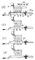
以下、図面を参照して本発明の実施の形態を具体的に説明する。なお、各図面を通して同一符号は同一又は対応部分を示す。図7は本発明を適用するのに好適なインクジェット記録装置の各動作時の状態を示す模式的側面図であり、(a)は記録中の状態を示し、(b)は記録可能状態から記録手段を上昇させた状態を示し、(c)は(b)の状態から回復装置のキャッピング機構を水平方向に移動させた状態を示し、(d)は(c)の状態から記録手段又はキャップを上下方向に移動させて吐出口面にキャップを密着させたキャッピング状態を示す。本発明を適用するのに好適なインクジェット記録装置は、記録手段(その吐出口)から記録紙等の被記録材へインクを吐出して記録を行うものである。 Embodiments of the present invention will be specifically described below with reference to the drawings. Note that the same reference numerals denote the same or corresponding parts throughout the drawings. FIG. 7 is a schematic side view showing a state during each operation of an ink jet recording apparatus suitable for applying the present invention. (A) shows a state during recording, and (b) shows recording from a recordable state. (C) shows a state in which the capping mechanism of the recovery device has been moved in the horizontal direction from the state of (b), and (d) shows the recording means or cap from the state of (c). A capping state in which the cap is brought into close contact with the discharge port surface by moving in the vertical direction is shown. An ink jet recording apparatus suitable for applying the present invention performs recording by discharging ink from a recording means (its discharge port) to a recording material such as recording paper.
図7において、4本の異なる種類のインクを吐出するラインタイプのインクジェット記録ヘッド100a、100b、100c、100dが、ヘッドホルダ12に取り付けられている。なお、本明細書においては、前記複数本の記録ヘッド100a、100b、100c、100dの全体もしくは任意の1本を指す場合は、単に記録ヘッド100で示す。
In FIG. 7, line-type
各記録ヘッド100は、被記録材Pの搬送方向Aの所定間隔ごとの位置に長手方向が該搬送方向Aと交差(通常では直交)する姿勢で取り付けられている。各記録ヘッド100の吐出口面101には、搬送方向と直交する方向に直列配列された多数(例えば1280個)の吐出口から成る吐出口列が形成されている。被記録材Pを搬送するための搬送機構は、駆動ローラ25と従動ローラ26との間に張架されたエンドレスベルトから成る搬送ベルト24を備えており、搬送モータ(不図示)で駆動ローラ25を回転駆動することで被記録材Pを矢印A方向に搬送するように構成されている。
Each
前記搬送機構の図7中の右側には、給紙トレイ27上に積載された被記録材Pを給紙ローラ28によって1枚ずつ搬送ベルト24上に供給するための給紙機構が配設されている。29は給紙トレイ27上の被記録材Pを給紙ローラ28に当接させるための押圧ばねを示す。また、前記搬送機構の図7中の左側には、搬送ベルト24から排出される記録済みの記録紙などの被記録材Pを保持するための排紙トレイ30が配設されている。図7に示すインクジェット記録装置では、ヘッド昇降機構31によってヘッドホルダ12の上下位置を調整することにより各記録ヘッド100の高さ位置を制御できるように構成されている。また、各記録ヘッド100の近傍には、各記録ヘッドの吐出口面101に当接することで対応する記録ヘッドの吐出口(吐出口列)を密閉するための複数(4個)のキャップ210を備えたキャッピング機構が配設されている。このキャッピング機構は、記録ヘッド100のインク吐出性能を維持回復するための回復装置の一部を構成している。
On the right side of the transport mechanism in FIG. 7, a paper feed mechanism for supplying the recording materials P stacked on the
図7において、(a)に示す記録動作のときには、記録ヘッド100は下降位置にあり、搬送ベルト24によって搬送される被記録材Pに向けてインクを吐出することにより画像記録(印刷、プリント)が実行される。記録動作を終えると、先ず(b)に示すようにヘッド昇降機構31の作動により記録ヘッド100を上昇させる。次いで、(c)に示すように不図示のモータによって各キャップ210を図示右方向へ所定距離だけ水平移動させることにより、各記録ヘッド100の真下に対応する各キャップ210が位置する状態にする。
In FIG. 7, during the recording operation shown in FIG. 7A, the
次いで、不図示の昇降機構によって各キャップ210を上昇させるか、もしくはヘッド昇降機構31によって各記録ヘッド100を下降させることにより、各記録ヘッドの吐出口面101にキャップ210を当接(密着)させてキャッピング状態にする。装置保管時や記録待機時などの非記録時には、キャッピング状態にして吐出口を密閉することにより、吐出口からのインク溶剤の蒸発を抑制するとともに吐出口面101の保護を図ることができる。記録を再開する場合は、以上とは逆の操作を行うことで(a)の状態にし、記録動作を開始する。
Next, each
記録ヘッド100は、記録信号に応じてエネルギーを印加することにより、複数の吐出口からインクを選択的に吐出して記録するインクジェット記録ヘッドである。また、この記録ヘッド100は、熱エネルギーを利用してインクを吐出するものであり、吐出口ごとに、熱エネルギーを発生するためのインク吐出用の電気熱変換体を備えたものである。さらに、記録ヘッド100は、前記電気熱変換体が発生する熱エネルギーによって生じる膜沸騰による気泡の成長、収縮に基づく圧力変化を利用して吐出口からインク滴を吐出、飛翔させ、被記録材に着弾させて記録を行うものである。前記インク吐出用の電気熱変換体は、各吐出口のそれぞれに対応して配設され、記録信号に応じて対応する電気熱変換体にパルス電圧を印加することにより対応する吐出口からインクを吐出するものである。
The
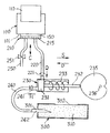
図1は本発明の実施例1に係るインクジェット記録装置の回復装置の要部構成を示す模式的縦断面図である。図1において、記録ヘッド100は、被記録材搬送方向(図7中の矢印A方向)と直交する方向、すなわち被記録材の幅方向に長い長尺部材で構成されている。この記録ヘッド100の吐出口面(記録時に被記録材Pと所定間隔をもって対向する面)101には、多数の吐出口(例えば1280個の吐出口)が直列状態で形成されている。従って、図示のインクジェット記録装置は、1ライン分の記録を一括して記録し、副走査(被記録材の紙送り)のみで被記録材Pの全領域に対する記録を行うように構成されている。なお、本実施例では、記録ヘッド100にインクを供給するためのインクタンク110は、該記録ヘッド自体に着脱自在に取り付けられている。
FIG. 1 is a schematic longitudinal cross-sectional view showing a main configuration of a recovery device of an ink jet recording apparatus according to Embodiment 1 of the present invention. In FIG. 1, the
図1において、210は記録ヘッド100の吐出口面101に当接することで吐出口を覆う(密閉する)ためのキャップであり、該キャップ210は、吐出口面101との密着性を確保するために一般的にはゴム等の弾性材料で形成されている。記録ヘッド100が図1に示すようにキャッピング可能なポジションに位置するときに、キャップ210が図1に示すように吐出口面101に密着することにより、記録ヘッド100の全ての吐出口が覆われる(キャッピングされる)。従って、キャップ210も記録ヘッド100に対応して被記録材の幅方向に長い部材で構成されている。
In FIG. 1,
キャップ210は、両矢印C方向方向に昇降可能なキャップホルダ(不図示)に装着されており、該キャップホルダを昇降駆動することにより、図示のキャッピングポジションと、キャップ210が吐出口面101から離間している離間ポジションとの間で昇降移動する。キャップ210には吸引チューブ220が接続されており、該吸引チューブ220の他端にはシリンダポンプ230が接続されている。吸引チューブ220には、流体の図1中の矢印Q方向への移動のみを許す逆止弁221が設けられている。シリンダポンプ230には流体排出用のドレイン(排出)チューブ240が接続されている。ドレインチューブ240の他端にはドレイン針242が接続されている。ドレインチューブ240にも、流体の図1中の矢印H方向の移動のみを許す逆止弁241が設けられている。
The
図1中の300は廃インクタンクである。廃インクタンク300の内部には、多孔質材等から成る液体保持手段としての廃インク吸収保持部材310が充填されている。この廃インクタンク300は記録装置に対して着脱自在に構成されている。廃インクタンク300にはドレイン開口301が設けられている。ドレイン開口301は、廃インクタンク300を記録装置に装着するときにドレイン針242を廃インク吸収保持部材310内に挿入するためのものである。廃インクタンク300には、廃インク吸収保持部材310内に吸収保持された廃インク中の蒸発成分を蒸発させるための開口302が設けられている。
In FIG. 1, 300 is a waste ink tank. The
キャップ210には大気連通チューブ250が接続されており、該大気連通チューブには大気連通弁251が設けられている。この大気連通弁251は、キャップ210が上記キャッピングポジションに位置しているときに、キャップ210と吐出口面101との間に形成されるキャップ内空間150を大気に連通させるか、大気から遮断するかを制御するためのものである。キャップ内空間150には、多孔質材等から成るインク吸収体215が充填されている。
An
シリンダ内のピストン231の往復移動は、記録装置に設けられた搬送モータの回転を利用して行われる。搬送モータの用紙搬送方向(以下、CW方向と称する)の回転とは反対方向(以下、CCW方向と称する)の回転を、ワンウエイクラッチ及びギア列等を介して回転軸236へ伝達させ、該回転軸236によって駆動されるカム235の回転に伴ってピストン軸232を駆動し、ピストン231を作動するように構成されている。この場合、カム235のカム面の形状によってピストン231の矢印Sの往方向並びに矢印Dの復方向の移動範囲が制御される。なお、ピストン231は、引っ張りばね233によって常に矢印S方向(往方向)にばね付勢されている。
The reciprocating movement of the
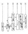
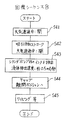
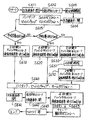
インク吸引排出機構を構成するシリンダポンプ230は、ピストン231の往方向(矢印S方向)移動によってシリンダ内に液体を吸引し、復方向(矢印D方向)移動によってシリンダ内の液体を排出する動作するものであり、本発明を適用したインク吸引排出機構230では、上記シリンダ内に吸引される液体(インク)の量に応じて、ピストン231の復方向移動の移動態様を制御するように構成されている。図2は実施例1に係るインクジェット記録装置の回復装置の回復シーケンスを示すフローチャートであり、図3は図2中の回復シーケンスAの内容を示すフローチャートであり、図4は図2中の回復シーケンスBの内容を示すフローチャートである。
The
次に、実施例1における回復動作を、図1〜図4を参照しながら説明する。図1のインクジェット記録装置にはタイマが設けられており、前回の回復シーケンス実行(回復動作)からの経過時間をカウントしている。図2において、インクジェット記録装置にプリント指令が入力される(ステップS1)と、上記タイマのカウント値を参照し(ステップS2)、該カウント値に応じて回復シーケンスA及び回復シーケンスBのいずれかを選別して実行し(ステップS3)、回復シーケンスの後にプリント(記録)を実行する(ステップS4)。 Next, the recovery operation in the first embodiment will be described with reference to FIGS. The ink jet recording apparatus of FIG. 1 is provided with a timer, and counts the elapsed time since the previous recovery sequence execution (recovery operation). In FIG. 2, when a print command is input to the ink jet recording apparatus (step S1), the count value of the timer is referred to (step S2), and either the recovery sequence A or the recovery sequence B is determined according to the count value. After selecting and executing (step S3), printing (recording) is executed after the recovery sequence (step S4).
具体的には、上記カウント値が例えば120時間(5日)未満である場合(短い場合)には回復シーケンスAを実行し、120時間以上である場合(長い場合)には回復シーケンスBを実行し、その後にプリントを実行する。プリント実行後には再度のプリント指令の入力を例えば30秒間待つが、30秒間経過してもプリント指令が入力されない場合には、記録装置の各構成要素をホームポジションに戻し(ステップS5)、さらに再度のプリント指令の入力を待つ(ステップS6)。次に、上記回復シーケンスA及び上記回復シーケンスBの内容を説明する。なお、以下の説明においては、上記プリント指令が入力される前のインクジェット記録装置の各構成要素は、それぞれのホームポジションに位置しているものとする。 Specifically, for example, when the count value is less than 120 hours (5 days) (when it is short), the recovery sequence A is executed, and when it is 120 hours or more (when it is long), the recovery sequence B is executed. Then, printing is performed. After printing, for example, it waits for another 30 seconds to input a print command, but if no print command is input after 30 seconds, each component of the recording apparatus is returned to the home position (step S5), and again. The input of the print command is awaited (step S6). Next, the contents of the recovery sequence A and the recovery sequence B will be described. In the following description, it is assumed that each component of the ink jet recording apparatus before the print command is input is located at each home position.
主な構成要素のホームポジションは以下のとおりである。すなわち、記録ヘッド100、キャップ210、ピストン231及びカム235については図1に示す位置がホームポジションであり、大気連通弁251については弁開放状態がホームポジションである。図3の回復シーケンスAにおいて、上記タイマのカウント値が120時間未満であった場合には、まずキャップ210を吐出口面101から離間した離間ポジションへ移動させる(ステップS31)。そして、記録ヘッド100を駆動することにより予備吐出を実行する(ステップS32)。この予備吐出は、記録ヘッド100の1280個の吐出口のそれぞれからキャップ210内のインク吸収体215に向けて、1000滴ずつのインク滴を吐出させる動作によって行う。
The home positions of the main components are as follows. That is, the position shown in FIG. 1 is the home position for the
前回の回復シーケンス実行からの経過時間が120時間未満と短い場合には、吐出口からのインク中溶媒の蒸発量がわずかであるため、回復シーケンスAにおける予備吐出によって吐出口近傍の極少量の増粘インクを排出するだけで、記録ヘッド100のインク吐出性能を回復させることができる。図3において、予備吐出を実行した後、搬送モータ(図7中の駆動モータM3に相当)を前記CCW方向に回転させ、カム235を図1の位置から180度だけ回転させ、ピストン231を上死点(図1に示す左側のホームポジション)から下死点(図1中の右側の終点)まで移動させる。この間のピストンの往方向移動によって、キャップ210内のインク吸収体215に吸収されているインク(予備吐出による廃インク)を、シリンダポンプ230のシリンダ内に吸引する(ステップS33)。
When the elapsed time from the previous recovery sequence execution is as short as less than 120 hours, the amount of evaporation of the solvent in the ink from the ejection port is small, and therefore, a very small increase in the vicinity of the ejection port is caused by the preliminary ejection in the recovery sequence A. The ink ejection performance of the
この間の搬送モータの回転速度は、例えば2秒間でピストン231が上死点(図1中の左側位置=ホームポジション)から下死点まで移動するのに対応する回転速度である。そして、この間のピストン231の往方向移動は液体を吸引する吸引方向ストロークである。また、この間の搬送モータの回転速度は一定であり、ピストン231の移動速度も略一定である。また、ピストン231の吸引方向ストロークによってシリンダポンプ230のシリンダ内に吸引されるインクの量は、記録ヘッド100の各吐出口から予備吐出されたインク滴の総数である1280000滴に、インク滴1滴あたりの体積を乗じた量であり、本実施例では0.0064mlになる。
The rotation speed of the transport motor during this period is a rotation speed corresponding to the movement of the
上記吸引方向ストロークを終了した後、直ちに、搬送モータをさらにCCW方向に回転させ、カム235をさらに180度だけ回転させる。すなわち、ピストン231が下死点から上死点まで復方向移動する分だけカム235を回転させることにより、シリンダ内に吸引されたインクを廃インクタンク300内へ排出する(ステップS34)。このときの搬送モータの回転速度も、例えば2秒間でピストン231が下死点から上死点まで移動するのに対応する回転速度であり、この間の復方向移動による排出行程をドレイン方向ストロークと称する。この間の搬送モータの回転速度は一定であり、ピストン231の移動速度は略一定である。
Immediately after completing the suction direction stroke, the transport motor is further rotated in the CCW direction, and the
また、上記復方向移動(ドレイン方向ストローク)によって廃インクタンク300内へ排出される廃インクの量は、ピストン231の往方向移動(吸引方向ストローク)によってシリンダ内に吸引されたインク量の0.0064mlである。なお、ピストン231のドレイン方向ストロークによってシリンダ内から排出される流体(インク+空気)の量は例えば2mlに設定されている。したがって、上述のように2秒間でドレイン方向ストロークを行った場合の、シリンダポンプ230から廃インクタンク300へ排出される流体(インク+空気)の排出速度は1ml/秒である。
Further, the amount of waste ink discharged into the
インク吸引排出機構を構成するシリンダポンプ230に吸引されるインクの量が0.0064mlと少ない場合には、1ml/秒という比較的速い排出速度で流体(インク+空気)を排出しても、廃インクタンク300とインクジェット記録装置との接合部、すなわちドレイン開口301の近傍部における廃インクの溢れや飛散が発生することはなかった。以上の回復シーケンスAを終了した後、図2中のプリント実行(ステップS4)に進む。なお、本実施例では、搬送モータのCCW方向回転を利用してピストン231を往復移動させているので、ピストン231の移動を停止させない限り、搬送モータ(図7中の搬送機構駆動モータM3に相当)をCW方向(被記録材搬送方向)に回転させることはできない。つまり、ピストン231の移動を停止させなければ、プリント実行に移ることはできない。
If the amount of ink sucked by the
次に前記回復シーケンスBについて説明する。図4の回復シーケンスBにおいて、上記タイマのカウント値が例えば120時間以上であった場合には、吐出口からのインク中溶媒の蒸発量が多くなるため、シリンダポンプ230を用いて記録ヘッド100の吐出口から吐出口近傍の増粘インクを吸引排出する。具体的には、例えば0.2mlのインクを吸引排出することにより記録ヘッド100のインク吐出性能を回復させることができる。そこで、図4の回復シーケンスBにおいては、図1の状態から大気連通弁251を閉じ(ステップS41)、搬送モータをCCW方向に回転させることによりカム235を180度だけ回転させる。すなわち、ピストン231の往方向移動による吸引方向ストロークを行って、記録ヘッド100の吐出口からインクを吸引する。
Next, the recovery sequence B will be described. In the recovery sequence B of FIG. 4, when the count value of the timer is, for example, 120 hours or more, the amount of solvent in the ink from the ejection port increases, so the
この間(ピストン231が吸引方向ストロークを行っている間)に、所定のタイミング(例えば吸引されるインクの量が約0.2mlとなるタイミング)で、大気連通弁251を開放する(ステップS42)。大気連通弁251を開放した後の吸引行程では、大気連通チューブ250を介してキャップ内空間150内へ流入してくる空気とともに、インク吸収体215内に吸収されているインク(吐出口から吸引されたインク)をシリンダポンプ230のシリンダ内へ吸引する。このようなインク吸引を空吸引と称する。なお、この間(吸引方向ストロークの間)の搬送モータの回転速度は、回復シーケンスAにおける回転速度と同一である。
During this time (while the
ステップS42を終了した後、直ちに、搬送モータをさらにCCW方向に回転させ、カム235を180度だけさらに回転させる。すなわち、ピストン231の復方向移動によるドレイン方向ストロークを行って、シリンダポンプ230のシリンダ内に吸引されたインクを廃インクタンク300内へと排出する(ステップS43)。このドレイン方向ストロークの間の搬送モータの回転速度を回復シーケンスAにおける回転速度と同一とすると、ドレイン開口301近傍部において廃インクの飛散が生じることがあるため、回復シーケンスBにおいては、この間の搬送モータの回転速度を回復シーケンスAにおける回転速度の約半分の速度に選定した。
Immediately after step S42 is completed, the transport motor is further rotated in the CCW direction, and the
従って、このときのドレイン方向ストロークに要する時間は約4秒であり、流体(インク+空気)の排出速度は約0.5ml/秒である。また、このときの廃インクタンク300内へ排出される廃インクの量は、上記ピストン231の吸引方向ストロークによって記録ヘッド100の吐出口から吸引されたインクの量と略同じであり、約0.2mlである。つまり、回復シーケンスAの場合の約0.00064mlより多くなっている。シリンダポンプ230内に吸引されるインクの量が約0.2mlと多くなった場合には、回復シーケンスAにおける約1ml/秒の排出速度に比べ、約0.5ml/秒という遅い流体(インク+空気)排出速度に設定される。このように、シリンダ内に吸引されるインク量が多くなった場合には、ピストン231の復方向移動(ドレイン方向ストローク)の移動速度を遅くして、廃インクを廃インクタンク300内への遅い速度で排出することにより、ドレイン開口301近傍部における廃インクの溢れや飛散を防止することができた。
Accordingly, the time required for the stroke in the drain direction at this time is about 4 seconds, and the discharge speed of the fluid (ink + air) is about 0.5 ml / second. In addition, the amount of waste ink discharged into the
インク吸引排出機構を構成するシリンダポンプ230の内部に吸引されたインクを廃インクタンク300内へ排出した後は、キャップ210を離間ポジションに移動させ(ステップS44)、回復機構に通常設けられている周知のワイピング手段(拭き取り清掃手段)等によるクリーニング動作を行った(ステップS45)後、回復シーケンスBを終了する。以上の回復シーケンスBを終了した後、図2中のプリント実行(ステップS4)に進む。以上のように、シリンダポンプ230内に吸引されるインクの量に応じて、ピストン231のドレイン方向ストロークの速度を制御することによって、プリント時間(プリント指令入力からプリント終了までの時間)を必要以上に長くすることなく、廃インクタンク300とインクジェット記録装置との接合部における廃インクの溢れや飛散を防止することができる。なお、回復シーケンスBを実行する場合も、前述の回復シーケンスAの場合と同様、搬送モータのCCW方向回転を利用してピストン231を往復移動させているので、ピストン231の移動を停止させない限り、プリント実行に移ることはできない。
After the ink sucked into the
実施例1においては、吸引方向ストロークによってシリンダ内に吸引されるインクが、記録ヘッドが吐出したインクであるか、記録ヘッドの吐出口から吸引されるインクであるかに起因するインク吸引量(多量か少量か)に応じて、ピストン231のドレイン方向の速度制御を行う例について説明したが、実施例2は、記録ヘッドの吐出口から吸引されるインクの量(多量か少量か)に応じて、ピストンのドレイン方向ストロークの移動態様を制御するものであり、以下この実施例2について説明する。
In the first embodiment, the amount of ink suction (a large amount) caused by whether the ink sucked into the cylinder by the stroke in the suction direction is the ink ejected by the recording head or the ink sucked from the ejection port of the recording head. In the second embodiment, the speed control in the drain direction of the
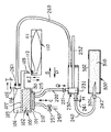
図5は本発明の実施例2に係るインクジェット記録装置の回復装置の要部構成を示す模式的縦断面図である。なお、図5においては、図1中の各部と対応する部分はそれぞれ同一符号で示されており、互いに対応する部分は実質的に同じ機能構成を有している。図5のインクジェット記録装置においては、記録装置の小型化を図るため、ピストン231の矢印D方向(ドレイン方向)のストロークによって、シリンダ内のインクを廃インクタンク300内へ排出する動作と、インクタンク110のインク袋111内から記録ヘッド100へのインク供給の動作と、を同時に行うように構成されている。
FIG. 5 is a schematic longitudinal cross-sectional view showing the main configuration of the recovery device of the ink jet recording apparatus according to Embodiment 2 of the present invention. In FIG. 5, parts corresponding to those in FIG. 1 are denoted by the same reference numerals, and parts corresponding to each other have substantially the same functional configuration. In the ink jet recording apparatus of FIG. 5, in order to reduce the size of the recording apparatus, the operation of discharging the ink in the cylinder into the
まず、インク袋111内から記録ヘッド100へインクを供給するためのインク供給シーケンス(以下、ピットインシーケンスと称する)について説明する。なお、本実施例においては、記録装置の各構成要素は、ピットインシーケンスをスタートする前にはホームポジション(図5に示すポジション)に位置しているものとする。ただし、インク吸引排出機構を構成するシリンダポンプ230のピストン231は、ピットインシーケンスをスタートする前には、矢印S方向に移動した下死点に位置しているものとする。また、大気連通弁251については、図5のホームポジションでは弁開放状態になっている。なお、ピストン231の往復移動は、専用のポンプモータ(不図示)の正逆回転によって、ギア列等の伝動機構及びピストン軸232を介して行われる。
First, an ink supply sequence (hereinafter referred to as a pit-in sequence) for supplying ink from the ink bag 111 to the
ピットインシーケンス(インク供給シーケンス)を実行する場合、不図示の着脱機構によって、インク袋111が設けられたインクタンク110を図5中の矢印J方向に移動させ、記録ヘッド100に設けられたピットイン針(中空針)109をインクタンク110に設けられたゴム栓112に刺し通す。これによって、インク袋111の内部が、記録ヘッド100のリザーブタンク103に連通するジョイントポジションの状態となる。前記リザーブタンク103の内部には、多孔質材等から成るインク吸収部材102が充填されている。インク袋111とリザーブタンク103とをジョイントポジションにすると同時に、シリンダポンプ230に接続されたピットインチューブ260の他端を記録ヘッド100に接続させてピットインポジションの状態にする。
When a pit-in sequence (ink supply sequence) is executed, the
記録ヘッド100には、リザーブタンク103と気液分離膜107で仕切られたピットイン室107が設けられており、該ピットイン室107の壁面には、ピットイン口104を有するピットイン形成面105が設けられている。上記ピットインチューブ260のピットインポジションの状態は、ピットインチューブ260の記録ヘッド100側の端部に設けられたゴム等の弾性材料から成るピットインキャップ261を、不図示の着脱機構によって矢印P方向に移動させ、ピットイン形成面105のピットイン口104の周りに密着させることによって実現される。こうして不図示の着脱機構によってジョイントポジション及びピットインポジションを完成させた後、上記ポンプモータを回転させて、ピストン231を下死点から上死点へ矢印D方向に移動させ、図5に示すようなホームポジションの状態にする。
The
このピストン231の矢印D方向(ドレイン方向)の移動によって、ピットイン室106内の空気がシリンダポンプ230のシリンダ内へと吸引され、ピットイン室106内が減圧されて負圧状態になる。すると、気液分離膜107がピットイン室106側へ撓むことによってリザーブタンク103の内容積が増加し、その分リザーブタンク103内が減圧されて負圧状態になる。ここで、気液分離膜107は気体は通過できるが液体は通過できない膜部材で構成されている。従って、リザーブタンク103内が減圧されることで、インクタンク110のインク袋111内のインクがゴム栓112及びピットイン針109を通ってリザーブタンク103内へ供給される。リザーブタンク103に供給されてくるインクは、インクは気液分離膜107を通過できないため、該リザーブタンク103内に充満された状態となって、インクの供給が停止される。
By the movement of the
その後、インクタンク110を図5中の矢印K方向に移動させて離間状態にするとともに、ピットインキャップ261を図5中の矢印T方向に移動させて離間状態とすることにより、ホームポジション(図5に示した位置)に戻す。以上のようなピットインシーケンス(インク供給シーケンス)によって、インク袋111内のインクが記録ヘッド100のリザーブタンク103内へ供給される。なお、インク袋111を有するインクタンク110は、インクジェット記録装置に対して着脱自在に構成されている。また、インクタンク110は、廃インクタンク300と一体構成にしても良い。図5の実施例2に係るインクジェット記録装置は、以上説明した点で前述の実施例1に係るインクジェット記録装置と相違するが、その他の点では実質的に同じ構成を有しており、それぞれ対応する部分を同一符号を示し、それらの詳細説明は省略する。
Thereafter, the
図6は実施例2に係るインクジェット記録装置の回復装置の回復シーケンス(回復シーケンスC)を示すフローチャートである。次に、図5及び図6を参照して実施例2における回復動作を説明する。なお、本実施例でも、インクジェット記録装置の各構成要素は、回復シーケンスをスタート前にはそれぞれ前述のホームポジションに位置しているものとする。本実施例でも実施例1の場合と同様のタイマが設けられており、本実施例では、プリント指令入力時にタイマのカウント値が1200時間(50日)以上であった場合に、図6の回復シーケンスCを実行して、プリント実行に移る。 FIG. 6 is a flowchart illustrating a recovery sequence (recovery sequence C) of the recovery device of the inkjet recording apparatus according to the second embodiment. Next, the recovery operation according to the second embodiment will be described with reference to FIGS. In this embodiment as well, each component of the ink jet recording apparatus is assumed to be located at the above-described home position before starting the recovery sequence. In this embodiment, the same timer as that in the first embodiment is provided. In this embodiment, when the count value of the timer is 1200 hours (50 days) or more when a print command is input, the recovery shown in FIG. The sequence C is executed and the printing is executed.
図5に示したようなインクジェット記録装置においては、上記タイマのカウント値が1200時間以上であった場合、吐出口からのインク中溶媒の蒸発に加えて、ピットイン針109及びピットイン口104からもインク中の溶媒が蒸発するため、記録ヘッド100のリザーブタンク103内のインクはかなり増粘して高粘度になっている。そのため、回復シーケンスCでは、一旦、リザーブタンク103内のインクを全て吸引排出してしまうことで、記録ヘッド100のインク吐出性能を回復させる方法が採られる。
In the ink jet recording apparatus as shown in FIG. 5, when the count value of the timer is 1200 hours or more, in addition to the evaporation of the solvent in the ink from the ejection port, the ink is also ejected from the pit-in
図6の回復シーケンスCにおいては、まず、大気連通弁251を閉じ(ステップS601)、次に、前記ポンプモータを回転させてピストン231を上死点(ホームポジション=図5に示した位置)から下死点まで矢印S方向へ移動させる。すなわち、シリンダポンプ230において、ピストン231を往方向に移動させることで吸引方向ストロークを行う(ステップS602)。このときのポンプモータの回転速度は、例えば約2秒間で吸引方向ストロークを行うのに相当する回転速度に設定される。なお、この間のポンプモータの回転速度は一定であり、ピストン231の移動速度も略一定である。また、このピストン231が矢印S方向に往方向移動するときのポンプモータの回転方向をCW方向と称する。ステップS602の吸引方向ストロークを行った後、約10秒間待機し(ステップS603)、その後、ステップS601で閉じ状態にした大気連通弁251を開く(ステップS604)。
In the recovery sequence C of FIG. 6, first, the
このステップS601〜S604によって、リザーブタンク103内のインクは全てシリンダポンプ230のシリンダ内に吸引される(以下、これを全吸引と称する)。ところで、実施例2に係るインクジェット記録装置においては、リザーブタンク103内のインク量(以下、QRTと称する)を次のように管理している。第1に、上述したピットインシーケンス後のQRTは、リザーブタンク103の容積からインク吸収部材102の体積を減じた量である約1.5mlとする。第2に、プリント及び前述の予備吐出等で記録ヘッド100の吐出口からインクが吐出された場合は、吐出されたインク滴の数をカウントし、インク滴1滴あたりの体積にカウント値を乗じた量を、QRTからさらに減じた値をリザーブタンク103内のインク量とする。
Through these steps S601 to S604, all the ink in the
第3に、実施例1における回復シーケンスBで説明したような所定の吸引シーケンスに従った(記録ヘッド100の吐出口からの)インク吸引を行った場合には、所定の吸引インク量を上記QRTからさらに減ずる。第4に、プリント指令の入力後には、前述のタイマからのカウント値に単位時間あたりのインク中溶媒の蒸発量を乗じた値を、上記QRTから減ずる。以上のようにQRTを管理しているので、上記全吸引の前のQRTの値も判っている。従って、上記全吸引によってシリンダポンプ230内に吸引されるインクの量(以下、全吸引量と称する)も、上記全吸引の前のQRTの値として判っている。図6の回復シーケンスCにおいては、この全吸引量(リザーブタンク103から吸引される全てのインク量)に応じて、ピストン231のドレイン方向への移動態様が制御される。
Third, when ink suction (from the ejection port of the recording head 100) is performed according to a predetermined suction sequence as described in the recovery sequence B in the first embodiment, the predetermined suction ink amount is set to the QRT. Will be further reduced. Fourth, after the print command is input, a value obtained by multiplying the count value from the timer by the evaporation amount of the solvent in the ink per unit time is subtracted from the QRT. Since QRT is managed as described above, the value of QRT before the total suction is also known. Accordingly, the amount of ink sucked into the
ところで、上記リザーブタンク103の全吸引を行ったため、記録ヘッド100のリザーブタンク103内にはインクは存在しない。そのため、リザーブタンク103内へインクを供給しないと、プリントを実行することができない。そこで、リザーブタンク103からの全吸引を行った場合には、リザーブタンク103からシリンダポンプ230へ吸引されたインクを排出するのと同時に、上述したピットインシーケンスを行う。これは、シリンダポンプ230内のインクを排出するのに必要以上の時間をかけると、プリント時間(プリント指令入力からプリント終了までの時間)が必要以上に長くなってしまうことになることから、これを回避するためである。そこで、インク吸引排出機構を構成するシリンダポンプ230からのインク排出と同時にインク供給を行うために、まず、インクタンク110を上述したジョイントポジションの位置へ移動させ、ピットインキャップ261を上述のピットインポジションの位置へ移動させる(ステップS605)。
By the way, since the suction of the
次に、上記全吸引量を参照し、全吸引量が0.1ml未満であった場合には、ポンプモータを上記CW方向とは反対の方向(以下、CCW方向と称する)に回転させて、ピストン231を下死点から上死点まで矢印D方向(往方向)に移動させる。すなわち、全吸引量が0.1ml未満であった場合には、ステップS610のドレイン方向ストロークを行う。このステップS610におけるポンプモータの回転速度は、約2秒間でドレイン方向ストロークを行うのに対応する比較的速い回転速度である。なお、このステップS610のドレイン方向ストロークでも、ポンプモータの回転速度は一定であり、ピストン231の移動速度は略一定である。このドレイン方向ストロークによって、シリンダポンプ230のシリンダ内のインクは廃インクタンク300内へと排出され、それと同時に、記録ヘッド100のリザーブタンク103へのインク供給が行われる。
Next, referring to the total suction amount, if the total suction amount is less than 0.1 ml, rotate the pump motor in the direction opposite to the CW direction (hereinafter referred to as the CCW direction), The
ステップS610のドレイン方向ストロークによってシリンダポンプ230から排出される流体(インク+空気)の量は、実施例1のときと同一の約2mlである。したがって、上述のように約2秒間でドレイン方向ストロークを行った場合にシリンダポンプ230から廃インクタンク300へ排出される流体(インク+空気)の排出速度は、約1ml/秒という比較的速い速度である。つまり、シリンダポンプ230内に吸引されるインクの量が約0.1ml未満と少ない場合には、約1ml/秒という速い排出速度で流体(インク+空気)を排出しても、廃インクタンク300とインクジェット記録装置との接合部、すなわちドレイン開口301の近傍部における廃インクの溢れや飛散を防止することができる。
The amount of fluid (ink + air) discharged from the
リザーブタンク103から吸引される前記全吸引量が約0.1ml〜約0.5mlであった場合には、図6中のステップS620におけるピストン231のドレイン方向ストロークを実行する。このステップS620では、約4秒間でドレイン方向ストロークを行うのに対応する回転速度でポンプモータをCCW方向に回転させ、リザーブタンク103内へインクを供給するのと同時に、シリンダポンプ230のシリンダ内に吸引されたインクを廃インクタンク300内へと排出する。従って、前記全吸引量が約0.1ml〜約0.5mlであった場合は、ドレイン方向ストロークにおいてシリンダ内から廃インクタンク300内へ排出される流体(インク+空気)の排出速度は、約0.5ml/秒という比較的遅い速度である。なお、このときも、ポンプモータの回転速度は一定であり、ピストン231の移動速度は略一定である。
When the total suction amount sucked from the
シリンダポンプ230内に吸引されるインクの量が約0.1ml〜約0.5mlであった場合に、約1ml/秒という速い排出速度で流体(インク+空気)を排出すると、ドレイン開口301の近傍部において廃インクの溢れや飛散が生じることがあるが、上記のステップS620のドレイン方向ストロークのように流体(インク+空気)の排出速度を約0.5ml/秒という遅い速度にすることで、ドレイン開口301の近傍部における廃インクの溢れや飛散を防止することができた。
When the amount of ink sucked into the
さらに、リザーブタンク103から吸引される前記全吸引量が約0.5ml以上であった場合には、図6中のステップS630〜S632のようなピストン231のドレイン方向ストロークを実行する。このステップS630〜S632のドレイン方向ストロークはピストン231を間欠的に移動させるものである。具体的には、まず、ステップS630において、ポンプモータを、上記ステップS620における回転速度と同一回転速度でCCW方向に、ドレイン方向の全ストロークを行う回転量の約半分の回転量だけ回転させる。すなわち、ステップS630では、ピストン231をドレイン方向へ下死点から上死点までの距離の半分の距離だけ2秒間で移動させる(以下、これをドレイン方向半ストロークと称する)。この半ストロークを行った後、ステップS631で約4秒間待機し、続いて、ステップS632において残りのドレイン方向半ストロークを行う。
Further, when the total suction amount sucked from the
このステップS632におけるポンプモータの回転速度は、ステップS630(又はステップS620)におけるポンプモータの回転速度と同一である。このときも、ポンプモータが回転している間の回転速度は一定であり、ピストン231の移動速度も略一定である。このステップS630〜S632においては、ピストン231の復方向移動(ドレイン方向移動)の移動態様を上記のような間欠移動(移動及び停止を組み合わせた移動態様)になるように制御することで、リザーブタンク103内へインクを供給するのと同時に、シリンダポンプ230のシリンダ内に吸引されたインクを廃インクタンク300内へ排出する。シリンダポンプ230によって吸引されるインクの量が0.5ml以上であった場合に、ステップS620のようなピストン231のドレイン方向ストロークを行うと、ドレイン開口301の近傍部において廃インクの溢れや飛散が生じることがあるが、ステップS630〜S632のように、ピストン231のドレイン方向への移動を間欠移動にすることで、ドレイン開口301の近傍部における廃インクの溢れや飛散を防止することができた。
The rotational speed of the pump motor in step S632 is the same as the rotational speed of the pump motor in step S630 (or step S620). Also at this time, the rotational speed while the pump motor is rotating is constant, and the moving speed of the
図6において、ステップS610又はステップS620、あるいはステップS630〜S632のいずれかのドレイン方向ストロークを行った後、インクタンク110を図5中の矢印K方向に移動させて離間させるとともに、ピットインキャップ261を図5中の矢印T方向に移動させて離間させて、それぞれをホームポジション(図5に示した位置)に戻す(ステップS640)。その後、ピストン231を吸引方向(往方向)へ移動させることにより、リザーブタンク103内のインク吸収部材102に吸収されていないインク(以下、自由インクと称する)をシリンダポンプ230のシリンダ内に吸引する。すなわち、前記ステップS610〜630のいずれかにおけるドレイン方向への移動でリザーブタンク103内に充填されたインクのうちでインク吸収部材102に吸収されていない自由インクを、シリンダポンプ230を用いて記録ヘッド100の吐出口から吸引する。
In FIG. 6, after performing the drain direction stroke in step S610, step S620, or steps S630 to S632, the
上記自由インクを吸引する理由は、もし該自由インクを吸引しないままにしておくと、プリント中に、記録ヘッド100のピットイン針109から該自由インクが漏れ出すおそれがあるからである。なお、上記自由インクの量は約0.15mlであるため、該自由インク吸引の際の吸引インク量は約0.2mlに設定した。上記自由インクを吸引するためには、まず、ステップS641において大気連通弁251を閉じる。次に、ポンプモータをCW方向に回転させて、ピストン231の吸引方向ストロークを行う(ステップS642)。この吸引方向ストロークの間(ピストン231が吸引方向ストロークを行っている間)に、所定のタイミング(吸引されるインクの量が約0.2mlとなるタイミング)で、大気連通弁251を開放する(ステップS642)。このときのポンプモータの回転速度は前述のリザーブタンク103からの全吸引の際の回転速度と同一である。
The reason for sucking the free ink is that if the free ink is not sucked, the free ink may leak from the pit-in
次いで、ステップS643において、ポンプモータをCCW方向に回転させてピストン231のドレイン方向ストロークを行い、シリンダポンプ230のシリンダ内に吸引されたインク(上記自由インクを吸引したもの)を廃インクタンク300内へと排出する。ドレイン方向ストロークのときのポンプモータの回転速度は、シリンダポンプ230内に吸引されるインクの量が約0.2mlであることから、ステップS620における比較的遅い回転速度(下死点から上死点まで約4秒間で移動する約0.5mlの排出速度に対応する回転速度)と同一である。
Next, in step S643, the pump motor is rotated in the CCW direction to perform a stroke in the drain direction of the
その後、キャップ210を離間ポジションに移動させ(ステップS644)、次いで、回復機構に設けられているワイピング手段(拭き取り清掃手段)等によって吐出口面101のクリーニングを行い(ステップS645)、そこで、回復シーケンスCを終了してプリント実行(図2中のステップS4)に移る。以上のように、シリンダポンプ230によって吸引されたシリンダ内のインク量に応じて、ピストン231のドレイン方向ストロークにおける移動態様(移動速度や、間欠移動など)を制御することによって、プリント時間を必要以上に長くすることなく、廃インクタンク300とインクジェット記録装置との接合部における廃インクの溢れや飛散の発生を防止することができる。
Thereafter, the
なお、実施例2における回復シーケンスCにおいてリザーブタンク103から自由インクを吸引(ステップS641〜S642)した後のドレイン方向ストローク(ステップS643)によるインク排出は、プリント終了後、あるいはプリント実行中に行うようにしても良い。また、回復シーケンスAのステップS34及び回復シーケンスBのステップS43におけるインク排出(ドレイン方向ストローク)についても、プリント終了後に行うようにしても良い。ただし、このようにプリント終了後にインク排出を行う場合には、プリント時間(プリント指令入力からプリント終了までの時間)が長くなるようなことはないが、プリント指令が連続して入力される場合にはスループット低下の可能性がある。以上説明した実施形態によれば、このような場合においても、必要以上にスループットを低下させることなく、廃インクタンク300とインクジェット記録装置との接合部における廃インクの溢れや飛散の発生を防止することができる。
In addition, in the recovery sequence C according to the second embodiment, the ink is discharged by the stroke in the drain direction (step S643) after the free ink is sucked from the reserve tank 103 (steps S641 to S642). Anyway. The ink discharge (drain direction stroke) in step S34 of the recovery sequence A and step S43 of the recovery sequence B may also be performed after the end of printing. However, when ink is discharged after printing is completed in this way, the printing time (time from the input of the print command to the end of printing) does not increase, but when the print command is continuously input. May reduce throughput. According to the embodiment described above, even in such a case, the waste ink can be prevented from overflowing or scattering at the junction between the
さらに、前述の回復シーケンスAにおいては、ステップS32の予備吐出を実行した後、毎プリント前に、予備吐出による廃インクを吸引排出する(ステップS33、S34)ようにしたが、これは、数プリント毎に予備吐出による廃インクを吸引排出するようにしても良い。また、前述の実施例2においては、インクを吸引排出するシリンダポンプ230内のピストン231のドレイン方向移動によって記録ヘッド100へインクを供給するようにしたが、これに代えて、インク吸引排出用のシリンダポンプ230とは別のポンプを用いて記録ヘッド100へのインク供給を行うようにしても良い。
Further, in the above-described recovery sequence A, after the preliminary ejection in step S32, the waste ink from the preliminary ejection is sucked and discharged before each printing (steps S33 and S34). The waste ink from the preliminary discharge may be sucked and discharged every time. In the second embodiment, the ink is supplied to the
さらに、前述の実施例1及び実施例2においては、インク吸引排出機構を構成するシリンダポンプ230のピストン231の移動速度を略一定にしたが、これは略一定でなくても構わない。また、実施例1及び実施例2におけるインクジェット記録装置で用いられるインクは1種類であったが、本発明は、例えば図7に例示したような複数種類のインクを用いてカラープリントや階調プリントを行うようなインクジェット記録装置に対しても同様に適用することができ、同様の作用効果が得られるものである。さらに加えて、実施例1及び実施例2においては、本発明に係る液体吸引排出装置(シリンダポンプ230)をインクジェット記録装置の回復機構に用いる場合を例に挙げて説明したが、本発明による液体吸引排出装置は、これに限定されるものではなく、インク以外の流体を吸引排出する装置、あるいはその他の機器や設備などで液体を吸引排出するために使用される装置に対しも同様に適用可能なものであり、同様の作用効果を奏するものである。
Further, in the above-described first and second embodiments, the moving speed of the
以上説明してきたように、本発明によれば、ピストンの往方向移動によってシリンダ内に液体を吸引し、ピストンの復方向移動によってシリンダ内の液体を排出する液体吸引排出装置において、シリンダ内に吸引される液体の量に応じてピストンの復方向移動の移動態様を制御することにし、シリンダ内に吸引される液体の量が多いほど、ピストンの復方向移動の移動速度を遅くするように構成するので、必要以上に長い時間を費やすことなく、液体吸引排出装置から排出される液体のあふれや飛散を防止することができる液体吸引排出装置の制御方法、及び該制御方法を用いるインクジェット記録装置の吸引回復方法が提供される。 As described above, according to the present invention, in the liquid suction / discharge device that sucks the liquid into the cylinder by the forward movement of the piston and discharges the liquid in the cylinder by the backward movement of the piston, the liquid is sucked into the cylinder. The movement mode of the backward movement of the piston is controlled in accordance with the amount of liquid to be moved, and the moving speed of the backward movement of the piston is reduced as the amount of liquid sucked into the cylinder increases. Therefore, a control method of a liquid suction / discharge device that can prevent overflow and scattering of the liquid discharged from the liquid suction / discharge device without spending an unnecessarily long time, and suction of an ink jet recording apparatus using the control method A recovery method is provided.
なお、前述の実施形態では、記録紙等の被記録材の全幅又は一部をカバーする長さのラインタイプの記録手段(記録ヘッド)を用いて副走査のみで記録するラインタイプのインクジェット記録装置を例に挙げて説明したが、本発明は、記録手段を被記録材に対して相対移動(主走査)させながら記録するシリアルタイプのインクジェット記録装置に対しても同様に適用することができ、同様の効果を達成し得るものである。また、本発明は、1個の記録ヘッドを用いる記録装置、異なる色のインクで記録する複数の記録ヘッドを用いるカラー記録装置、あるいは同一色彩で異なる濃度で記録する複数の記録ヘッドを用いる階調記録装置、さらには、これらを組み合わせた記録装置の場合にも、同様に適用することができ、同様の効果を達成し得るものである。 In the above-described embodiment, a line-type inkjet recording apparatus that records only by sub-scanning using a line-type recording unit (recording head) having a length that covers the entire width or part of the recording material such as recording paper. However, the present invention can be similarly applied to a serial type ink jet recording apparatus that records while moving the recording unit relative to the recording material (main scanning). Similar effects can be achieved. The present invention also provides a gradation using a recording apparatus using one recording head, a color recording apparatus using a plurality of recording heads that record with different color inks, or a plurality of recording heads that record with the same color and different densities. The present invention can be similarly applied to a recording apparatus and further to a recording apparatus that combines these, and the same effect can be achieved.
さらに、本発明は、記録ヘッドとインクタンクを一体化した交換可能なインクカートリッジを用いる構成、記録ヘッドとインクタンクを別体にし、その間をインク供給用チューブ等で接続する構成など、記録ヘッドとインクタンクの配置構成がどのような場合にも同様に適用することができ、同様の効果が得られるものである。なお、本発明は、インクジェット記録装置が、例えば、ピエゾ素子等の電気機械変換体等を用いる記録手段を使用するものである場合にも適用できるが、中でも、熱エネルギーを利用してインクを吐出する方式の記録手段を使用するインクジェット記録装置において優れた効果をもたらすものである。かかる方式によれば、記録の高密度化、高精細化が達成できるからである。 Furthermore, the present invention relates to a recording head including a configuration using a replaceable ink cartridge in which a recording head and an ink tank are integrated, a configuration in which the recording head and the ink tank are separated, and a connection between them using an ink supply tube or the like. The present invention can be similarly applied to any arrangement of the ink tank, and the same effect can be obtained. The present invention can also be applied to a case where the ink jet recording apparatus uses a recording means that uses an electromechanical transducer such as a piezo element. In particular, the ink is ejected using thermal energy. In the ink jet recording apparatus using the recording means of the above system, an excellent effect is brought about. This is because such a system can achieve higher recording density and higher definition.
12 ヘッドホルダ
25 搬送(駆動)ローラ
26 搬送(従動)ローラ
27 給紙トレイ
28 給紙ローラ
30 排紙トレイ
31 ヘッド昇降装置
P 被記録材(記録紙等)
100 記録手段(記録ヘッド)
101 吐出口面
102 インク吸収部材
103 リザーブタンク
104 ピットイン口
105 ピットイン口形成面
106 ピットイン室
107 気液分離膜
109 ピットイン針
110 インクタンク
111 インク袋
112 ゴム栓
150 キャップ内空間
210 キャップ
220 吸引チューブ
221 逆止弁
230 シリンダポンプ(インク吸引排出機構)
231 ピストン
232 ピストン軸
233 引っ張りばね
235 カム
236 回転軸
240 ドレインチューブ
241 逆止弁
242 ドレイン針
250 大気連通チューブ
251 大気連通弁
260 ピットインチューブ
261 ピットインキャップ
300 廃インクタンク
301 ドレイン開口
302 開口
310 インク保持手段(廃インク吸収保持部材、液体保持手段)
DESCRIPTION OF
100 Recording means (recording head)
DESCRIPTION OF
231
Claims (9)
前記記録手段のインク吐出性能を回復させるために、ピストンの往方向移動によってシリンダ内にインクを吸引し、前記ピストンの復方向移動によって前記シリンダ内のインクを排出するインク吸引排出機構を備え、
前記シリンダ内に吸引されるインクの量に応じて、前記ピストンの前記復方向移動の移動態様を制御することを特徴とするインクジェット記録装置。 In an inkjet recording apparatus that performs recording by discharging ink from a recording unit to a recording material,
In order to restore the ink discharge performance of the recording means, an ink suction / discharge mechanism is provided that sucks ink into the cylinder by the forward movement of the piston and discharges the ink in the cylinder by the backward movement of the piston,
An ink jet recording apparatus, wherein a movement mode of the backward movement of the piston is controlled in accordance with an amount of ink sucked into the cylinder.
Priority Applications (1)
| Application Number | Priority Date | Filing Date | Title |
|---|---|---|---|
| JP2004084081A JP2005271237A (en) | 2004-03-23 | 2004-03-23 | Inkjet recording device |
Applications Claiming Priority (1)
| Application Number | Priority Date | Filing Date | Title |
|---|---|---|---|
| JP2004084081A JP2005271237A (en) | 2004-03-23 | 2004-03-23 | Inkjet recording device |
Publications (1)
| Publication Number | Publication Date |
|---|---|
| JP2005271237A true JP2005271237A (en) | 2005-10-06 |
Family
ID=35171408
Family Applications (1)
| Application Number | Title | Priority Date | Filing Date |
|---|---|---|---|
| JP2004084081A Pending JP2005271237A (en) | 2004-03-23 | 2004-03-23 | Inkjet recording device |
Country Status (1)
| Country | Link |
|---|---|
| JP (1) | JP2005271237A (en) |
Cited By (1)
| Publication number | Priority date | Publication date | Assignee | Title |
|---|---|---|---|---|
| JP2017164915A (en) * | 2016-03-14 | 2017-09-21 | ブラザー工業株式会社 | Printer |
-
2004
- 2004-03-23 JP JP2004084081A patent/JP2005271237A/en active Pending
Cited By (1)
| Publication number | Priority date | Publication date | Assignee | Title |
|---|---|---|---|---|
| JP2017164915A (en) * | 2016-03-14 | 2017-09-21 | ブラザー工業株式会社 | Printer |
Similar Documents
| Publication | Publication Date | Title |
|---|---|---|
| US6629758B2 (en) | Joint device, ink jet recording apparatus having the same, and ink supplying device and method | |
| JP3083409B2 (en) | Ink jet recording apparatus and recovery method for the recording apparatus | |
| JP2001071534A (en) | Printing equipment | |
| JP4154190B2 (en) | Inkjet recording device | |
| JP2002234194A (en) | Ink jet recording apparatus and recovery method thereof | |
| JP2005047058A (en) | Inkjet recording device | |
| JP2013510021A (en) | Inkjet printer | |
| JP2002307727A (en) | Head ejection characteristic maintaining apparatus and recording apparatus having the same | |
| JP2003048328A (en) | An ink tank and an ink jet recording apparatus provided with the ink tank. | |
| JP4164319B2 (en) | Inkjet recording device | |
| JP2001026112A (en) | Ink jet recording device | |
| JP2005271237A (en) | Inkjet recording device | |
| JP4617176B2 (en) | Inkjet recording device | |
| JPH0768795A (en) | Inkjet recording device | |
| JP4661394B2 (en) | Liquid ejector | |
| JP2005022200A (en) | Inkjet recording device | |
| JP3978956B2 (en) | Inkjet recording device | |
| JP2001063094A (en) | Ink-jet printer | |
| JP2001105626A (en) | Ink jet recording device | |
| JPH1067121A (en) | Ink-jet type image forming apparatus | |
| JP2007130807A (en) | Inkjet recording device | |
| JP4448861B2 (en) | Ink jet recording apparatus and recording head cleaning control method in the same | |
| JP2002086758A (en) | Ink jet recording device | |
| JP2007130806A (en) | Inkjet recording device | |
| JP2004345166A (en) | Head recovery apparatus and method for inkjet printer |
Legal Events
| Date | Code | Title | Description |
|---|---|---|---|
| RD04 | Notification of resignation of power of attorney |
Free format text: JAPANESE INTERMEDIATE CODE: A7424 Effective date: 20060629 |