JP2005282942A - Heat storage type ventilation system - Google Patents
Heat storage type ventilation system Download PDFInfo
- Publication number
- JP2005282942A JP2005282942A JP2004097219A JP2004097219A JP2005282942A JP 2005282942 A JP2005282942 A JP 2005282942A JP 2004097219 A JP2004097219 A JP 2004097219A JP 2004097219 A JP2004097219 A JP 2004097219A JP 2005282942 A JP2005282942 A JP 2005282942A
- Authority
- JP
- Japan
- Prior art keywords
- heat storage
- ventilation system
- light
- air
- plate
- Prior art date
- Legal status (The legal status is an assumption and is not a legal conclusion. Google has not performed a legal analysis and makes no representation as to the accuracy of the status listed.)
- Pending
Links
- 238000005338 heat storage Methods 0.000 title claims abstract description 66
- 238000009423 ventilation Methods 0.000 title claims abstract description 27
- 230000005540 biological transmission Effects 0.000 claims abstract description 4
- 230000005855 radiation Effects 0.000 claims description 18
- 238000004378 air conditioning Methods 0.000 claims description 14
- 239000011232 storage material Substances 0.000 claims description 12
- 238000004891 communication Methods 0.000 claims description 10
- 238000002844 melting Methods 0.000 claims description 9
- 230000008018 melting Effects 0.000 claims description 9
- 238000005192 partition Methods 0.000 claims description 6
- 238000007664 blowing Methods 0.000 claims description 4
- 230000001172 regenerating effect Effects 0.000 claims 5
- 230000000903 blocking effect Effects 0.000 claims 1
- 230000001678 irradiating effect Effects 0.000 claims 1
- GHVNFZFCNZKVNT-UHFFFAOYSA-N decanoic acid Chemical compound CCCCCCCCCC(O)=O GHVNFZFCNZKVNT-UHFFFAOYSA-N 0.000 description 6
- 239000000463 material Substances 0.000 description 5
- 239000005632 Capric acid (CAS 334-48-5) Substances 0.000 description 3
- 238000013461 design Methods 0.000 description 3
- 238000000034 method Methods 0.000 description 3
- 239000000203 mixture Substances 0.000 description 3
- 238000010521 absorption reaction Methods 0.000 description 2
- 238000010586 diagram Methods 0.000 description 2
- POULHZVOKOAJMA-UHFFFAOYSA-N dodecanoic acid Chemical compound CCCCCCCCCCCC(O)=O POULHZVOKOAJMA-UHFFFAOYSA-N 0.000 description 2
- 238000010438 heat treatment Methods 0.000 description 2
- 238000009434 installation Methods 0.000 description 2
- WMFHUUKYIUOHRA-UHFFFAOYSA-N (3-phenoxyphenyl)methanamine;hydrochloride Chemical compound Cl.NCC1=CC=CC(OC=2C=CC=CC=2)=C1 WMFHUUKYIUOHRA-UHFFFAOYSA-N 0.000 description 1
- TWJNQYPJQDRXPH-UHFFFAOYSA-N 2-cyanobenzohydrazide Chemical compound NNC(=O)C1=CC=CC=C1C#N TWJNQYPJQDRXPH-UHFFFAOYSA-N 0.000 description 1
- MTJGVAJYTOXFJH-UHFFFAOYSA-N 3-aminonaphthalene-1,5-disulfonic acid Chemical compound C1=CC=C(S(O)(=O)=O)C2=CC(N)=CC(S(O)(=O)=O)=C21 MTJGVAJYTOXFJH-UHFFFAOYSA-N 0.000 description 1
- 239000005639 Lauric acid Substances 0.000 description 1
- 235000021360 Myristic acid Nutrition 0.000 description 1
- TUNFSRHWOTWDNC-UHFFFAOYSA-N Myristic acid Natural products CCCCCCCCCCCCCC(O)=O TUNFSRHWOTWDNC-UHFFFAOYSA-N 0.000 description 1
- 235000021355 Stearic acid Nutrition 0.000 description 1
- 238000001816 cooling Methods 0.000 description 1
- 230000000694 effects Effects 0.000 description 1
- 230000017525 heat dissipation Effects 0.000 description 1
- 239000011810 insulating material Substances 0.000 description 1
- 238000012423 maintenance Methods 0.000 description 1
- 238000005259 measurement Methods 0.000 description 1
- 238000012986 modification Methods 0.000 description 1
- 230000004048 modification Effects 0.000 description 1
- QIQXTHQIDYTFRH-UHFFFAOYSA-N octadecanoic acid Chemical compound CCCCCCCCCCCCCCCCCC(O)=O QIQXTHQIDYTFRH-UHFFFAOYSA-N 0.000 description 1
- OQCDKBAXFALNLD-UHFFFAOYSA-N octadecanoic acid Natural products CCCCCCCC(C)CCCCCCCCC(O)=O OQCDKBAXFALNLD-UHFFFAOYSA-N 0.000 description 1
- 238000010422 painting Methods 0.000 description 1
- 230000000630 rising effect Effects 0.000 description 1
- 230000001932 seasonal effect Effects 0.000 description 1
- 239000008117 stearic acid Substances 0.000 description 1
- XLYOFNOQVPJJNP-UHFFFAOYSA-N water Substances O XLYOFNOQVPJJNP-UHFFFAOYSA-N 0.000 description 1
Images




Classifications
-
- Y—GENERAL TAGGING OF NEW TECHNOLOGICAL DEVELOPMENTS; GENERAL TAGGING OF CROSS-SECTIONAL TECHNOLOGIES SPANNING OVER SEVERAL SECTIONS OF THE IPC; TECHNICAL SUBJECTS COVERED BY FORMER USPC CROSS-REFERENCE ART COLLECTIONS [XRACs] AND DIGESTS
- Y02—TECHNOLOGIES OR APPLICATIONS FOR MITIGATION OR ADAPTATION AGAINST CLIMATE CHANGE
- Y02E—REDUCTION OF GREENHOUSE GAS [GHG] EMISSIONS, RELATED TO ENERGY GENERATION, TRANSMISSION OR DISTRIBUTION
- Y02E60/00—Enabling technologies; Technologies with a potential or indirect contribution to GHG emissions mitigation
- Y02E60/14—Thermal energy storage
Landscapes
- Other Air-Conditioning Systems (AREA)
- Ventilation (AREA)
Abstract
Description
本発明は、蓄熱式換気システムに関する。 The present invention relates to a heat storage type ventilation system.
換気システムにおいて、自然環境から取り出した冷温熱を潜熱蓄熱材に蓄えて冷暖房に利用することは従来から行われている(特許文献1)。この様な自然エネルギー利用型のシステムのうち、特に太陽光を有効利用するため、換気システムの外気導入路一部に形成した透光部から入射した太陽光を、上記外気導入路内に設置した潜熱蓄熱材で受光して温熱を蓄熱する装置を使用するものが知られている(特許文献2)。
上記特許文献2の装置は、冬期に温熱を発生するものであり、該装置を夏冬兼用のシステムに使用するときには夏季の太陽光線の入射を避けるためにカバーなどをかける必要があるが、年に一度カバーを掛けたり、外したりするのは忘れ易く、却って煩わしい。又、透光部への太陽光線の入射状況を電子機器などで制御することも可能であるが、それではメンテナンスなどで更に面倒であり、又無用のコストを生じる。
The device of
そこで本発明は、太陽の高低差を利用することで、太陽光を用いた蓄熱式換気を年間を通じて、手間もコストもかけずにかつ確実に可能とすることを目的とする。 Therefore, an object of the present invention is to make it possible to reliably perform heat storage type ventilation using sunlight throughout the year without labor and cost by utilizing the difference in height of the sun.
第1の手段は、空気通路の一部に形成した透光部を通して該一部に内装した蓄熱媒体に太陽光を照射させることが可能とした換気システムにおいて、夏季及び冬季の太陽の高低差を利用して上記透光部10を介して冬季には太陽光が入射され、夏季には入射されないようにする入光量制御手段40を設けている。
The first means is a ventilation system that can irradiate sunlight to a heat storage medium built in a part thereof through a light-transmitting part formed in a part of an air passage. Utilizing this, there is provided an incident light amount control means 40 that prevents sunlight from entering through the
第2の手段は、上記第1の手段を有し、かつ上記空気通路1の一部を、少なくとも前面が屋外に面した箱体4として、該箱体前面に透明板で形成する透光部10を設け、該透光部10から光が届く範囲に少なくとも一つの蓄熱媒体14を配置し、かつ上記箱体4の適所に外気導入口20と空調エリアへの連通口22とを開口している。
The second means includes the first means, and a part of the
第3の手段は、上記第1の手段乃至第2の手段のいずれかを有し、かつ上記入光量制御手段40として、斜上方乃至斜側方からの直射太陽光を遮る板状第1遮光体40A,40Bを、透光部10の周囲に設置している。
The third means includes any one of the first means and the second means, and as the incident light amount control means 40, a plate-like first light shielding material that blocks direct sunlight from obliquely upward to obliquely side. The
尚、板状第1遮光体としては、少なくとも上記透光部10の上側から庇状に前方突出する、上方遮光体40Aを設けるものとし、又、必要に応じて、透光部10の前側方に設置した側方遮光体40Bを設ければよい。
As the plate-like first light-shielding body, an upper light-
第4の手段は、上記第1の手段乃至第3の手段のいずれかを有し、かつ上記入光量制御手段40として、透光部10周囲の物体からの間接光の照返しを阻止する板状第2遮光体40Cを、上記透光部10の前方側に設置した。
A fourth means includes any one of the first to third means, and the incident light amount control means 40 is a plate that prevents the indirect light from being reflected from an object around the
第5の手段は、上記第1の手段乃至第4の手段のいずれかを有し、かつ上記入光量制御手段40として、上記透光部10の表面に沿って配置した日射制御用ルーバー40Dを設けた。
The fifth means includes any one of the first means to the fourth means, and a
第6の手段は、上記第5の手段を有し、かつ上記日射制御用ルーバー40Dを、手動乃至自動による手動による羽根板41の傾斜角調節が可能としている。
The sixth means includes the fifth means, and the solar
尚、手動の場合には、適当な離間した時期ごと(例えば月ごと)の好適な羽根板の角度を示す目盛りを付けた目盛り手段を目安に利用者が角度を調整できることとすることが望ましく、又、自動の場合には、タイマーと連動した角度調節手段により好適な時期ごとに当該角度を調整するように設けると良い。 In the case of manual operation, it is desirable that the user can adjust the angle with reference to a graduation means with a graduation indicating a suitable blade angle at every appropriate time interval (for example, every month). In the case of automatic operation, the angle may be adjusted at an appropriate time by an angle adjusting means linked with a timer.
第7の手段は、上記第1の手段乃至第6の手段のいずれかを有し、かつ上記蓄熱媒体14として、融点が相違する潜熱蓄熱素材をそれぞれ収納した異種の蓄熱媒体を用いている。
第8の手段は、上記第2の手段乃至第7の手段のいずれかを有し、かつ上記箱体4内を空気が蛇行して通過するように流路規制用の補助送風手段46乃至仕切り板44を設け、その蛇行する流路に沿って複数の上記蓄熱媒体14…を配置している。
The seventh means includes any one of the first to sixth means, and uses, as the
The eighth means includes any one of the second means to the seventh means, and the auxiliary air blowing means 46 to the partition for restricting the flow path so that the air meanders and passes through the
第9の手段は、上記第2の手段乃至第8の手段のいずれかを有し、かつ上記外気導入口20と連通口22と空調エリア104とにそれぞれ温度センサ34,36,38を設置し、これらセンサによる測定温度と、空調エリアの設定温度とから、空調エリア104に設置した全熱交換器48のオンオフ切替と送風量とを制御するように構成している。
The ninth means includes any one of the second means to the eighth means, and
本発明は上記構成のものであり、第1の手段に係る発明は次の効果を奏する。
○夏季と冬季の太陽の高低差を利用して、太陽光線の入射させ或いは遮断するから、人手がかからず、低コストで行うことが出来る。
○太陽高度を利用した簡単な構造だから、故障を起し難く、確実性が高い。
The present invention is configured as described above, and the invention according to the first means has the following effects.
○ Since the sun is incident or blocked using the difference in height between the sun in summer and winter, it can be done at low cost without human intervention.
○ Since it is a simple structure using the solar altitude, it is difficult to cause a failure and is highly reliable.
第2の手段に係る発明では、箱体4内に蓄熱媒体を収容してユニット化したので、現場への設置作業が容易である。
第3の手段に係る発明では、入光量制御手段として上方乃至側方からの直射太陽光を遮るようにしており、日中の直射光の他、必要により、夏季でも低高度から入射する西日なども確実に遮断することができる。
第4の手段に係る発明では、更に周囲の物体からの間接光の照返しを阻止する板状第2遮光体40Cを設けており、これにより太陽光の進入をより完全に排除できる。
この板状第2遮光体40Cは、例えば既述箱体4を設置した面から、上記透光部10に対向させて起立することができる。
第5の手段に係る発明では、上記透光部10に沿って日射制御用ルーバー40Dを設けることで、上記板状第1遮光体としての庇などを設ける場合に比べて、より簡易かつ確実に太陽光を遮断できる。
第6の手段に係る発明では、上記日射遮蔽用のルーバーを羽根板41の傾斜角調節可能としたから、季節外れの寒暖に応じて上記手動で開閉をすることで、効率良い換気が可能となり、更に又冬季中において日射量が最大となるように手動乃至自動で傾斜角度を調整することもできる。
第7の手段に係る発明では、融点の異なる潜熱蓄熱素材を用いることにより、より広範囲な外気温度と日射量の変化に対応させることができ、換気システムの有効性を高めることができる。
In the invention which concerns on a 2nd means, since the thermal storage medium was accommodated in the
In the invention according to the third means, the direct sunlight from above or from the side is blocked as the incident light amount control means. In addition to the direct sunlight during the day, if necessary, the West Etc. can also be reliably blocked.
In the invention according to the fourth means, a plate-like second
The plate-like
In the invention according to the fifth means, by providing the
In the invention according to the sixth means, since the solar radiation shielding louver can be adjusted to the inclination angle of the
In the invention according to the seventh means, by using latent heat storage materials having different melting points, it is possible to cope with a wider range of changes in outside air temperature and solar radiation, and the effectiveness of the ventilation system can be enhanced.
第8の手段に係る発明では、箱体内の導入外気の蛇行通路に沿って複数の蓄熱媒体14…を配置したから、空気との熱交換効率が高い。
第9の手段に係る発明では、全熱交換器48を利用可能に構成しているので、更に省エネルギー化を図ることができる。
In the invention according to the eighth means, since the plurality of
In the invention according to the ninth means, since the
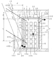
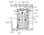
図1乃至図4は本発明の第1の実施形態に係る換気システムを示している。 1 to 4 show a ventilation system according to a first embodiment of the present invention.
本システムは、蓄熱装置付きの空気通路1と、送風手段26と、制御手段30と、入光量制御手段40とで構成されている。まず該構成のうち公知の部分について説明する。
This system includes an
空気通路1は、建物101南側のバルコニー102などに設置した、中空の箱体4で画成させた蓄熱装置2の内部と、該蓄熱装置箱体4の一部(図示例では前板5)を貫通して開口した外気導入口20と、箱体の後板6から建物外壁を貫いて空調エリア104へ開通させた連通口22とで構成されている。
The
上記蓄熱装置2は、縦長の箱体4の前板のうち下端部を除く部分を、好ましくは南向きとした透明板で形成して透光部10としている。該透光部を除く箱体内面には断熱材(図示せず)を内張りすることが望ましい。上記箱体4の左右側板8,8間には、蓄熱媒体支持材12としての棚板が上下に複数段架設され、これら各棚板上に、複数の蓄熱媒体14…を、これら蓄熱媒体14の前後に縦方向の空気流路16…を存して配置できるように設けている。もっとも蓄熱媒体支持材12は上記空気流路を確保しながら多数の蓄熱媒体14を支持できるものであればどのような構造のものでも良い。各蓄熱媒体は、黒色など日射吸収率の高い容器に蓄熱材料を封入させたものである。その蓄熱素材は、潜熱蓄熱素材とすることが望ましく、特にその融点が20〜25℃のものを用いると良い。もっとも潜熱蓄熱材以外の蓄熱材料(例えば水)を用いることも可能である。
In the
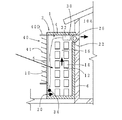
該蓄熱装置2は、冬季昼間に図1の如く上記蓄熱媒体14が受光したエネルギーの一部を送風の温度上昇に用いて残りを蓄熱し、かつ図3の如く夜間に該温熱を弱風により回収させ、又図4の如く夏季夜間の外気を大風量で吸引して蓄熱媒体14に冷熱を蓄え、夏季昼間に該冷熱を図1の如く弱風により回収するように構成している。尚、該夏季昼間には上記透光部10は後述の入光量制御手段により遮蔽されている。
The
上記外気導入口20は、上記箱体4の前板下端部に開口している。
The
上記連通口22は箱体4の後板6上端部及び建物外壁の対応部分を貫通して室内の空調領域に連通している。
The
送風手段26は、送風ファンであり、図示例では上記連通口22内に配置している。
The blower means 26 is a blower fan, and is arranged in the
制御手段30は、図示例では箱体4の頂板7上に設置された制御装置32と、上記外気導入口20に設置された第1の温度センサ34とを有し、該温度センサにより測定された外部温度に対応して上記送風手段26の送風量を制御するように構成している。更に、空調エリア104内に図示しない第2の温度センサを設置して、室内温度が下がり過ぎないように送風量の下限値を設けても良い。又、風量を手動で切替できるようにしても良い。
The control means 30 has a
本発明においては、上記透光部10からの太陽光線の入射を入光量制御手段40によって規制している。この入光量制御手段40は、季節間の太陽高度θの差を利用して太陽光線を規制するものである。
In the present invention, the incidence of sunlight from the
一般に冬至1及び夏至2における太陽高度の最大値θ1max,θ2maxは、本システムを設置する地点の緯度をα、地軸傾斜角をβ(=23.5°)とすると、次式で与えられる。
In general, the maximum solar altitudes θ 1 max and θ 2 max in
[数式1] θ1max=90°−α−β [Formula 1] θ 1 max = 90 ° −α−β
[数式2] θ2max=90°−α+β
この式によれば、太陽光の高度差は最大で地軸傾斜角の2倍(47°)もあり、この高度差を利用して、夏季に透光部への太陽光の入射を遮断しつつ、冬季の入射光量が最大となるという設計仕様を満たすように入光量制御手段を構成する。
[Formula 2] θ 2 max = 90 ° −α + β
According to this formula, the difference in altitude of sunlight is at most twice as large as the inclination angle of the earth's axis (47 °), and this difference in altitude is used to block sunlight from entering the translucent part in summer. The incident light amount control means is configured so as to satisfy the design specification that the incident light amount in winter is maximized.
本実施形態では、入光量制御手段40として、直射太陽光を遮る板状第1遮光体40Aと、間接光を生ずる照返しを防ぐ板状第2遮光体40Cとを設けている。
In the present embodiment, as the incident light amount control means 40, a plate-like first
図示の第1遮光体40Aは、上記蓄熱装置2上方の建物101外壁部分から庇状に突出する上方遮光体であり、その庇の突出長さ及び設置高さは、上記透光部10との上下巾及び位置とに対応させて上記設計仕様を満たすように決定する。
The illustrated
具体的には、図1に示す如く、上記透光部10の開口周縁のうち上縁部前端a及び下縁部後端bをそれぞれ入射角をθ1、θ2で通過する斜行直線L1及びL2を描き、これら両直線の交点cが上記上方板状遮光体40Aの前端面下縁と一致するようにすればよい。入射角θ1は冬至の最低太陽高度θ1maxより大きく、又、θ2は夏至の最高太陽高度θ2maxよりも小さく余裕を持って設計することが重要である。どの程度の余裕をとるべきかは後述する。尚、上記板状第1遮光体は、庇に限るものではなく、マンションのバルコニーなど既存建物の構造を適宜利用することができる。
Specifically, as shown in FIG. 1, an oblique line L passing through the upper edge front end a and the lower edge rear end b of the opening periphery of the
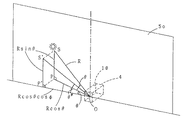
上記入射角を求めるためには、図5に示す如く南向きの透光部10へ入射する太陽光線を南北面S0へ投射したときの高度(以下実質高度という)θ*が必要となる。図5はその手順を示すものであり、三角形SPOとこれを南北面S0に投射した三角形S’P’Oとの幾何学的関係から、次式が得られる。
In order to obtain the incident angle, an altitude (hereinafter referred to as a substantial altitude) θ * when a solar ray incident on the south-facing
[数式3] θ*=tan−1(S’P’/P’O)=tan−1(tanθ/cosφ)
表1及び表2は、日中の各時刻における太陽光線の方位角φ、太陽高度θ、及びこれらから上記数式3より計算した実質高度θ*を、夏至から1月づつ離れた各日について示したものである。尚、これらの数値は東京(東経139.8、北緯35.7)について計算した理論値である。
[Formula 3] θ * = tan −1 (S′P ′ / P′O) = tan −1 (tan θ / cos φ)
Tables 1 and 2 show the azimuth angle φ, the solar altitude θ, and the real altitude θ * calculated from the
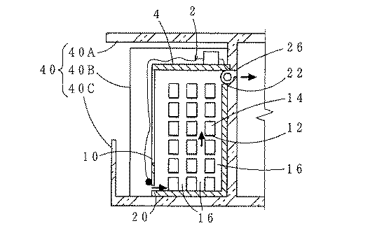
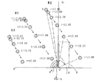
図6は、上記表1及び表2に基づいて夏至、春分、及び冬至における南中時から日没までの太陽の位置を南北面上に表したものである。この図によれば、夏至において太陽は東西面S1を横切って左から右へ移動しているから、太陽の実質高度θ*は、南中時(大凡12時)に最も小さく、その後日没に至るまで徐々に大となることが分る。日の出から南中までの間の太陽の動きは、南北面に対して面対象に表れるため、結局南中時の実質高度θ*minが一番低いこととなる。従って南中時の太陽光線が遮断するように庇の突出長を定めれば、仮にこの庇が東西に十分長いものであれば日中の太陽光を全て遮断することができる。 FIG. 6 shows the position of the sun on the north-south surface from the south midnight to the sunset in the summer solstice, the spring equinox and the winter solstice based on Tables 1 and 2 above. According to this figure, since the sun at the summer solstice is moving from the left across the east-west plane S 1 to the right, substantially highly theta * is the sun, the smallest at southing (at approximately 12), followed Sunset It turns out that it becomes large gradually until it reaches. Since the sun's movement from sunrise to south-center appears as a plane object with respect to the north-south surface, the real altitude θ * min at the time of south-center is the lowest. Therefore, if the projection length of the kite is determined so that the sun rays during the south and middle hours are blocked, if the kite is sufficiently long from east to west, all sunlight during the day can be blocked.
同様のことが春分から秋分に至る期間で生じているため、例えば四月上旬の南中時の実質高度θ*を60°とすると、図1において、θ2を60°に設定すれば四月上旬から9月中旬は日射が透光部10に全く当たらないこととなる。
The same thing occurs in the period from spring equinox to autumn equinox. For example, if the real altitude θ * at the south-central time in early April is 60 °, if θ 2 is set to 60 ° in FIG. From early to mid-September, solar radiation does not hit the
又、秋分から春分に至る期間は、一日のうち南中時の実質高度が最大である。このため、日射熱を終日取得したい期間の最高の実質高度を求めれば、これを図1のθ2に代入すれば、その期間中の全ての時間において透光部10に太陽光が入射されることとなる。例えば10月下旬から2月下旬の期間では、40°という如くである。
In addition, during the period from autumn to spring equivalency, the real altitude at the south-central time of the day is the largest. For this reason, if the highest real altitude of the period for which solar radiation heat is desired to be acquired throughout the day is determined, if this is substituted for θ 2 in FIG. 1, sunlight is incident on the
尚、実際の庇(上方遮光体)の横幅は有限なので、低高度から入射する西日や朝日を遮ることができない。そこで第1遮光手段として、上記上方遮光体40Aの他に、図1及び図2に想像線で示す如く、側方遮光体40Bを設けてもよい。該側方遮光体40Bは、上記蓄熱装置2の前側方を覆うように起立する衝立型の遮光板とすることができ、又、既存の集合住宅のバルコニーの仕切り板などで兼用することもできる。尚、周囲の環境より西日などが差さない場所では、この側方遮光体40Bを設ける必要はない。
In addition, since the actual width of the kite (upper light shield) is finite, it is not possible to block the western and rising sun incident from a low altitude. Therefore, as the first light shielding means, in addition to the upper
第2遮光体40Cは、バルコニー上面などからの照返しによる間接光を生じさせないようにするためのものである。図示例では、既述透光部10前方のバルコニー102部分上面から、手すりを兼ねた第2遮光体を起立している。該第2遮光体は、図1に示す如く冬季の透光部10への太陽光線の入射を妨げず、かつ夏季のバルコニー102上面で反射した光線をほぼ遮断するように設ける。
The second
下記の表1は、図1における透光部10前面と上方遮光体40A前端面との前後方向距離d、上方遮光体40Aの下面と上記透光部10上縁との間隙の長さg、及び透光部10の上下両縁の高低差hを、事例1から事例21まで様々に変更したときの南向き鉛直の透光部への直達日射量の測定データを示している。この表によれば透光部及び第一遮光体の設計仕様を適宜変更することで夏季の入光量を零にしながら、冬季の入光量を十分に確保できることが分る。
Table 1 below shows the distance d in the front-rear direction between the front surface of the
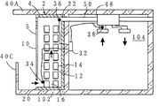
次に本実施形態の他の特徴について説明する。図2などに示す通り、既述箱体4の内部には、前方(透光部10近傍)から後方へ3列の蓄熱媒体群14A,14B,14Cを配列している。この場合に、冬季の太陽光線受光により蓄熱をするのは、主として最前列の蓄熱媒体群14Aであり、他の蓄熱媒体群14B、14Cは、主として冬季日中乃至夏季夜間の外気導入による温冷熱の蓄熱のために使用される。この場合、蓄熱媒体の表面を黒く塗装して日射吸収率を高めるなどの処理は、最前列の蓄熱媒体に対してのみ行えば良い。
Next, other features of the present embodiment will be described. As shown in FIG. 2 and the like, three rows of heat storage medium groups 14A, 14B, and 14C are arranged from the front (near the light transmitting portion 10) to the rear in the
又、このとき、最前列の蓄熱媒体列14Aの融点を20℃前後、その他の蓄熱媒体列14B,14Cの融点を25℃前後とするとよい。融点が20℃前後の蓄熱素材としてカプリン酸・ラウリン酸混合物やカプリン酸・ミリスチン酸混合物があり、又、融点が25℃前後の蓄熱素材としてカプリン酸・ステアリン酸混合物や塩化カルシウム水和塩が好適である。上記構成により、冬季昼間の太陽光入射の際には、太陽エネルギーから温熱をとって、低融点の蓄熱媒体群14Aに効率良く蓄えて該蓄熱を夜間に回収することができ、又、夏季夜間にも、外部冷気から冷熱をとって、高融点の蓄熱媒体群14B、14Cに効率良く蓄えることができる。 At this time, the melting point of the first heat storage medium row 14A may be about 20 ° C., and the melting points of the other heat storage medium rows 14B and 14C may be about 25 ° C. Capric acid / lauric acid mixture and capric acid / myristic acid mixture are available as heat storage materials with a melting point of around 20 ° C, and capric acid / stearic acid mixture and calcium chloride hydrate are preferred as heat storage materials with a melting point of around 25 ° C. It is. With the above configuration, when sunlight is incident during winter daytime, it is possible to take heat from solar energy, efficiently store it in the low melting point heat storage medium group 14A, and recover the heat storage at night. In addition, cold heat can be taken from the external cold air and efficiently stored in the high-melting-point heat storage medium groups 14B and 14C.
以下、本発明の他の実施形態を説明するが、該構成のうち第1実施形態と同一の事項については同一符号を付することで説明を省略する。 Hereinafter, although other embodiment of this invention is described, the description is abbreviate | omitted by attaching | subjecting the same code | symbol about the matter same as 1st Embodiment among this structure.
図7及び図9は、本発明の第2の実施形態を示している。 7 and 9 show a second embodiment of the present invention.
本実施形態は、既述入光量制御手段40として、上記蓄熱装置2の透光部10に、複数の羽根板41からなるルーバー40Dを設けたものである。それら羽根板の角度は手動により調整可能とすることが望ましい。これについては、後述する。
In the present embodiment, a
上記羽根板41の傾斜角度及び巾は次のように設計する。羽根板41の傾斜角度は、冬季のある期間の太陽高度の平均値θとすればよく、これにより当該期間における羽根板41による影面積の合計を最小として入射光量を最大とすることができる。例えば10月下旬から2月下旬の9時〜15時であれば、30°程度という如くである。この数値は冬至における太陽の南中高度とほぼ同じである。尚、冬至におけるに日射量を多くするため、例えば羽根板41の角度を27°程度とすることもできる。又、各羽根板の間隔と長さは、ある羽根板F1の後端部01と隣接する上方羽根板F2の先端部Nとを通る光線の角度θ2について、前述の庇の場合と同様に決定すればよい。
The inclination angle and width of the
次の表4は、既述表3と同様にルーバの図8における各寸法を様々に変更した場合の日射量を示したデータである。これらのなかでは例えば事例8(θ1=27°、θ2=56°)などの設定が夏季の遮光及び冬季の透光の各機能が明瞭で好適である。 The following Table 4 is data showing the amount of solar radiation when the dimensions of the louver in FIG. Among these, for example, setting of example 8 (θ 1 = 27 °, θ 2 = 56 °) is clear and suitable for each function of light shielding in summer and light transmission in winter.
尚、既述庇状の遮光体に比べてルーバーの場合には羽根板の角度等を設定してもある程度の影ができるため、冬季の日射量を最大とするためには手動乃至自動で羽根板の傾斜角度を調整することが望ましい。既述表2によれば、12月22日(冬至)における午前9時から12時迄の間の実質高度は24.7〜30.8°、11月22日では28.8〜34.3°、10月22日では40.3〜43.5°であり、それぞれの各平均値は約28°、32°、42°であってそれぞれにかなりの差がある。そこで例えば12月、11・1月、10・2月のそれぞれの日射角度の平均値に、羽根板の傾斜角度を月に一度調整すれば良い。 In the case of a louver, a certain amount of shadow can be produced in the case of a louver as compared with the above-described saddle-shaped light-shielding body. Therefore, in order to maximize the amount of solar radiation in winter, the blades can be manually or automatically It is desirable to adjust the inclination angle of the plate. According to Table 2 above, the actual altitude between 9:00 am and 12:00 am on December 22 (winter solstice) is 24.7-30.8 degrees, 28.8-34.3 degrees on November 22, and 40.3 on October 22. It is ˜43.5 °, and each average value is about 28 °, 32 °, and 42 °, and there is a considerable difference between them. Therefore, for example, the inclination angle of the blades may be adjusted once a month to the average value of the solar radiation angles in December, November, January, and October.
図9は、第2実施形態の変形例であって、上述の各月毎の好ましい羽根板41の傾斜角の目盛り43aを示す目盛り板43の構成を示している。この目盛り板は例えばルーバー40Dの羽根板41端面に沿って吊下げるように構成しており、目盛りに沿って羽根板の角度を手動で調整できるようにしている。尚、図示例では、該目盛り板は、側外方より透視して目盛りと羽根板とを角度合わせ可能な透明板としているが、必ずしもこのような構造にする必要はない。又図示例と異なり、自動で羽根板の角度調節をする場合には、例えば月毎の好ましい羽根板41の傾斜角度を記憶した制御装置及び該制御装置からの指令に従って羽根板41の角度を変える角度調整装置を、図7及び図8の構成に加えれば良い。尚、上記は日射取得熱量を最大にする方法であるが、地域によっては暖房負荷の大きくない10月、11月などはむしろルーバーの角度調整によって日射を遮ってもよい。
FIG. 9 is a modified example of the second embodiment, and shows a configuration of the
図10は、本発明の第3の実施形態を示している。この実施形態は、箱体4の底板及び天板からそれぞれ流路形成用の仕切り板44…を互い違いにかつ既述複数列(図示例では3列)の蓄熱媒体14A、14B…の間に突出したものであり、これにより箱体4内部に蛇行流路に沿って蓄熱媒体を配置することができ、蓄熱を効率良く回収することができる。
FIG. 10 shows a third embodiment of the present invention. In this embodiment, the
図11は、本発明の第4の実施形態を示している。この実施形態は、第3実施形態における仕切り板44に代えて、補助送風手段46としての送風ファンを箱体4の頂板下面中央に設置したものである。該構成によれば、冬季の日中に外気導入口20から箱体4内へ入った外気は、最前列の蓄熱媒体群14Aへの日射によって暖められて上昇するが、この空気を上記送風ファンが攪拌し、蓄熱媒体群14B、14Cに対しても十分な蓄熱を行ったあと外部へ排出される。
FIG. 11 shows a fourth embodiment of the present invention. In this embodiment, instead of the
図12は、本発明の第5の実施形態を示している。本実施形態は、既述の換気システムの構成と全熱交換器48とを設けたものである。本実施形態では、箱体4の連通口22から建物101を貫いて外方へ開口する送風ダクト50を設けるとともに、空調エリア104を通る送風ダクト部分の一部に全熱交換器48を設け、箱体4の外気導入口20と連通口22と空調エリア104とにそれぞれ第1、第2、第3温度センサ34,36,38を設置し、これらセンサで測定した温度と設定温度とから、制御装置32が全熱交換器のオンオフ切替を可能に構成したものである。
FIG. 12 shows a fifth embodiment of the present invention. In the present embodiment, the configuration of the ventilation system described above and the
1…空気通路 2…蓄熱装置 4…箱体 5…前板 6…後板 7…頂板
8…左右側板 10…透光部 12…蓄熱媒体支持材 14…蓄熱媒体
14A,14B,14C…蓄熱媒体群 16…空気流路
20…外気導入口 22…連通口 26…送風手段
30…制御手段 32…制御装置 34…第1温度センサ 36…第2温度センサ
38…第3温度センサ
40…入光量制御手段 40A,40B…板状第1遮光体 40C…板状第2遮光体
40D…ルーバー 41…羽根板 43…目盛り板 43a…目盛り 44…仕切り板
46…補助送風手段 48…全熱交換器 50…ダクト
101…建物 102…バルコニー 103…外壁 104…空調エリア
a…透光部上縁部分前端 b…透光部下縁部分後端 c…交点
DESCRIPTION OF
8 ... Left and
14A, 14B, 14C ... heat
20 ...
30 ... Control means 32 ...
38 ... Third temperature sensor
40 ... Incident light intensity control means 40A, 40B ... Plate-shaped first
40D ...
46 ... Auxiliary ventilation means 48 ... Total heat exchanger 50 ... Duct
101 ... Building 102 ... Balcony 103 ...
Claims (9)
Temperature sensors 34, 36, and 38 are installed at the outside air inlet 20, the communication port 22, and the air conditioning area 104, respectively, and the total heat installed in the air conditioning area 104 is determined from the measured temperature by these sensors and the set temperature of the air conditioning area. The regenerative ventilation system according to any one of claims 2 to 8, wherein the on / off switching of the exchanger 48 and the air flow rate are controlled.
Priority Applications (1)
| Application Number | Priority Date | Filing Date | Title |
|---|---|---|---|
| JP2004097219A JP2005282942A (en) | 2004-03-29 | 2004-03-29 | Heat storage type ventilation system |
Applications Claiming Priority (1)
| Application Number | Priority Date | Filing Date | Title |
|---|---|---|---|
| JP2004097219A JP2005282942A (en) | 2004-03-29 | 2004-03-29 | Heat storage type ventilation system |
Publications (1)
| Publication Number | Publication Date |
|---|---|
| JP2005282942A true JP2005282942A (en) | 2005-10-13 |
Family
ID=35181537
Family Applications (1)
| Application Number | Title | Priority Date | Filing Date |
|---|---|---|---|
| JP2004097219A Pending JP2005282942A (en) | 2004-03-29 | 2004-03-29 | Heat storage type ventilation system |
Country Status (1)
| Country | Link |
|---|---|
| JP (1) | JP2005282942A (en) |
Cited By (9)
| Publication number | Priority date | Publication date | Assignee | Title |
|---|---|---|---|---|
| JP2009063200A (en) * | 2007-09-05 | 2009-03-26 | Shiraiwa Komusho:Kk | Building air conditioning system |
| JP2012019090A (en) * | 2010-07-08 | 2012-01-26 | Sanken Electric Co Ltd | Heat absorbing device |
| JP2012023295A (en) * | 2010-07-16 | 2012-02-02 | Sanken Electric Co Ltd | Heat absorption structure for outdoor device |
| JP2013213394A (en) * | 2012-03-09 | 2013-10-17 | Asahi Kasei Homes Co | Louver device |
| JP2014181864A (en) * | 2013-03-19 | 2014-09-29 | Okaya Koki Kk | Heat storage device |
| JP2016166692A (en) * | 2015-03-09 | 2016-09-15 | 株式会社ドリームエナジー | Heat storage heating device |
| JP2018185119A (en) * | 2017-04-27 | 2018-11-22 | 三協立山株式会社 | Heat storage building material, and cold storage building material |
| CN113280433A (en) * | 2021-05-17 | 2021-08-20 | 东北石油大学 | Ventilating duct containing nano-particle paraffin capable of realizing bidirectional ventilation |
| CN116951549A (en) * | 2022-04-13 | 2023-10-27 | 珠海格力电器股份有限公司 | Patio machine with heating mode |
-
2004
- 2004-03-29 JP JP2004097219A patent/JP2005282942A/en active Pending
Cited By (11)
| Publication number | Priority date | Publication date | Assignee | Title |
|---|---|---|---|---|
| JP2009063200A (en) * | 2007-09-05 | 2009-03-26 | Shiraiwa Komusho:Kk | Building air conditioning system |
| JP2012019090A (en) * | 2010-07-08 | 2012-01-26 | Sanken Electric Co Ltd | Heat absorbing device |
| JP2012023295A (en) * | 2010-07-16 | 2012-02-02 | Sanken Electric Co Ltd | Heat absorption structure for outdoor device |
| JP2013213394A (en) * | 2012-03-09 | 2013-10-17 | Asahi Kasei Homes Co | Louver device |
| JP2014181864A (en) * | 2013-03-19 | 2014-09-29 | Okaya Koki Kk | Heat storage device |
| JP2016166692A (en) * | 2015-03-09 | 2016-09-15 | 株式会社ドリームエナジー | Heat storage heating device |
| JP2018185119A (en) * | 2017-04-27 | 2018-11-22 | 三協立山株式会社 | Heat storage building material, and cold storage building material |
| JP7161841B2 (en) | 2017-04-27 | 2022-10-27 | 三協立山株式会社 | Heat storage building materials, cold storage building materials |
| CN113280433A (en) * | 2021-05-17 | 2021-08-20 | 东北石油大学 | Ventilating duct containing nano-particle paraffin capable of realizing bidirectional ventilation |
| CN113280433B (en) * | 2021-05-17 | 2022-05-17 | 东北石油大学 | Ventilating duct containing nano-particle paraffin capable of realizing bidirectional ventilation |
| CN116951549A (en) * | 2022-04-13 | 2023-10-27 | 珠海格力电器股份有限公司 | Patio machine with heating mode |
Similar Documents
| Publication | Publication Date | Title |
|---|---|---|
| Watson | Bioclimatic design | |
| ES2575020T3 (en) | Greenhouse and system to generate electricity and cultivation in greenhouses | |
| US4119084A (en) | Building with passive solar energy conditioning | |
| Freewan | Advances in Passive Cooling Design: An Integrated Design | |
| WO2012119604A1 (en) | A window shutter unit for external mounting on a building | |
| Maleki | Shading: Passive cooling and energy conservation in buildings | |
| Bliss | The performance of an experimental system using solar energy for heating and night radiation for cooling a building | |
| JP2011177107A (en) | Heat shielding/insulating window apparatus for sunlight-combined type plant factory | |
| JP2011125276A (en) | Automatic sunshine system in solid garden laid on multiple-layer building | |
| Nikolic et al. | Basic principles of passive solar heating | |
| Hlaing et al. | Comparative Study on Performance of Wind-Catcher Shading Device and Other Types of Shading Device on Residential Houses in Tropics. | |
| Nwaigwe et al. | Review of nocturnal cooling systems | |
| CN102080432A (en) | Outside-sunshade and solar-tracking parabolic-reflector solar thermal collector integrated with building | |
| Savero et al. | Review on design strategies of energy saving office building with evaporative cooling in tropical region | |
| Steemers | Environmental issues of building design | |
| JP2006028773A (en) | Slat angle control device for electric blind | |
| Ahamed | Thermal environment modeling and optimization of greenhouse in cold regions | |
| Giyasov et al. | Innovative facade systems for buildings in hot climate conditions | |
| JP2011179225A (en) | Blind for changing optical incidence angle | |
| Jayasinghe et al. | Passive techniques for residential buildings in low altitudes of Sri Lanka | |
| Onazi et al. | An appraisal of shading devices in institutional buildings | |
| JPH06248857A (en) | blind | |
| Steemers | The state of the art in passive cooling | |
| Babota | Increase energy efficiency and comfort in homes by incorporating passive solar design features | |
| Abdussalam et al. | Effect of passive cooling on the indoor thermal quality of an institutional building in tropical savannah climate |
Legal Events
| Date | Code | Title | Description |
|---|---|---|---|
| A621 | Written request for application examination |
Free format text: JAPANESE INTERMEDIATE CODE: A621 Effective date: 20061227 |
|
| A977 | Report on retrieval |
Free format text: JAPANESE INTERMEDIATE CODE: A971007 Effective date: 20090722 |
|
| A131 | Notification of reasons for refusal |
Free format text: JAPANESE INTERMEDIATE CODE: A131 Effective date: 20090729 |
|
| A02 | Decision of refusal |
Free format text: JAPANESE INTERMEDIATE CODE: A02 Effective date: 20091125 |