JP2005285387A - Electronic switch breaker with magnetic structure - Google Patents
Electronic switch breaker with magnetic structure Download PDFInfo
- Publication number
- JP2005285387A JP2005285387A JP2004094069A JP2004094069A JP2005285387A JP 2005285387 A JP2005285387 A JP 2005285387A JP 2004094069 A JP2004094069 A JP 2004094069A JP 2004094069 A JP2004094069 A JP 2004094069A JP 2005285387 A JP2005285387 A JP 2005285387A
- Authority
- JP
- Japan
- Prior art keywords
- breaker
- movable
- iron core
- permanent magnet
- magnetic structure
- Prior art date
- Legal status (The legal status is an assumption and is not a legal conclusion. Google has not performed a legal analysis and makes no representation as to the accuracy of the status listed.)
- Pending
Links
- XEEYBQQBJWHFJM-UHFFFAOYSA-N Iron Chemical group [Fe] XEEYBQQBJWHFJM-UHFFFAOYSA-N 0.000 claims abstract description 51
- BQCADISMDOOEFD-UHFFFAOYSA-N Silver Chemical compound [Ag] BQCADISMDOOEFD-UHFFFAOYSA-N 0.000 claims abstract description 33
- 229910052709 silver Inorganic materials 0.000 claims abstract description 33
- 239000004332 silver Substances 0.000 claims abstract description 33
- RYGMFSIKBFXOCR-UHFFFAOYSA-N Copper Chemical compound [Cu] RYGMFSIKBFXOCR-UHFFFAOYSA-N 0.000 claims abstract description 29
- 229910052802 copper Inorganic materials 0.000 claims abstract description 28
- 239000010949 copper Substances 0.000 claims abstract description 28
- 239000004020 conductor Substances 0.000 claims description 13
- 230000003321 amplification Effects 0.000 claims description 10
- 238000003199 nucleic acid amplification method Methods 0.000 claims description 10
- 210000003298 dental enamel Anatomy 0.000 claims description 5
- 229910052742 iron Inorganic materials 0.000 claims description 5
- 238000005070 sampling Methods 0.000 claims description 4
- 238000007493 shaping process Methods 0.000 claims description 4
- 230000003068 static effect Effects 0.000 abstract description 4
- 230000000903 blocking effect Effects 0.000 abstract 1
- 238000011084 recovery Methods 0.000 description 5
- 230000009471 action Effects 0.000 description 4
- 230000005611 electricity Effects 0.000 description 3
- 230000005389 magnetism Effects 0.000 description 2
- 238000004519 manufacturing process Methods 0.000 description 2
- 230000005856 abnormality Effects 0.000 description 1
- 238000004378 air conditioning Methods 0.000 description 1
- 239000000956 alloy Substances 0.000 description 1
- 238000013459 approach Methods 0.000 description 1
- 230000005540 biological transmission Effects 0.000 description 1
- YCKOAAUKSGOOJH-UHFFFAOYSA-N copper silver Chemical compound [Cu].[Ag].[Ag] YCKOAAUKSGOOJH-UHFFFAOYSA-N 0.000 description 1
- 238000005265 energy consumption Methods 0.000 description 1
- 238000001914 filtration Methods 0.000 description 1
- 238000012423 maintenance Methods 0.000 description 1
- 230000008439 repair process Effects 0.000 description 1
- 230000004044 response Effects 0.000 description 1
Images

Landscapes
- Emergency Protection Circuit Devices (AREA)
- Breakers (AREA)
Abstract
Description
本発明は磁力構造を具有する電子式スイッチブレーカに係り、特に磁力構造及び電流調整機能を具有し、且つショート状態をロックできるものであり、且つ電話機及び音声システムとキーボード、並びにソフトプログラムなどを組み合わせることにより、電話によるリモートコントロールシステムと合わせて使用できる電子式スイッチブレーカに関わる。 The present invention relates to an electronic switch breaker having a magnetic structure, in particular, having a magnetic structure and a current adjustment function, and capable of locking a short-circuit state, and combining a telephone, a voice system, a keyboard, a software program, and the like. In particular, the present invention relates to an electronic switch breaker that can be used with a remote control system by telephone.
公知のブレーカは、主に機械構造を採用しており、レバーや伝動構造、感熱磁力解放構造などで回路に過負荷やショート、漏電などの故障が生じた際に自動的に電源を断ち、電器の使用における安全を確保するものである。
しかし上述のような設計では、機械構造がブレーカ内を占めるスペースが大きく、ブレーカの体積が相対して大きくなりコストも高くつくこと、並びに機械構造本体における欠点としては安定性に欠け故障しやすいことが言える。こういったブレーカが故障すれば使用者がこれを正常に働くよう再度設定しなければならず、またリモコン操作ができない不便さもある。
またショートが生じて故障した後にも、ロック機能がないことからブレーカが故障しても電流が投入され、電流が大きくなると共にアークが大きくなるため二次的損傷が生じて使用者は危険にさらされることになる。
過負荷電流に対する保護はバイメタル片や磁性油管によって保護部としているが、該バイメタル片は合金材質によるものであり、通電時には熱量を生じるためエネルギーの消耗と破損を免れられず、また自然の環境下では温度に対して敏感であり、温度差が大きいときに異常を来たしやすいといった問題もある。また磁性油管は、その精確さと過負荷電流において調整がきかないこと、また製造工程が複雑且つ製造時の誤差が大きいなどの欠点もある。
そこで上述の欠点に鑑み、使用上の安全を強化すると同時にリモコン操作を実現して実用性を高めるべく、本発明の磁力構造を具有する電子式スイッチブレーカを提供する。
However, in the design as described above, the space that the machine structure occupies in the breaker is large, the volume of the breaker is relatively large and the cost is high, and the disadvantage of the machine structure body is that it lacks stability and is prone to failure. I can say. If such a breaker breaks down, the user must set it again to work normally, and there is also the inconvenience that the remote control cannot be operated.
In addition, even after a failure due to a short circuit, there is no lock function, so even if the breaker fails, a current is applied and the current increases and the arc becomes larger, causing secondary damage and putting the user at risk. Will be.
Protection against overload current is protected by a bimetal piece or magnetic oil pipe, but the bimetal piece is made of an alloy material and generates heat when energized, so energy consumption and damage cannot be avoided. However, there is also a problem that it is sensitive to temperature and is likely to cause abnormality when the temperature difference is large. Magnetic oil pipes also have drawbacks such as inaccuracy and overload current adjustment, complicated manufacturing processes, and large manufacturing errors.
Accordingly, in view of the above-described drawbacks, an electronic switch breaker having the magnetic structure of the present invention is provided in order to enhance safety in use and at the same time realize remote control operation and enhance practicality.
ブレーカの構造にはボタン式スイッチ或いはスイッチレバーの中間に設けた可動軸上の可動銅片と動銀接点を、外殻内の対応する位置上の左固定銅及び右固定銅上の静止銀接点と相対させて設け、該左固定銅と右固定銅の間には磁力構造を設け、該磁力構造中間には永久磁石を設け、該永久磁石の両側は二つの鉄心板を設け、一方の該鉄心板上にはコイル架を設け、該コイル架にはエナメル線を巻設し、該エナメル線をCPUと連結させ、もう一方の該鉄心板上にはメイン回路導線を巻設し、可動銅片下方にも純鉄を設け、静止磁石とCTを出入力端のメイン回路上にて直列状態で設け、該静止磁石上方は可動磁石を設け、レバーの一端を可動磁石可動回路上に位置させ、該レバーのもう一端を嵌合部と連結させ、該嵌合部の一端にはバネを連結させ、該嵌合部のもう一端を可動軸と接触させ、更に解放器と電流調整ブロックを設け、該CTシグナルが電子回路の整形増幅、サンプリング調整、前置増幅、動力増幅を経て該解放器にまで至らしめ、該CTと電子回路板を一つの外殻内に納めると共に、更に電話機や音声システムとキーボード、並びにソフトプログラムなどで電話によるリモートコントロールシステムを構成し、該音声システムと電話によるリモコン部分で処理されたシグナルを該ブレーカ中のCPU回路にまで伝送し、該CPU回路板が該ブレーカのコイルにまでアウトプットし、また該ブレーカの入力端を住宅などの一般の電気と接続し、出力端を電器に接続する。
The breaker structure consists of a movable copper piece on a movable shaft and a moving silver contact in the middle of a button switch or switch lever, and a stationary silver contact on the left fixed copper and right fixed copper on the corresponding position in the outer shell. A magnetic structure is provided between the left fixed copper and the right fixed copper, a permanent magnet is provided in the middle of the magnetic structure, two iron core plates are provided on both sides of the permanent magnet, A coil rack is provided on the iron core plate, an enamel wire is wound around the coil rack, the enamel wire is connected to the CPU, a main circuit conductor is wound on the other iron core plate, and the movable copper Pure iron is also provided below one side, a stationary magnet and CT are arranged in series on the main circuit at the input / output end, a movable magnet is provided above the stationary magnet, and one end of the lever is positioned on the movable magnet moving circuit. The other end of the lever is connected to the fitting part, and a spring is connected to one end of the fitting part. The other end of the fitting portion is brought into contact with the movable shaft, and further, a releaser and a current adjustment block are provided, and the CT signal passes through shaping amplification, sampling adjustment, preamplification, and power amplification of the electronic circuit to the releaser. The CT and the electronic circuit board are housed in one outer shell, and the telephone, voice system and keyboard, and a remote control system by telephone is configured by a software program, etc., and the remote control part by the voice system and telephone The signal processed in
本発明によると、体積が小さく構造が簡単、且つ低コストでメンテナンスも容易等、多くの利点を提供すると同時に、電話機を合わせてリモコン操作機能を兼ね備えた実用性の高いブレーカを提供することに成功した。 According to the present invention, it offers many advantages such as small volume, simple structure, low cost and easy maintenance, and at the same time, it has succeeded in providing a highly practical breaker that combines a remote control function with a telephone. did.
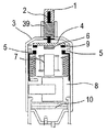
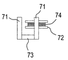
図1,2に示すように、本発明は外殻3を具有し、該外殻3上には手動ボタン1(又はスイッチレバー)が設けられており、該手動ボタン1中間は可動軸2であり、該可動軸2上には回復バネ39が設けられており、該可動軸2下端は該外殻3内に位置して可動銅片4と結合しており、該可動銅片4下側面の中段個所には可動鉄心ブロック6が連接している。該外殻3内には該可動銅片4の下側面両端に設けた可動銀接点9に対応する静止銀接点5が設けられており、該静止銀接点5はそれぞれ軟銅線8によって商用電源と接続される。また該外殻3内の中間位置には磁力構造7が設けられており、該磁力構造7とは鉄心版71とコイル架72及び永久磁石73とコイル74とより構成され、該二つの鉄心板71は純鉄とする。該二つの鉄心板71の間は永久磁石73が設けられ、二つあるうち任意の鉄心板71上段にはコイル架72が設けられて該鉄心板71に巻設されており、該コイル架72上にはエナメル線74が巻回されており、該コイル74回路の開閉はCPU回路板10のコントロールを受けるものとする。
As shown in FIGS. 1 and 2, the present invention has an
該コイル74が通電する前は該永久磁石73が該可動銅片4上の可動鉄心ブロック6を引き付けられない状態であり、該可動軸2は動かず、該手動ボタン1は下降位置にないため該可動銅片4上の可動銀接点9とこれに対応する静止銀接点5とが接触せず非通電状態であることからブレーカは未だ作動せず、通電状態にない。該コイル74の回路がCPUの指令を受けて閉とされ、正の極性で導通すると、該鉄心板71が磁力を生じて該可動銅片4上の可動鉄心ブロック6を吸引し、該可動軸2が該手動ボタン1上のバネに抗して下降し、該可動銀接点9と該静止銀接点5とが接触し、商用電源から通電されてブレーカが作動する通電状態となる。
該ブレーカが作動状態に入った後、CPUからの指令で該コイル74の回路が開となって該コイル74が非通電状態となり、該鉄心版71が磁力を失って該可動鉄心ブロック6を吸引できなくなるが、該可動鉄心ブロック6が下降位置で該永久磁石73に接近にしているため、該永久磁石73の磁力により該可動鉄心ブロック6が吸引されて該静止銀接点5は通電状態にあり、ブレーカは引き続き作動状態が保たれる。
過負荷やショート、或いは漏電、損傷などの故障が検知されるとCPUより指令が発せられ、該コイル74回路が通電状態となるが、この場合は元の極性とは逆極性で通電されるため、該鉄心板71は上記とは逆の磁性を生じ、該永久磁石73の該可動鉄心ブロック6に対する磁力が打ち消されて該可動鉄心ブロック6が引き付けられず、回復バネの反発力の作用で、該可動軸2上の該可動銅片4とその上の鉄心ブロック6が上向きに反撥され、該可動銀接点9と該静止銀接点5が離れ、電流が遮断された状態となり、ブレーカが非作動状態となる。修理等により正常な状態に戻ると、ブレーカが引き続き作動状態に入って上述の動作が繰り返される。
Before the
After the breaker enters the operating state, the circuit of the
When a fault such as overload, short circuit, electric leakage, or damage is detected, the CPU issues a command and the
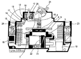
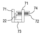
図3,4に示すように、本発明の構造では、該ブレーカが落ちた状態では該可動銅片4は上方に位置し、両端の該可動銀接点9と静止銀接点5とは離れた状態にあり、よって入力端24は銅導線22と静止銀接点5と可動銀接点9とメイン回路導線16を経て出力端23に至る回路が断たれた状態となってブレーカが非作動状態となる。
該ブレーカが正常に働いているときは、該ロックバー17は下降した位置にあり、該ロックバー17上の欠け口20が嵌合部12の位置に至り、該嵌合部12はバネ13の作用によって該欠け口20に嵌入し、該嵌合部12とレバー11の一端が係合する。該レバー11には回転軸点(ブレーカ上)があり、よって該レバー11の他端が計回りに回転して、可動磁石14を図3の破線の位置に押し上げ、該可動磁石14と静止磁石15とが離れている。
この状態で該スイッチ本体19はばねの反発力に抗して下降位置にあって該可動銅片4はその両端の該可動銀接点9と下面の静止銀接点5とを接触させることで、該入力端24と銅導線22と静止銀接点5と可動銀接点9とメイン開度導線16が該出力端23のメイン回路を通電させてブレーカを作動状態に至らせている。
このとき、該磁力構造7中の永久磁石が該可動鉄心ブロック6を吸引し、該静止銀接点を通電状態にし、該銅導線22は該鉄心板上のブレーカが正常に働いているときに一定の磁力を生じるが、設定された銅導線22の数値をクリアする範囲内であるため、このように正常に働いている際の電流による磁力の作用は考慮に入れなくともよい。該メイン回路導線16で生じる磁力も該可動磁石14に対して作用しない。
該メイン回路中でショートが生じると、全体の回路に極めて大きな電流が流れ、該銅導線22と該鉄心板が該永久磁石73と該可動鉄心ブロック6との間で巨大な磁力を生じ、ショートによる逆極性の磁力が該永久磁石73が該可動鉄心ブロック6を吸引する磁力を打ち消し、該スイッチ本体19が回復バネの作用で上向きに押し上げられ、該静止銀接点が離れてメイン回路が断たれた状態となりブレーカが作動しない状態となる。
ショートの際には同時に該メイン回路導線16が大きな磁力を生じ、該可動磁石14と静止磁石15とが吸引しあって該レバー11を反時計回りに回転させ、該レバー11のもう一端に連接する嵌合部12が該ロックバー17を該欠け口20から離れ、該ロックバー17が該引張バネ18の作用により上向きに跳ね上がる。
As shown in FIGS. 3 and 4, in the structure of the present invention, when the breaker is dropped, the
When the breaker is operating normally, the
In this state, the switch body 19 is in the lowered position against the repulsive force of the spring, and the
At this time, the permanent magnet in the
When a short circuit occurs in the main circuit, a very large current flows through the entire circuit, and the
At the same time, when the short circuit occurs, the
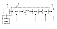
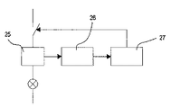
図5,6に示すように、CTは電流感知部25となり、感知されたシグナルを電子回路26に入力し、前置増幅、整形増幅、動力増幅、並びにサンプリング調整を経て更に解放器27にまでアウトプットし、該電流感知部25がアウトプットする整流濾波がそれぞれ上述の該電子回路26の各部分に至る。
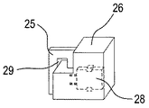
図7に示すように、該電子回路26の回路板と電流感知部25とは一つの外殻内に納められており、電流調整ブロック28によって感知された過負荷電流数値を調整する。
正常に働いているときは電流は過負荷となることなく、電流が過負荷となったときは該電流感知部25はメイン回路線穿孔29の電線中から過負荷電流を感知し、シグナルが該電子回路26に送られて前置増幅、整形増幅、動力増幅、並びにサンプリング調整を経て更に解放器27にまでアウトプットされ、該解放器27は遮断回路中の電流を解放して電器を破損するに至らせないよう保護する。
As shown in FIGS. 5 and 6, the CT becomes a
As shown in FIG. 7, the circuit board of the
When working normally, the current is not overloaded. When the current is overloaded, the
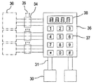
また実施例としては図3,8,9,10に示すように、ブレーカ34と電話機30の入力線31及び音声システムとキーボード37及び電話コントロールモジュール33及びディスプレイモニタ38などより構成される電話を利用したリモートコントロールシステムを設け、該システムによって電器36をコントロールするものであるが、該電話機30の電話入力線31を電話コントロールモジュール33及び音声システムとキーボード37及びディスプレイモニタ38に接続し、アウトプットは該ブレーカ34中のCPU回路板10と接続し、該CPU回路板10がエナメル線74を制御し、該磁力構造ブレーカのインプットは一般の住宅などにおける電器35と接続し、アウトプットを電器36と接続する(末端は図中の破線参照)。
As an embodiment, as shown in FIGS. 3, 8, 9, and 10, a telephone comprising a
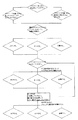
電話がかかってくると、図8に示すように該電器36をリモコン操作しようとする場合では、先ずパスワードを入力し、順を追ってプログラムを処理してゆくが、電器をオンにしようとする場合、音声システムと電話コントロールモジュール33がシグナルをブレーカ34中のCPU回路板10にまでアウトプットする。該CPU回路板10は該エナメル線74を通電状態にし、該可動鉄心ブロック6を吸引し、両端の可動銀接点9と下面の静止銀接点5とを相互に接触させ、該入力端24と純鉄22及び静止銀接点25と銅銀接点9並びにメイン回路導線16を該出力端23のメイン回路にまで通電させ、該ブレーカがコントロールする電器をオンの状態にし、該ブレーカが通電状態になると該ブレーカ中のCPU回路板10が再び指令を発し、該エナメル線74の回路を断ち、該エナメル線74が非通電状態となる。従って該鉄心ブロック71が磁性を失い、該可動鉄心ブロック6を吸引できない状態となり、該可動鉄心ブロック6が下がって該永久磁石73と接近し、該永久磁石73が該可動鉄心ブロック6を吸引する。また電器をオフにしようとする際には、同様にしてソフトプログラムの処理を行い、該音声システムと電話コントロールモジュール33でシグナルを該ブレーカ34中のCPU回路板10にまでアウトプットし、該CPU回路板10が該コイル74回路を通電状態にするが、元は正方向であったのとは逆向きの負方向の電源が入ってくるため、該鉄心板71は元と逆の磁性が生じ、該永久磁石73の該可動鉄心ブロック6に対する磁力が打ち消され、該可動鉄心ブロック6が吸引されず、回復バネの弾力によって該可動軸2が該可動銅片4及びそのお植えの該可動鉄心ブロック6を上向きに跳ね上げ、該可動銀接点9と該静止銀接点5が離れ、該ブレーカが作動しない状態に入り電器がオフの状態となる。
When a telephone call is received, if the
具体的には空調設備やボイラー、盗難防止機能を具有するドア、或いはペットに自動的に餌を与える装置等、更に多くの電器36をコントロールしようとする場合等、それらに相対するブレーカ34を増設するだけでよい。
また図10に示すように、コントロール装置32を形成する場合は、入力端を住宅の電源と直接接続し、出力端を該電源36に接続し、更に該電話入力線31を電話回路に挿設することでコントロールする目的を達成させる。
Specifically, if you want to control more
As shown in FIG. 10, when the
1 ボタン
10 CPU回路板
11 レバー
12 嵌合部
13 バネ
14 可動磁石
15 静止磁石
16 メイン回路導線
17 ロックバー
18 引張バネ
19 スイッチ本体
2 可動軸
20 欠け口
21 グリップ
22 銅導線
23 出力端
24 入力端
25 電流感知部
26 電子回路
27 解放器
28 電流調整ブロック
29 線穿孔
3 外殻
30 電話機
31 電話入力線
32 コントローラ
33 電話コントロールモジュール
34 ブレーカ
35 一般の住宅用電気
36 電器
37 音声システムとキーボード
38 ディスプレイモニタ
39 回復ばね
4 可動銅片
5 静止銀接点
6 可動鉄心ブロック
7 磁力構造
71 鉄心板
72 コイル架
73 永久磁石
74 エナメル線(磁性コイル)
8 軟銅線
9 可動銀接点
DESCRIPTION OF
8
Claims (4)
手動ボタン或いはスイッチレバー中間の可動軸上の可動銅片に設けた可動銀接点と外殻内左右固定銅片上の静止銀接点とが相対して設けられており、該左右固定銅片の間には磁力構造が設けられており、該磁力構造中央には永久磁石が設けられており、該永久磁石両側は二つの鉄心板であり、該鉄心板のうちの一つにはコイル架が設けられており、該コイル架にはエナメル線が巻回されており、該エナメル線はCPUと接続し、もう一つの該鉄心板上にはメイン回路導線が巻回されており、更に該可動銅片下方には純鉄が設けられており、静止磁石がCTと出入力端のメイン回路上にて直列しており、該静止磁石上方は可動磁石であり、ショートロック構造のレバー一端が該可動磁石の可動回路上に位置し、該レバーのもう一端は嵌合部と連結されており、該嵌合部の一端にはバネが連接しており、もう一端は該可動軸と接触していることを特徴とする磁力構造を具有する電子式スイッチブレーカ。 A breaker having a magnetic actuation mechanism,
A movable silver contact provided on the movable copper piece on the movable shaft in the middle of the manual button or switch lever and a stationary silver contact on the left and right fixed copper piece in the outer shell are provided relative to each other, and between the left and right fixed copper pieces. Has a magnetic structure, a permanent magnet is provided at the center of the magnetic structure, two iron core plates are provided on both sides of the permanent magnet, and a coil rack is provided on one of the iron core plates. An enameled wire is wound around the coil rack, the enameled wire is connected to the CPU, a main circuit conductor is wound on another iron core plate, and the movable copper piece Pure iron is provided below, a stationary magnet is connected in series with the main circuit of CT and the input / output end, the stationary magnet is above the movable magnet, and one end of the lever of the short lock structure is the movable magnet The other end of the lever is connected to the fitting part. Cage, to one end of the fitting portion and the spring is connected, the electronic switch breaker other end to androgynous magnetic force structure, characterized in that in contact with the movable shaft.
該CTシグナルは電子回路の整形増幅、サンプリング調整、前置増幅、動力増幅を経て該解放器に至り、且つ該CT及び電子回路板は一つの外殻内に納められていることを特徴とする請求項1記載の磁力構造を具有する電子式スイッチブレーカ。 The breaker includes a releaser and a current regulation block;
The CT signal is subjected to shaping amplification of the electronic circuit, sampling adjustment, pre-amplification and power amplification to reach the releaser, and the CT and the electronic circuit board are housed in one outer shell. An electronic switch breaker having the magnetic structure according to claim 1.
該音声システムと電話によるリモートコントロール部分が処理されたシグナルを該ブレーカ中のCPU回路板に伝送すると、該CPU回路板が該ブレーカのコイルにまでアウトプットし、更に該ブレーカの入力端が住宅などの一般の電器と接続されて、出力端が電器に接続されていることを特徴とする請求項1記載の磁力構造を具有する電子式スイッチブレーカ。 When a telephone is combined with the breaker, a telephone remote control system is configured by a voice system, keyboard, software program, etc.
When the processed signal is transmitted to the CPU circuit board in the breaker by the voice system and the remote control part by telephone, the CPU circuit board outputs it to the coil of the breaker, and the input terminal of the breaker is a house or the like The electronic switch breaker having a magnetic structure according to claim 1, wherein the electronic switch breaker is connected to a general electric device and an output end is connected to the electric device.
該磁力構造中間に該永久磁石が位置し、該永久磁石の両端は二つの該鉄心板が位置し、該鉄心板上には該コイル架が設けられ、該コイル架にはエナメル線が巻設され、且つ該エナメル線はCPUと連結され、もう一つの鉄心板上にはメイン回路導線が巻設され、可動銅片下方にも純鉄が設置されていることを特徴とする請求項1記載の磁力構造を具有する電子式スイッチブレーカ。 The magnetic structure is composed of a permanent magnet and a coil rack, and an iron core plate and a coil.
The permanent magnet is located in the middle of the magnetic structure, the two iron core plates are positioned at both ends of the permanent magnet, the coil rack is provided on the iron core plate, and the enamel wire is wound around the coil rack. 2. The enameled wire is connected to a CPU, a main circuit conductor is wound on another iron core plate, and pure iron is also installed below the movable copper piece. An electronic switch breaker having a magnetic structure.
Priority Applications (1)
| Application Number | Priority Date | Filing Date | Title |
|---|---|---|---|
| JP2004094069A JP2005285387A (en) | 2004-03-29 | 2004-03-29 | Electronic switch breaker with magnetic structure |
Applications Claiming Priority (1)
| Application Number | Priority Date | Filing Date | Title |
|---|---|---|---|
| JP2004094069A JP2005285387A (en) | 2004-03-29 | 2004-03-29 | Electronic switch breaker with magnetic structure |
Publications (1)
| Publication Number | Publication Date |
|---|---|
| JP2005285387A true JP2005285387A (en) | 2005-10-13 |
Family
ID=35183560
Family Applications (1)
| Application Number | Title | Priority Date | Filing Date |
|---|---|---|---|
| JP2004094069A Pending JP2005285387A (en) | 2004-03-29 | 2004-03-29 | Electronic switch breaker with magnetic structure |
Country Status (1)
| Country | Link |
|---|---|
| JP (1) | JP2005285387A (en) |
Cited By (12)
| Publication number | Priority date | Publication date | Assignee | Title |
|---|---|---|---|---|
| JP2008136282A (en) * | 2006-11-27 | 2008-06-12 | Matsushita Electric Works Ltd | Distribution board |
| CN108074782A (en) * | 2017-12-05 | 2018-05-25 | 北京德威特继保自动化科技股份有限公司 | Snap switch and with its breaker |
| CN110112701A (en) * | 2019-05-23 | 2019-08-09 | 江苏觅丹智能电器有限公司 | Embedded intelligent breaker |
| CN111462989A (en) * | 2020-04-27 | 2020-07-28 | 扬州中恒电气有限公司 | Secondary grounding protection device of voltage transformer |
| CN113097812A (en) * | 2021-05-16 | 2021-07-09 | 成都仁峰教育信息技术有限公司 | Offline voice control power strip |
| CN114430096A (en) * | 2021-12-27 | 2022-05-03 | 盐城工学院 | New energy automobile's battery structure |
| CN115206698A (en) * | 2022-06-06 | 2022-10-18 | 广东电网有限责任公司东莞供电局 | Self-adaptation 10kV switch auxiliary device |
| CN115360061A (en) * | 2022-09-26 | 2022-11-18 | 北京天创凯睿科技有限公司 | Self-holding electromagnetic contactor and electric control system of fighter |
| CN116895488A (en) * | 2022-11-21 | 2023-10-17 | 如皋英瑞高压电器有限公司 | Isolating switch with self-protection insulating gap |
| CN116978745A (en) * | 2023-07-07 | 2023-10-31 | 浙江兴田电气有限公司 | Quick brake-separating permanent magnet mechanism and automatic assembly equipment thereof |
| CN117205436A (en) * | 2023-11-07 | 2023-12-12 | 浙江师范大学 | An artificial heart pump operating status monitoring device |
| CN117995621A (en) * | 2024-04-07 | 2024-05-07 | 鲸服科技有限公司 | Safety power-off equipment of tobacco shredding equipment and control method |
-
2004
- 2004-03-29 JP JP2004094069A patent/JP2005285387A/en active Pending
Cited By (13)
| Publication number | Priority date | Publication date | Assignee | Title |
|---|---|---|---|---|
| JP2008136282A (en) * | 2006-11-27 | 2008-06-12 | Matsushita Electric Works Ltd | Distribution board |
| CN108074782A (en) * | 2017-12-05 | 2018-05-25 | 北京德威特继保自动化科技股份有限公司 | Snap switch and with its breaker |
| CN110112701A (en) * | 2019-05-23 | 2019-08-09 | 江苏觅丹智能电器有限公司 | Embedded intelligent breaker |
| CN111462989A (en) * | 2020-04-27 | 2020-07-28 | 扬州中恒电气有限公司 | Secondary grounding protection device of voltage transformer |
| CN113097812A (en) * | 2021-05-16 | 2021-07-09 | 成都仁峰教育信息技术有限公司 | Offline voice control power strip |
| CN114430096A (en) * | 2021-12-27 | 2022-05-03 | 盐城工学院 | New energy automobile's battery structure |
| CN115206698A (en) * | 2022-06-06 | 2022-10-18 | 广东电网有限责任公司东莞供电局 | Self-adaptation 10kV switch auxiliary device |
| CN115360061A (en) * | 2022-09-26 | 2022-11-18 | 北京天创凯睿科技有限公司 | Self-holding electromagnetic contactor and electric control system of fighter |
| CN116895488A (en) * | 2022-11-21 | 2023-10-17 | 如皋英瑞高压电器有限公司 | Isolating switch with self-protection insulating gap |
| CN116978745A (en) * | 2023-07-07 | 2023-10-31 | 浙江兴田电气有限公司 | Quick brake-separating permanent magnet mechanism and automatic assembly equipment thereof |
| CN116978745B (en) * | 2023-07-07 | 2024-04-30 | 浙江兴田电气有限公司 | Automatic assembly equipment of quick brake-separating permanent magnet mechanism |
| CN117205436A (en) * | 2023-11-07 | 2023-12-12 | 浙江师范大学 | An artificial heart pump operating status monitoring device |
| CN117995621A (en) * | 2024-04-07 | 2024-05-07 | 鲸服科技有限公司 | Safety power-off equipment of tobacco shredding equipment and control method |
Similar Documents
| Publication | Publication Date | Title |
|---|---|---|
| US12308191B2 (en) | Circuit breaker and power distribution box | |
| EP4084251B1 (en) | Power source reverse connection prevention circuit, power distribution apparatus, and power supply and distribution system | |
| US6768402B2 (en) | Externally controllable circuit breaker | |
| US6724284B2 (en) | Circuit breaker | |
| US6469600B1 (en) | Remote control circuit breaker with a by-pass lead | |
| CN210120060U (en) | Electric energy meter external circuit breaker structure with wireless communication | |
| US7046108B2 (en) | Electronic circuit breaker with magnetic mechanism | |
| CN201142307Y (en) | A mechanically assisted electromagnetic tripping mechanism | |
| CN101620957B (en) | Breaker with short circuit self-locking function | |
| CN205789832U (en) | A kind of reusable electric fuse | |
| JP2009531827A (en) | Circuit breaker with abnormal current interruption and reset function | |
| JP3101805U (en) | Electronic magnetic shut-off protector | |
| CN203553078U (en) | Digital-analog electronic miniature circuit breaker | |
| CN201213116Y (en) | Circuit breaker having short circuit self-locking function | |
| CN111293011A (en) | Intelligent sensing moving contact | |
| CN212411982U (en) | Magnetic driving mechanism and electric switch with same | |
| CN111276374B (en) | Low-voltage protection switch device | |
| CN203300572U (en) | Under-voltage tripping device | |
| CN201262926Y (en) | Electric-controlled type circuit breaker with short circuit self-locking function | |
| CN101651071A (en) | Electric control breaker with short circuit self-locking function | |
| TWI240475B (en) | Electronic circuit breaker with magnetic mechanism | |
| KR100662229B1 (en) | Circuit breakers with magnetic devices | |
| KR100521502B1 (en) | Electric leakage circuit breaker with latch type | |
| CN113257639A (en) | Circuit breaker and distribution box | |
| CN206116310U (en) | Moulded case circuit breaker transmission that heat overload was reported to police and is not threaded off |
Legal Events
| Date | Code | Title | Description |
|---|---|---|---|
| A977 | Report on retrieval |
Free format text: JAPANESE INTERMEDIATE CODE: A971007 Effective date: 20060905 |
|
| A131 | Notification of reasons for refusal |
Free format text: JAPANESE INTERMEDIATE CODE: A131 Effective date: 20060919 |
|
| A02 | Decision of refusal |
Free format text: JAPANESE INTERMEDIATE CODE: A02 Effective date: 20070306 |