JP2005287138A - Structure of motor rotor - Google Patents
Structure of motor rotor Download PDFInfo
- Publication number
- JP2005287138A JP2005287138A JP2004095228A JP2004095228A JP2005287138A JP 2005287138 A JP2005287138 A JP 2005287138A JP 2004095228 A JP2004095228 A JP 2004095228A JP 2004095228 A JP2004095228 A JP 2004095228A JP 2005287138 A JP2005287138 A JP 2005287138A
- Authority
- JP
- Japan
- Prior art keywords
- magnetic material
- accommodating
- silicon steel
- accommodating portion
- rotor
- Prior art date
- Legal status (The legal status is an assumption and is not a legal conclusion. Google has not performed a legal analysis and makes no representation as to the accuracy of the status listed.)
- Pending
Links
- 239000000696 magnetic material Substances 0.000 claims abstract description 65
- 229910000976 Electrical steel Inorganic materials 0.000 claims abstract description 24
- 230000005611 electricity Effects 0.000 claims abstract description 4
- 230000002093 peripheral effect Effects 0.000 abstract description 2
- 230000004308 accommodation Effects 0.000 abstract 3
- 238000000034 method Methods 0.000 description 4
- 230000004807 localization Effects 0.000 description 3
- 229910000831 Steel Inorganic materials 0.000 description 2
- 230000000694 effects Effects 0.000 description 2
- 230000005489 elastic deformation Effects 0.000 description 2
- 239000000463 material Substances 0.000 description 2
- 239000010959 steel Substances 0.000 description 2
- 239000000853 adhesive Substances 0.000 description 1
- 230000001070 adhesive effect Effects 0.000 description 1
- 230000007123 defense Effects 0.000 description 1
- 230000001747 exhibiting effect Effects 0.000 description 1
- 238000007373 indentation Methods 0.000 description 1
Images





Landscapes
- Iron Core Of Rotating Electric Machines (AREA)
- Permanent Magnet Type Synchronous Machine (AREA)
- Permanent Field Magnets Of Synchronous Machinery (AREA)
Abstract
Description
本発明は、モータにおける回転子の構造に係り、特に、磁性材料を回転子の周縁に嵌め込むことができる構成により、回転子が回転する際に、正弦波形又は台形波形の磁界を発生するモータにおける回転子の構造に関する。 The present invention relates to a structure of a rotor in a motor, and in particular, a motor that generates a magnetic field having a sinusoidal waveform or a trapezoidal waveform when the rotor rotates due to a configuration in which a magnetic material can be fitted to the periphery of the rotor. Relates to the structure of the rotor.
従来のモータの回転子は多数の珪素鋼板を積み重ねて構成されるものであり、前記珪素鋼板の周縁には等距離を置いて磁性材料を収容するための窪みが複数設けられ、前記各窪みの寸法は前記磁性材料の寸法よりやや大きく設計され、磁性材料が粘着剤を塗布されて窪みに嵌め込まれると、それらが結合される。
しかしながら、粘着方式により磁性材料を結合する方法は、回転子が長時間高速で回転すると、高速回転の状態で磁性材料が脱落することがあった。
A rotor of a conventional motor is configured by stacking a large number of silicon steel plates, and a plurality of recesses are provided on the periphery of the silicon steel plates to accommodate magnetic materials at equal distances. The dimensions are designed to be slightly larger than the dimensions of the magnetic material, and when the magnetic material is coated with an adhesive and fitted in the recess, they are combined.
However, in the method of bonding the magnetic material by the adhesion method, when the rotor rotates at a high speed for a long time, the magnetic material sometimes drops off in a high-speed rotation state.
上記問題を解決するために、前記磁性材料を埋め込み方式により結合する方法が採用され、図7と図8に示すように、それは別のタイプの珪素鋼板7であり、前記珪素鋼板7の中心部にはモータシャフトを挿入するための固定孔71が開けられ、前記珪素鋼板7の周縁には等距離を置いて磁性材料8を収容するための収容部72が多数設けられ、前記収容部72と前記磁性材料8との嵌め合いは動きばめであり、前記磁性材料8を前記収容部72内に埋め込むと、磁性材料8が包まれて固定される。
In order to solve the above problem, a method of bonding the magnetic material by an embedding method is adopted, and as shown in FIGS. 7 and 8, it is another type of
なお、前記磁性材料8を収容部72内に容易に固定するために、前記収容部72の寸法は磁性材料8の寸法より大きく設計され、そうすると、回転子が高速で回転するとき、磁性材料8が収容部72にぴったりと合うことができず、衝突音が発生する。逆に、前記収容部72の寸法が磁性材料8の寸法より小さく設計されると、前記磁性材料8は割れ易い素材で作製されるものなので、磁性材料8を収容部72に強力に押し入れると、磁性材料8が割れ易い。
In order to easily fix the magnetic material 8 in the
図8に示すように、前記収容部72と珪素鋼板7の周縁には回転子と固定子との間の隙間H1の他に磁性材料8を包む珪素鋼板の外縁の幅も加えるので、磁性材料8と固定子との間の誘導距離はかなり大きい。前記珪素鋼板7は十分な強度で磁性材料8を固定するが、その幅は磁性材料8と回転子の周縁との距離をより大きくするので、モータのトルク及び効率が降下する。
また、モータの回転子が所望の正弦波形又は台形波形の磁界を発生する場合には、極めて複雑な回路が必要なので、モータの回転子は改善の余地が残る。
As shown in FIG. 8, the peripheral edge of the
Further, when the motor rotor generates a magnetic field having a desired sinusoidal or trapezoidal waveform, an extremely complicated circuit is required, so that there remains room for improvement in the motor rotor.
本発明の主な目的は、珪素鋼板の周縁には等距離を置いた収容部が複数で設けられ、前記収容部が内から外へ縮小する形態であるので、磁性材料を収容部に嵌め込むとき、磁性材料が収容部の弾性変形によって挟み固定され、収容部の底部にある突部と当接するので、回転するときには、固定子と作用して磁界を発生し、前記磁界の波形は正弦波形又は台形波形を呈し、なお、正弦波形の磁界は起動がスムーズで、起動電流が少なく、定位精度が高いなどの特性を有し、台形波形の磁界は起動トルク及び瞬間トルクが大きい特性を有するモータにおける回転子の構造を提供する。 The main object of the present invention is to provide a plurality of accommodating portions spaced equidistantly around the periphery of the silicon steel plate, and the accommodating portion is reduced from the inside to the outside, so that the magnetic material is fitted into the accommodating portion. When the magnetic material is sandwiched and fixed by elastic deformation of the housing portion and abuts against the protrusion at the bottom of the housing portion, when rotating, it acts with the stator to generate a magnetic field, and the magnetic field waveform is a sine waveform Alternatively, a motor having a trapezoidal waveform, a sinusoidal magnetic field has a smooth start-up, a small starting current, a high localization accuracy, and a trapezoidal magnetic field has a large starting torque and instantaneous torque. Provides a rotor structure.
本発明の次の目的は、磁性材料と固定子との距離をもっと近接にすることにより、隙間がより小さくなってモータのトルクが増加するモータにおける回転子の構造を提供する。 The next object of the present invention is to provide a structure of a rotor in a motor in which the clearance between the magnetic material and the stator is made closer so that the gap becomes smaller and the motor torque increases.
上記目的を達成するためになされた本発明は、多数の珪素鋼板を積み重ねて構成され、各珪素鋼板の周縁には等距離を置いて窪みを呈する磁性材料を収容するための収容部が多数設けられ、前記収容部は底面と開口とを有し、前記収容部は底面から上へ収縮する形態を呈し、且つ前記底面と前記開口とは二側面で連続し、前記収容部の底面には開口方向に突起する突部が設けられ、磁性材料を前記収容部に嵌め込むときに、前記磁性材料が前記突部の上縁に当接し、電気を入れて回転する際に、固定子と作用して正弦波形の磁界が発生することを特徴とするモータにおける回転子の構造であることを要旨としている。 In order to achieve the above object, the present invention is configured by stacking a large number of silicon steel plates, and the periphery of each silicon steel plate is provided with a large number of accommodating portions for accommodating magnetic materials which are equidistant and exhibit depressions. The accommodating portion has a bottom surface and an opening, the accommodating portion is configured to shrink upward from the bottom surface, and the bottom surface and the opening are continuous on two side surfaces, and an opening is formed in the bottom surface of the accommodating portion. A protrusion projecting in the direction, and when the magnetic material is fitted into the housing portion, the magnetic material abuts on the upper edge of the protrusion, and acts as a stator when rotating by turning on electricity. The gist of the present invention is the structure of the rotor in the motor, characterized in that a sinusoidal magnetic field is generated.
本発明によれば、次のような効果がある。
(イ)珪素鋼板の周縁には等距離に置いた収容部が複数設けられ、前記収容部が内から外へ縮小する形態であるので、磁性材料を収容部に嵌め込むときに、磁性材料が収容部の弾性変形によって挟み固定され、収容部の底部にある突部と当接するので、回転するときには、固定子と作用して磁界を発生し、前記磁界の波形は正弦波形又は台形波形を呈し、なお、正弦波形の磁界は起動がスムーズで、起動電流が少なく、定位精度が高いなどの特性を有し、台形波形の磁界は起動トルク及び瞬間トルクが大きい特性を有する。
(ロ)磁性材料と固定子との距離をもっと近接にすることにより、隙間がより小さくなるので、モータのトルクが増加する。
The present invention has the following effects.
(B) Since a plurality of accommodating portions placed at equal distances are provided on the periphery of the silicon steel plate and the accommodating portion is reduced from the inside to the outside, when the magnetic material is fitted into the accommodating portion, the magnetic material Since it is sandwiched and fixed by elastic deformation of the housing part and abuts against the protrusion at the bottom of the housing part, when rotating, it acts with the stator to generate a magnetic field, and the magnetic field waveform exhibits a sine or trapezoidal waveform. The sinusoidal magnetic field has characteristics such as smooth start-up, low start-up current, and high localization accuracy, and the trapezoidal waveform magnetic field has characteristics of large start-up torque and instantaneous torque.
(B) By making the distance between the magnetic material and the stator closer, the gap becomes smaller, and the torque of the motor increases.
以下、添付図面を参照して、本発明の実施の形態を詳細に説明する。
図1から図4を参照する。図面に示す実施例は、本発明を説明するために挙げた例であり、本発明の特許請求範囲を限定するためのものではない。
Embodiments of the present invention will be described below in detail with reference to the accompanying drawings.
Please refer to FIG. 1 to FIG. The embodiment shown in the drawings is an example for explaining the present invention, and is not intended to limit the scope of claims of the present invention.
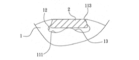
本発明の一実施例によるモータにおける回転子の構造は、多数の珪素鋼板1を積み重ねて構成され、各珪素鋼板1の周縁には等距離を置いた窪みを呈する磁性材料2を収容するための収容部11が多数設けられ、本実施例では、前記磁性材料2は永久磁石であり、前記収容部11は底面111と開口112とを有し、前記収容部11は底面111から上へ収縮する形態を呈し、且つ前記底面111と前記開口112とは二側面113で連続し、前記二側面113は外から内へ大きくなる斜面を呈し、なお、前記二側面113と収容部11にある底面111との接する箇所には窪み部12が設けられ、なお、前記収容部11の底面111には開口112方向に突起する突部12が設けられ、前記突部12が底面111の中央に位置し、前記磁性材料2を前記収容部11に嵌め込むときに、前記磁性材料2が前記突部12の上縁に当接し、なお、前記珪素鋼板1の中心部にはモータシャフトを挿入するための固定孔14が開けられている。
The structure of the rotor in the motor according to one embodiment of the present invention is configured by stacking a large number of
前記磁性材料2を収容部11内に嵌め込むときに、収容部11の開口112は磁性材料2に押されて微量の変形が発生し、前記変形量が収容部11の開口112の寸法を大きくし、そうすると、磁性材料2の収容部11内への嵌め込みが順調にできる。なお、前記磁性材料2を収容部11内に嵌め込むときに、押されて変形する開口112は変形によって発生する弾力により磁性材料2をしっかりと挟み、且つ収容部11の底面111の幅が開口112の幅より大きいので、磁性材料2は収容部11内にもっと安定して固定されることができ、高速で回転しても、収容部11から離脱することが発生しない。
When the
また、当該固定子4は電磁磁石なので、前記固定子4とモータの回転子とに電源を入れるときに、前記固定子4は回転子にある磁性材料2と作用して磁界を発生してモータを回転させ、且つ磁性材料2が収容部11にある突部13の上縁と当接するので、前記回転子が回転するときに、磁性材料2が固定子4の電磁磁石と作用して磁界を発生し、図3に示すように、前記磁界は正弦波形を呈し、且つ前記磁性材料2と固定子4とで発生する正弦波形磁界は起動がスムーズで、起動電流が少なく、定位精度が高いなどの特性を有するので、駆動回路がより複雑でコストがより高い特性を持つ設備に適用でき、例えば、精密タイプの工作機械や国防工業や精密バルブの角度制御などに適用できる。
Further, since the stator 4 is an electromagnetic magnet, when the power is supplied to the stator 4 and the rotor of the motor, the stator 4 acts on the
また、図4に示すように、収容部11が珪素鋼板1の周縁に位置しているので、磁性材料2を収容部11内に嵌め込む場合に、隙間Hが最小になり、モータの効率が向上する。
上記に述べるように、本実施例に係るモータや発電機における回転子の構造は、収容部11と珪素鋼板1との形態により、磁性材料2を収容部11内に安定して固定でき、且つ磁性材料2を収容部11内に嵌めて固定するときに、磁性材料2が前記突部13の上縁に当接するので、電源を入れて回転子を回転させると、前記磁性材料2は固定子4と作用して正弦波形の磁界を発生し、且つ前記正弦波形磁界は従来のモータのように極めて複雑な制御回路が必要ない。
Moreover, as shown in FIG. 4, since the
As described above, the structure of the rotor in the motor or the generator according to the present embodiment can stably fix the
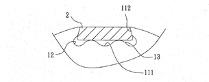
もちろん、本発明の実施例は他にまた沢山あり、それらは詳細の変化だけである。図5及び図6を参照する。これは、本発明の第二実施例であり、当該収容部11の底面111には二突部13が設けられ、前記二突部13は底面111から開口112の方向へ突起する形態を呈し、且つ前記二突部13が前記底面111の中央の両側に位置し、磁性材料2を前記収容部11に嵌め込むときに、前記磁性材料2が前記二突部13の上縁に当接する。
Of course, there are many other embodiments of the present invention, which are only changes in detail. Please refer to FIG. 5 and FIG. This is a second embodiment of the present invention, the
磁性材料2を前記収容部11に嵌め込むときに、前記磁性材料2が前記二突部13の上縁に当接するので、前記固定子4と回転子とに電源を入れると、前記固定子4が回転子にある磁性材料2と作用して磁界を発生してモータを回転させ、図6に示すように、前記磁界は台形波形を呈する。
When the
また、台形波形の磁界によれば、同様の体積及び定格電圧のものであっても、その起動トルク及び瞬間トルクがより大きくなるので、電動フォークリフトや高負荷の電動運輸バスなどに適用できる。 Further, according to the trapezoidal waveform magnetic field, even when the volume and the rated voltage are the same, the starting torque and the instantaneous torque are increased, so that it can be applied to an electric forklift or a high-load electric transportation bus.
上記の実施例は本発明を説明するために挙げた例であり、本発明の特許請求範囲を限定するためのものではないので、例えば、数値の変更や、モータ又は発電機の置換や、機械的な挟み作用などの同様な効果を持つ部品の置換は、全て本発明の特許請求範囲に属する。 The above embodiments are examples for explaining the present invention and are not intended to limit the scope of claims of the present invention. For example, changes in numerical values, replacement of motors or generators, machinery All replacements of parts having similar effects such as a pinching action are within the scope of the claims of the present invention.
1 珪素鋼板、2 磁性材料、4 固定子、11 収容部、12 窪み部、13 突部、14 貫通孔、111 底面、112 開口、113 側面、H 隙間
DESCRIPTION OF
Claims (4)
Priority Applications (1)
| Application Number | Priority Date | Filing Date | Title |
|---|---|---|---|
| JP2004095228A JP2005287138A (en) | 2004-03-29 | 2004-03-29 | Structure of motor rotor |
Applications Claiming Priority (1)
| Application Number | Priority Date | Filing Date | Title |
|---|---|---|---|
| JP2004095228A JP2005287138A (en) | 2004-03-29 | 2004-03-29 | Structure of motor rotor |
Publications (1)
| Publication Number | Publication Date |
|---|---|
| JP2005287138A true JP2005287138A (en) | 2005-10-13 |
Family
ID=35184947
Family Applications (1)
| Application Number | Title | Priority Date | Filing Date |
|---|---|---|---|
| JP2004095228A Pending JP2005287138A (en) | 2004-03-29 | 2004-03-29 | Structure of motor rotor |
Country Status (1)
| Country | Link |
|---|---|
| JP (1) | JP2005287138A (en) |
Citations (4)
| Publication number | Priority date | Publication date | Assignee | Title |
|---|---|---|---|---|
| JPH027842A (en) * | 1988-03-30 | 1990-01-11 | Aisin Seiki Co Ltd | Rotary machine |
| JPH0284032A (en) * | 1988-04-25 | 1990-03-26 | Matsushita Electric Works Ltd | Permanent magnet rotor |
| JP2002136010A (en) * | 2000-10-20 | 2002-05-10 | Yaskawa Electric Corp | AC servo motor rotor yoke |
| JP2003264948A (en) * | 2002-03-11 | 2003-09-19 | Tamagawa Seiki Co Ltd | Rotor structure |
-
2004
- 2004-03-29 JP JP2004095228A patent/JP2005287138A/en active Pending
Patent Citations (4)
| Publication number | Priority date | Publication date | Assignee | Title |
|---|---|---|---|---|
| JPH027842A (en) * | 1988-03-30 | 1990-01-11 | Aisin Seiki Co Ltd | Rotary machine |
| JPH0284032A (en) * | 1988-04-25 | 1990-03-26 | Matsushita Electric Works Ltd | Permanent magnet rotor |
| JP2002136010A (en) * | 2000-10-20 | 2002-05-10 | Yaskawa Electric Corp | AC servo motor rotor yoke |
| JP2003264948A (en) * | 2002-03-11 | 2003-09-19 | Tamagawa Seiki Co Ltd | Rotor structure |
Similar Documents
| Publication | Publication Date | Title |
|---|---|---|
| JP6667084B2 (en) | Surface magnet type motor | |
| JP5210150B2 (en) | Permanent magnet type rotating electrical machine, elevator apparatus, and manufacturing method of permanent magnet type rotating electrical machine | |
| JP4738759B2 (en) | Permanent magnet motor | |
| CN103872869B (en) | Multiple level formula electric rotating machine | |
| US20100289370A1 (en) | Synchronous motor having 12 stator teeth and 10 rotor poles | |
| JP2017022970A (en) | Single-phase outer-rotor motor and rotor thereof | |
| KR19980701526A (en) | D.C.BRUSHLESS MOTOR WITH MINIMIZED NET RADIAL FORCESAND LOW COGGING TORQUE with Minimal Radial Netting Force and Low Cogging Torque | |
| CN102480195A (en) | Rotating electric machine and method for manufacturing rotating electric machine | |
| JP2013230047A (en) | Rotor for motor, and motor | |
| JP2015204732A (en) | motor | |
| JP2017063599A (en) | Single phase brushless motor and power tool using the same | |
| JP2008131683A (en) | Axial air gap type electric motor | |
| US11888355B2 (en) | Rotor and motor including same | |
| JP5789182B2 (en) | Generator | |
| CN115622278B (en) | Motors including stators with tooth profiles that reduce parasitic voltage | |
| WO2023189285A1 (en) | Rotor and electric motor | |
| JP2013115836A (en) | Brushless motor and electric pump | |
| JP2020014368A (en) | Brushless motor and brushless motor manufacturing method | |
| JP6721254B2 (en) | Outer rotor type brushless motor | |
| JP2018093586A (en) | Rotary electric machine | |
| JP7599164B2 (en) | Motor | |
| KR200420759Y1 (en) | Generator and motor stator | |
| JP2005261045A (en) | Electric machine | |
| JP7567648B2 (en) | Rotating Electric Machine | |
| JP2015186422A (en) | Permanent magnet-embedded rotor for rotary electric machine, and rotary electric machine |
Legal Events
| Date | Code | Title | Description |
|---|---|---|---|
| A977 | Report on retrieval |
Free format text: JAPANESE INTERMEDIATE CODE: A971007 Effective date: 20060525 |
|
| A131 | Notification of reasons for refusal |
Free format text: JAPANESE INTERMEDIATE CODE: A131 Effective date: 20060601 |
|
| A02 | Decision of refusal |
Free format text: JAPANESE INTERMEDIATE CODE: A02 Effective date: 20061026 |