JP2005287256A - Digital protecting and controlling device and its display data production method, and display data production program - Google Patents
Digital protecting and controlling device and its display data production method, and display data production program Download PDFInfo
- Publication number
- JP2005287256A JP2005287256A JP2004101493A JP2004101493A JP2005287256A JP 2005287256 A JP2005287256 A JP 2005287256A JP 2004101493 A JP2004101493 A JP 2004101493A JP 2004101493 A JP2004101493 A JP 2004101493A JP 2005287256 A JP2005287256 A JP 2005287256A
- Authority
- JP
- Japan
- Prior art keywords
- phase
- display
- display data
- reference element
- electric quantity
- Prior art date
- Legal status (The legal status is an assumption and is not a legal conclusion. Google has not performed a legal analysis and makes no representation as to the accuracy of the status listed.)
- Pending
Links
- 238000004519 manufacturing process Methods 0.000 title 1
- 238000000034 method Methods 0.000 claims description 33
- 230000003111 delayed effect Effects 0.000 claims description 14
- 230000005611 electricity Effects 0.000 claims description 13
- 238000006243 chemical reaction Methods 0.000 claims description 12
- 238000005070 sampling Methods 0.000 claims description 8
- 230000005612 types of electricity Effects 0.000 claims 3
- 230000005540 biological transmission Effects 0.000 abstract description 6
- 230000002747 voluntary effect Effects 0.000 abstract 1
- 238000010586 diagram Methods 0.000 description 20
- 230000000694 effects Effects 0.000 description 10
- 238000012986 modification Methods 0.000 description 3
- 230000004048 modification Effects 0.000 description 3
- 230000004397 blinking Effects 0.000 description 1
- 230000002195 synergetic effect Effects 0.000 description 1
Images






Landscapes
- Emergency Protection Circuit Devices (AREA)
- Measuring Phase Differences (AREA)
Abstract
Description
本発明は、電力系統の電気量を、アナログ入力回路を介して入力し、電力系統の事故の有無を判別するディジタル形保護制御装置において、特に、電力系統の電気量を表示するための表示データの作成に関するものである。 The present invention relates to a digital protection control device that inputs an electric quantity of an electric power system via an analog input circuit and discriminates whether or not an electric power system has an accident. In particular, display data for displaying the electric quantity of an electric power system It is about making.
従来、電力系統を保護制御する保護制御装置としては種々のものがあるが、最近では、マイクロコンピュータ等のディジタル演算処理手段を用いて電力系統の保護制御を行う、いわゆるディジタル形保護制御装置が多く採用されている。 Conventionally, there are various protection control devices for protecting and controlling the power system. Recently, there are many so-called digital protection control devices that perform protection control of the power system using digital arithmetic processing means such as a microcomputer. It has been adopted.
このディジタル形保護制御装置は、系統からアナログ入力回路に入力される電圧・電流などの電気量を所定のサンプリング周波数でアナログ/ディジタル変換した後、そのディジタル信号を取込んで系統保護制御に必要な演算処理を行うものである。例えば、整定条件に基づいて電力系統の状態を判定する演算処理手段と、この演算処理手段とシステムバスを介して接続され、整定条件を外部より入力可能なCPUを内蔵するマンマシンインタフェース手段とを有し、演算処理手段の判定により、整定条件を満たすときにはリレー動作をさせる保護制御装置が存在している(例えば、特許文献1参照)。
このようなディジタル形保護制御装置は、一般的に、電力系統から得られる電圧・電流などの電気量を、電力系統の状態を示す電気量データとして画面上に表示する機能を有する。図18は、従来のディジタル形保護制御装置によって表示される入力電気量表示画面の画面例を示す図である。 Such a digital protection control device generally has a function of displaying an electric quantity such as voltage / current obtained from the electric power system on the screen as electric quantity data indicating the state of the electric power system. FIG. 18 is a diagram showing a screen example of an input electric quantity display screen displayed by a conventional digital protection control device.
ここで、図18の(a)は、アナログ入力回路に入力される電気量をアナログ/ディジタル変換して得られるディジタル信号を使用して、演算処理手段により各電気量要素相互間の位相差および実効値を演算し、その演算結果を入力電気量表示画面11として表示した画面例である。この画面例では、電気量要素として、3相の電圧要素Va,Vb,Vcと3相の電流要素Ia,Ib,Icをそれぞれ表示している。なお、この画面例において、各要素の位相情報については、電圧の第1相(Va)を位相表示用の位相基準として算出した場合における、各電気量要素のVaに対する相対位相を、Vaの位相に対して遅れ方向を正とする遅れ位相表示で示している。
Here, FIG. 18A shows a phase difference between each electrical quantity element by an arithmetic processing means using a digital signal obtained by analog / digital conversion of the electrical quantity inputted to the analog input circuit. It is a screen example in which an effective value is calculated and the calculation result is displayed as an input electric
また、図18の(b)は、図18の(a)と同じ形式の画面例であるが、位相基準として設定したVaの実効値がゼロの状態を示している。この図18の(b)に示す画面例は、位相基準であるVaの実効値がゼロのため、位相基準を用いて位相差を算出することが不可能となり、その他の電気量の位相表示ができなくなった状態を示している。 FIG. 18B shows a screen example of the same format as FIG. 18A, but shows a state where the effective value of Va set as the phase reference is zero. In the screen example shown in FIG. 18B, since the effective value of Va as the phase reference is zero, it is impossible to calculate the phase difference using the phase reference, and the phase display of other electric quantities is possible. Indicates a state where it is no longer possible.
上述したように、従来のディジタル形保護制御装置における電気量データの表示方式では、位相表示をする場合に、位相表示用の位相基準として選択される要素が、予め固定的に設定されている。そのため、表示データを取り扱うための自由度が不足しており、表示データの有効活用に限界があった。また、位相基準要素が固定的に設定されているため、図18の(b)に示すように、位相基準要素の電気量入力がないか若しくは非常に小さく、十分な実効値が得られない場合には、位相表示を正常に行うことができなくなる可能性があった。さらに、位相表示方法についても、位相基準に対する進み位相表示または遅れ位相表示のいずれかに予め固定的に設定されているため、この点からも、表示データを取扱うための自由度が不足しており、表示データの有効活用に限界があった。 As described above, in the display method of electric quantity data in the conventional digital protection control device, the element selected as the phase reference for phase display is fixedly set in advance when performing phase display. Therefore, the degree of freedom for handling display data is insufficient, and there is a limit to the effective use of display data. In addition, since the phase reference element is fixedly set, as shown in FIG. 18B, there is no electrical quantity input of the phase reference element or it is very small, and a sufficient effective value cannot be obtained. Therefore, there is a possibility that the phase display cannot be performed normally. Furthermore, the phase display method is also fixed in advance to either the lead phase display or the lag phase display with respect to the phase reference, and from this point, the degree of freedom for handling display data is insufficient. There was a limit to the effective use of display data.
本発明は、上記課題を解決するためになされたものであり、その目的は、表示データの柔軟な取り扱いと有効活用が実現可能で、位相基準要素の十分な実効値が得られない場合でも位相表示を正常に行うことが可能な、ディジタル形保護制御装置とその表示データ作成方法、および表示データ作成プログラムを提供することである。 The present invention has been made in order to solve the above-described problems, and its purpose is to realize flexible handling and effective use of display data, and even when a sufficient effective value of a phase reference element cannot be obtained. To provide a digital protection control device, a display data creation method thereof, and a display data creation program capable of performing normal display.
本発明は、上記のような目的を達成するために、ユーザからの指定に応じて位相表示用の位相基準要素を選択し、この位相基準要素の位相を基準とする位相表示データを作成することにより、表示データの柔軟な取り扱いと有効活用が実現でき、位相基準要素の十分な実効値が得られない場合でも位相表示を正常に行うことができるようにしたものである。 In order to achieve the above object, the present invention selects a phase reference element for phase display in accordance with a designation from a user, and creates phase display data based on the phase of the phase reference element. Thus, flexible handling and effective utilization of display data can be realized, and phase display can be normally performed even when a sufficient effective value of the phase reference element cannot be obtained.
請求項1の発明は、所定の基本周波数を有する複数種類の電気量を入力し、所定のサンプリング周波数でアナログ/ディジタル変換した後の電気量データを表示するディジタル形保護制御装置において、位相算出手段、位相基準選択手段、位相表示データ作成手段、を備えたことを特徴としている。ここで、位相算出手段は、複数種類の電気量の各電気量要素について位相を算出する手段である。また、位相基準選択手段は、ユーザからの指定に応じて、複数種類の電気量の中から任意の電気量要素を位相表示用の位相基準要素として選択する手段である。さらに、位相表示データ作成手段は、算出された位相と選択された位相基準要素に基づき、当該位相基準要素の位相を基準として、他の電気量要素については、当該位相基準要素の位相との差分を表示する位相表示データを作成して画面上に表示する手段である。 According to a first aspect of the present invention, there is provided a digital protection control apparatus for inputting a plurality of types of electric quantities having a predetermined fundamental frequency and displaying electric quantity data after analog / digital conversion at a predetermined sampling frequency. And a phase reference selection means and a phase display data creation means. Here, the phase calculation means is means for calculating a phase for each electric quantity element of plural kinds of electric quantities. The phase reference selection means is means for selecting an arbitrary electric quantity element from among a plurality of types of electric quantities as a phase reference element for phase display in accordance with a designation from the user. Further, the phase display data creation means is based on the calculated phase and the selected phase reference element, and the difference between the phase reference element and the phase of the phase reference element for other electrical quantity elements based on the phase of the phase reference element. Is a means for generating phase display data for displaying and displaying it on the screen.
この発明によれば、ユーザからの指定に応じて、任意の電気量要素を位相表示用の位相基準要素として選択し、この位相基準要素の位相を基準として、他の電気量要素については、当該位相基準要素の位相との差分を表示する位相表示データを作成することができる。したがって、位相基準要素を自由に選択できるため、表示データの柔軟な取り扱いと有効活用が実現できる。また、一旦選択した任意の位相基準要素について十分な実効値が得られない場合でも、別の電気量要素を新たな位相基準要素として選択することにより、位相表示を正常に行うことができる。 According to the present invention, an arbitrary electric quantity element is selected as a phase reference element for phase display according to the designation from the user, and with respect to the other electric quantity elements based on the phase of the phase reference element, Phase display data for displaying the difference from the phase of the phase reference element can be created. Therefore, since the phase reference element can be freely selected, flexible handling and effective use of display data can be realized. Further, even when a sufficient effective value cannot be obtained for any selected phase reference element, phase display can be performed normally by selecting another electric quantity element as a new phase reference element.
以上のように、本発明によれば、ユーザからの指定に応じて位相表示用の位相基準要素を選択し、この位相基準要素の位相を基準とする位相表示データを作成することにより、表示データの柔軟な取り扱いと有効活用が実現可能で、位相基準要素の十分な実効値が得られない場合でも位相表示を正常に行うことが可能な、ディジタル形保護制御装置とその表示データ作成方法、および表示データ作成プログラムを提供することができる。 As described above, according to the present invention, display data is selected by selecting a phase reference element for phase display in accordance with a designation from the user and creating phase display data based on the phase of this phase reference element. Digital protection control device capable of performing phase display normally even when a sufficient effective value of the phase reference element cannot be obtained, and its display data creation method, A display data creation program can be provided.
以下には、本発明を適用した実施形態について、図面を参照して具体的に説明する。 Embodiments to which the present invention is applied will be specifically described below with reference to the drawings.
[第1の実施形態]
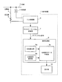
図1は、本発明を適用した第1の実施形態におけるディジタル形保護制御装置の表示装置を示すブロック図である。この図1において、表示装置1には、電力系統の母線2に設けられた変成器3と送電線4に設けられた変流器5より、電圧と電流の電気量がそれぞれ入力されるようになっている。
[First Embodiment]
FIG. 1 is a block diagram showing a display device of a digital protection control device according to a first embodiment to which the present invention is applied. In FIG. 1, the
この表示装置1は、母線2の変成器3と送電線4の変流器5より電圧および電流の電気量をそれぞれアナログ入力する入力変換器6、入力された電気量をディジタル変換するアナログ/ディジタル変換器7、変換されたディジタル信号8を取込み、表示データを作成する演算処理部(ディジタル演算処理手段)9、および、作成された表示データを画面表示する表示部10、を備えている。
This
演算処理部9は、各電気量要素の位相を算出する位相算出部(位相算出手段)9a、ユーザからの指定に応じて、任意の電気量要素を位相表示用の位相基準要素として選択する位相基準選択部(位相基準選択手段)9b、および、選択された位相基準要素の位相を基準とする位相表示データを作成して画面上に表示する位相表示データ作成部(位相表示データ作成手段)9c、を備えている。
The
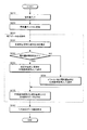
図2は、図1に示す表示装置1の動作の概要を示すフローチャートである。この図2に示すように、母線2の変成器3と送電線4の変流器5より、電圧および電流の電気量が入力変換器6にアナログ入力されると(S210)、入力された電気量は、アナログ/ディジタル変換器7により所定のサンプリング周波数でディジタル信号8に変換され、演算処理部9に与えられる(S220)。演算処理部9では、表示データ作成処理(S230)として、次のような一連の処理を行う。
FIG. 2 is a flowchart showing an outline of the operation of the
まず、位相算出部9aにより、ディジタル信号8の各電気量要素の絶対位相を算出する(S231)。次に、位相基準選択部9bにより、ユーザから位相基準要素として何らかの電気量要素が指定されているか否かを判定する(S232)。位相基準選択部9bは、電気量要素が指定されている場合(S232のYES)には、その指定された電気量要素を位相基準要素として選択する(S233)。また、ユーザからの指定がない場合(S232のNO)には、デフォルト値として予め設定された電気量要素を位相基準要素として選択する(S234)。
First, the absolute phase of each electric quantity element of the digital signal 8 is calculated by the
続いて、位相表示データ作成部9cにより、算出された絶対位相と選択された位相基準要素に基づき、当該位相基準要素の位相を基準として、他の電気量要素については、当該位相基準要素の位相との差分を表示する位相表示データを作成する(S235)。作成された位相表示データは、表示部10に与えられ、画面表示される(S240)。
Subsequently, on the basis of the phase of the phase reference element based on the calculated absolute phase and the selected phase reference element by the phase display
図3は、第1の実施形態において、表示部10により位相表示データを入力電気量表示画面11として表示した画面例を示す図であり、図18に示した画面例と同様に、電気量要素として、3相の電圧要素Va,Vb,Vcと3相の電流要素Ia,Ib,Icについて、位相差と実効値をそれぞれ表示している。ここで、図3の(a)は、入力電気量表示画面11において、位相基準要素として電圧の第1相Vaを選択し、その他の電気量要素については、各電気量要素のVaに対する相対位相を、Vaの位相に対して遅れ方向を正とする遅れ位相表示で示している。
FIG. 3 is a diagram illustrating a screen example in which the phase display data is displayed as the input electrical
また、図3の(b)は、位相基準要素として電圧の第2相Vbを選択し、その他の電気量要素をVbに対する遅れ位相表示で示しており、図3の(c)は、位相基準要素として電流の第1相Iaを選択し、その他の電気量要素をIaに対する遅れ位相表示で示している。なお、図3の(a)〜(c)において、個々の電気量要素を特定する符号のうち、位相基準要素を特定する符号を含む矩形の表示領域12については、図中では、符号を太字とし、囲み線を施して示しているが、実際には、他の部分と異なる色を使用するなどの表示形式により強調的に表示される。この場合、表示領域12は、位相基準要素を特定する情報であり、本発明における位相基準要素特定情報に相当する。
FIG. 3B shows the second phase Vb of the voltage selected as the phase reference element, and other electric quantity elements are shown in a delayed phase display with respect to Vb. FIG. 3C shows the phase reference element. The first phase Ia of the current is selected as an element, and the other electric quantity elements are indicated by a delayed phase display with respect to Ia. 3A to 3C, among the codes that specify individual electric quantity elements, the
以上のような第1の実施形態によれば、ユーザからの指定に応じて、任意の電気量要素を位相表示用の位相基準要素として選択し、この位相基準要素の位相を基準として、他の電気量要素については、当該位相基準要素の位相との差分を表示する位相表示データを作成することができるため、入力電気量表示画面11にユーザである運用者が意図した通りの電気量の位相表示を柔軟に行うことが可能となる。すなわち、位相基準要素を自由に選択できるため、表示データの柔軟な取り扱いと有効活用が実現できる。
According to the first embodiment as described above, an arbitrary electric quantity element is selected as a phase reference element for phase display in accordance with the designation from the user, and the phase of this phase reference element is used as a reference for other As for the electric quantity element, phase display data for displaying the difference from the phase of the phase reference element can be created. Therefore, the phase of the electric quantity as intended by the operator who is the user is displayed on the input electric
また、一旦選択した任意の位相基準要素について十分な実効値が得られない場合でも、別の電気量要素を新たな位相基準要素として選択することにより、位相表示を正常に行うことができる。さらに、位相基準要素を特定する符号を含む表示領域12を色分けなどの表示形式で強調的に表示することにより、ユーザである運用者が、表示内容を確認する際に、どの要素が位相表示の基準となっているかを容易に認識することが可能な、より理解し易く取り扱い易い入力電気量表示画面11を提供できる。
Further, even when a sufficient effective value cannot be obtained for any selected phase reference element, phase display can be performed normally by selecting another electric quantity element as a new phase reference element. Furthermore, by highlighting the
[第1の実施形態の変形例]
また、前記第1の実施形態の変形例として、位相表示データ作成部9cにより、位相基準要素の位相に対して、進み方向を正とする進み位相表示と遅れ方向を正とする遅れ位相表示のいずれの位相表示方向であるかを示す何らかの位相表示方向種別を入力電気量表示画面11上に付加的に表示することも可能である。図4の入力電気量表示画面11においては、そのような位相表示方向種別の一例として、正とする位相表示方向が遅れ方向であることを明示する「位相は遅れ表示」の文字列13aが付加的に表示されている。
[Modification of First Embodiment]
Further, as a modification of the first embodiment, the phase display
このように、文字列13aなどの位相表示方向種別を画面上に明示することにより、ユーザである運用者が、表示内容を確認する際に、より理解し易く取り扱い易い入力電気量表示画面11を提供できる。
In this way, by specifying the phase display direction type such as the character string 13a on the screen, the input electric
[第2の実施形態]
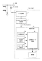
図5は、本発明を適用した第2の実施形態におけるディジタル形保護制御装置の表示装置を示すブロック図である。この図5に示すように、第2の実施形態は、第1の実施形態における演算処理部9を変更したものであり、位相基準選択部9bによって選択された位相基準要素に基づき、位相算出部9aによって位相基準要素を基準としたその他の電気量要素の相対位相を算出するようにしたものである。なお、他の構成については、第1の実施形態と全く同様である。
[Second Embodiment]
FIG. 5 is a block diagram showing a display device of the digital protection control device according to the second embodiment to which the present invention is applied. As shown in FIG. 5, the second embodiment is a modification of the
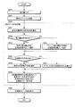
図6は、図5に示す表示装置1の動作の概要を示すフローチャートである。この図6において、電気量入力(S610)、電気量ディジタル変換(S620)、表示データ作成処理(S630)、位相表示データ画面表示(S640)は、図2における下二桁が同一番号の各ステップS210、S220、S230、S240、とそれぞれ対応している。そして、表示データ作成処理(S630)の一部のみが、図2の表示データ作成処理(S230)と異なっている。
FIG. 6 is a flowchart showing an outline of the operation of the
すなわち、第2の実施形態の演算処理部9では、表示データ作成処理(S630)として、位相を算出する前に、位相基準選択部9bにより、ユーザから位相基準要素として何らかの電気量要素が指定されているか否かを判定し(S631)、電気量要素の指定の有無に応じて、指定された電気量要素またはデフォルト値の電気量要素を位相基準要素として選択する(S632、S633)。このように電気量要素指定の有無を判定して位相基準要素を選択する一連の動作(S631〜S633)自体は、図2の一連の動作(S232〜S234)と同様である。
That is, in the
第2の実施形態では、このような位相基準要素の選択を行った後に、位相算出部9aにより、選択された位相基準要素の位相を基準とし、他の各電気量要素については、当該位相基準要素の位相に対する相対位相を算出する(S634)。そして、位相表示データ作成部9cは、選択された位相基準要素と算出された相対位相とに基づき、位相表示データを作成する(S635)。
In the second embodiment, after such a phase reference element is selected, the
以上のような第2の実施形態は、表示データ作成処理の手順が前記第1の実施形態と異なっているが、得られる効果は第1の実施形態と全く同様である。 In the second embodiment as described above, the procedure of the display data creation process is different from that of the first embodiment, but the obtained effect is exactly the same as that of the first embodiment.
[第3の実施形態]
図7は、本発明を適用した第3の実施形態におけるディジタル形保護制御装置の表示装置を示すブロック図である。この図7に示すように、第3の実施形態は、第1の実施形態における演算処理部9に、位相基準要素の位相に対して、進み方向を正とする進み位相表示と遅れ方向を正とする遅れ位相表示のいずれの位相表示を行うかを選択する進み/遅れ選択部(進み/遅れ選択手段)9dを追加したものである。また、位相表示データ作成部9cは、選択された位相表示方向を示す位相表示方向種別を入力電気量表示画面11上に付加的に表示するようになっている。なお、他の構成については、第1の実施形態と全く同様である。
[Third Embodiment]
FIG. 7 is a block diagram showing a display device of a digital protection control device according to a third embodiment to which the present invention is applied. As shown in FIG. 7, in the third embodiment, the
図8は、図7に示す表示装置1の動作の概要を示すフローチャートである。この図8において、電気量入力(S810)、電気量ディジタル変換(S820)、表示データ作成処理(S830)、位相表示データ画面表示(S840)は、図2における下二桁が同一番号の各ステップS210、S220、S230、S240、とそれぞれ対応している。そして、表示データ作成処理(S830)の一部のみが、図2の表示データ作成処理(S230)と異なっている。
FIG. 8 is a flowchart showing an outline of the operation of the
まず、第3の実施形態の演算処理部9により、表示データ作成処理(S830)として、各電気量要素の絶対位相を算出し、電気量要素指定の有無を判定して位相基準要素を選択するまでの一連の動作(S831〜S834)は、図2の一連の動作(S231〜S234)と同様である。第3の実施形態においては、このような位相基準要素の選択を行った後に、進み/遅れ選択部9dにより、ユーザから進み位相表示と遅れ位相表示のいずれかの位相表示方向が指定されているか否かを判定する(S835)。
First, as the display data creation process (S830), the
進み/遅れ選択部9dは、位相表示方向が指定されている場合(S835のYES)には、その指定された位相表示方向を選択し(S836)、ユーザからの指定がない場合(S835のNO)には、デフォルト値として予め設定された位相表示方向(例えば、遅れ位相表示)を選択する(S837)。続いて、位相表示データ作成部9cにより、算出された絶対位相と選択された位相基準要素に基づき、選択された位相表示方向の位相表示データを、その位相表示方向を示す位相表示方向種別を含めて作成する(S838)。
When the phase display direction is designated (YES in S835), the advance /
図9は、第3の実施形態において、表示部10により、位相表示方向種別を含む位相表示データを入力電気量表示画面11として表示した画面例を示す図であり、図3に示した画面例と同様に、3相の電圧要素Va,Vb,Vcと3相の電流要素Ia,Ib,Icについて、位相差と実効値をそれぞれ表示している。この例では、入力電気量表示画面11において、位相基準要素として電圧の第1相Vaを選択し、その他の電気量要素については、各電気量要素のVaに対する相対位相を、Vaの位相に対する進み位相表示で示している。また、この図9の入力電気量表示画面11においては、位相表示方向種別として、正とする位相表示方向が進み方向であることを明示する「位相は進み表示」の文字列13aが付加的に表示されている。
FIG. 9 is a diagram showing a screen example in which the phase display data including the phase display direction type is displayed as the input electric
以上のような第3の実施形態によれば、前記第1の実施形態と同様の効果が得られることに加えて、さらに次のような効果が得られる。ユーザからの指定に応じて、進み位相表示と遅れ位相表示のいずれかの位相表示方向を選択し、選択された位相表示方向の位相表示データを、その位相表示方向を示す位相表示方向種別を含めて作成することができるため、入力電気量表示画面11にユーザである運用者が意図した通りの進み位相表示または遅れ位相表示を柔軟に行うことが可能となる。すなわち、進み位相表示または遅れ位相表示のいずれかを自由に選択できるため、表示データのより柔軟な取り扱いと一層の有効活用が実現できる。
According to the third embodiment as described above, in addition to the same effects as those of the first embodiment, the following effects are further obtained. According to the specification from the user, either the phase display direction of the lead phase display or the delay phase display is selected, and the phase display data of the selected phase display direction includes the phase display direction type indicating the phase display direction. Therefore, the advanced phase display or the delayed phase display as intended by the user operator can be flexibly performed on the input electric
さらに、文字列13aなどの位相表示方向種別を画面上に明示することにより、ユーザである運用者が、表示内容を確認する際に、より理解し易く取り扱い易い入力電気量表示画面11を提供できる。
Further, by clearly indicating the phase display direction type such as the character string 13a on the screen, it is possible to provide the input electric
[第4の実施形態]
図10は、本発明を適用した第4の実施形態におけるディジタル形保護制御装置の表示装置を示すブロック図である。この図10に示すように、第4の実施形態は、第1の実施形態における演算処理部9に、位相基準選択部9bによって選択された位相基準要素を記憶する位相基準要素記憶部9eを追加したものである。また、位相表示データ作成部9cは、位相表示データが進み位相表示であるか遅れ位相表示であるかを示す位相表示方向種別と、記憶された位相基準要素を特定する位相基準特定情報を、入力電気量表示画面11上に付加的に表示するようになっている。なお、他の構成については、第1の実施形態と全く同様である。
[Fourth Embodiment]
FIG. 10 is a block diagram showing a display device of the digital protection control device in the fourth embodiment to which the present invention is applied. As shown in FIG. 10, in the fourth embodiment, a phase reference element storage unit 9e that stores the phase reference element selected by the phase
図11は、図10に示す表示装置1の動作の概要を示すフローチャートである。この図11において、電気量入力(S1110)、電気量ディジタル変換(S1120)、表示データ作成処理(S1130)、位相表示データ画面表示(S1140)は、図2における下二桁が同一番号の各ステップS210、S220、S230、S240、とそれぞれ対応している。そして、表示データ作成処理(S1130)の一部のみが、図2の表示データ作成処理(S230)と異なっている。
FIG. 11 is a flowchart showing an outline of the operation of the
まず、第4の実施形態の演算処理部9により、表示データ作成処理(S1130)として、各電気量要素の絶対位相を算出し、電気量要素指定の有無を判定して位相基準要素を選択するまでの一連の動作(S1131〜S1134)は、図2の一連の動作(S231〜S234)と同様である。第4の実施形態においては、このような位相基準要素の選択を行った後に、位相基準要素記憶部9eにより、選択された位相基準要素を特定する位相基準特定情報を記憶する(S1135)。続いて、位相表示データ作成部9cにより、算出された絶対位相と選択された位相基準要素に基づき、選択された位相表示方向の位相表示データを、その位相表示方向を示す位相表示方向種別および位相基準要素を特定する位相基準特定情報を含めて作成する(S1136)。
First, as the display data creation process (S1130), the
図12は、第4の実施形態において、表示部10により、位相表示方向種別および位相基準特定情報を含む位相表示データを入力電気量表示画面11として表示した画面例を示す図であり、図3に示した画面例と同様に、3相の電圧要素Va,Vb,Vcと3相の電流要素Ia,Ib,Icについて、位相差と実効値をそれぞれ表示している。この例では、入力電気量表示画面11において、位相基準要素として電圧の第1相Vaを選択し、その他の電気量要素については、各電気量要素のVaに対する相対位相を、Vaの位相に対する遅れ位相表示で示している。また、この図12の入力電気量表示画面11においては、位相表示方向種別として、正とする位相表示方向が遅れ方向であることを明示する「位相は遅れ表示」の文字列13aが付加的に表示されると共に、位相基準特定情報として、位相基準要素がVaであることを明示する「位相基準はVa」の文字列13bが付加的に表示されている。
FIG. 12 is a diagram showing a screen example in which the phase display data including the phase display direction type and the phase reference specifying information is displayed as the input electric
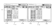
また、図12などに示す画面例においては、説明を簡略化するために単一の画面に全ての電気量が表示される場合について説明したが、実際には、各種の適用条件に応じて、全ての電気量を表示するための入力電気量表示画面が、画面切替方式で表示される複数の画面となる場合がある。図13、図14は、このように複数の入力電気量表示画面で全ての電気量を表示する場合の異なる画面例をそれぞれ示す図である。 Further, in the screen example shown in FIG. 12 and the like, the case where all the electric quantities are displayed on a single screen has been described in order to simplify the description, but actually, depending on various application conditions, There are cases where the input electric quantity display screen for displaying all electric quantities is a plurality of screens displayed by the screen switching method. FIG. 13 and FIG. 14 are diagrams respectively showing different screen examples when displaying all the electric quantities on the plurality of input electric quantity display screens.
まず、図13は、母線保護装置に適用した場合における複数の入力電気量表示画面11a,11bの画面例を示す図である。すなわち、母線保護装置では、母線につながる多数の送電線の電気量を扱っており、これらを全て表示させる必要があるため、入力電気量表示画面も複数必要となる。図13の例では、第1の入力電気量表示画面11aにおいて、3相の電圧要素Va,Vb,Vcと3相の電流要素1LIa,1LIb,1LIcを表示すると共に、第2の入力電気量表示画面11bにおいて、3相の電流要素2LIa,2LIb,2LIcと別の3相の電流要素3LIa,3LIb,3LIcを表示している。そして、両方の入力電気量表示画面11a,11bのそれぞれにおいて、位相表示方向種別と位相基準特定情報を示す両方の文字列13a,12bが付加的に表示されている。
First, FIG. 13 is a diagram showing a screen example of a plurality of input electric
また、図14は、表示画面自体の寸法が小さい場合における複数の入力電気量表示画面11a,11bの画面例を示す図である。この例では、1つの画面の表示が3行に限定されている場合を示しており、第1の入力電気量表示画面11aにおいて、3相の電圧要素Va,Vb,Vcを表示すると共に、第2の入力電気量表示画面11bにおいて、3相の電流要素Ia,Ib,Icを表示している。そして、両方の入力電気量表示画面11a,11bのそれぞれにおいて、位相表示方向種別と位相基準特定情報を示す両方の文字列13a,12bが付加的に表示されている。
FIG. 14 is a diagram showing a screen example of a plurality of input electric
以上のような第4の実施形態によれば、前記第1の実施形態と同様の効果が得られることに加えて、さらに次のような効果が得られる。すなわち、文字列13bなどの位相基準特定情報を画面上に明示することにより、ユーザである運用者が、表示内容を確認する際に、どの要素が位相表示の基準となっているかを容易に認識することが可能な、より理解し易く取り扱い易い入力電気量表示画面11を提供できる。また、文字列13aなどの位相表示方向種別を画面上に明示しているため、このことからも、入力電気量表示画面11をより理解し易く取り扱い易いものにすることができる。
According to the fourth embodiment as described above, the following effects can be obtained in addition to the same effects as those of the first embodiment. That is, by specifying phase reference specifying information such as the
特に、全ての電気量を複数の入力電気量表示画面を用いて画面切替方式で表示する場合には、例えば、表示されている側の画面に、位相基準要素が表示されない場合でも、位相基準特定情報が表示されることにより、ユーザである運用者は、現在の位相基準要素を常に画面上で確認することができる。例えば、図13において、第1の入力電気量表示画面11aから第2の入力電気量表示画面11bに画面切替された場合に、この第2の入力電気量表示画面11bには、現在の位相基準要素である電圧の第1相Vaは表示されないが、位相基準特定情報を示す「位相基準はVa」という文字列13bが表示されているため、第2の入力電気量表示画面11b上においても、現在の位相基準要素が電圧の第1相Vaであることを容易に確認することができる。
In particular, when all electric quantities are displayed using a screen switching method using a plurality of input electric quantity display screens, for example, even when the phase reference element is not displayed on the displayed screen, the phase reference is specified. By displaying the information, the operator who is the user can always check the current phase reference element on the screen. For example, in FIG. 13, when the screen is switched from the first input electricity display screen 11a to the second input
[第5の実施形態]
図15は、本発明を適用した第5の実施形態におけるディジタル形保護制御装置の表示装置を示すブロック図である。この図15に示すように、第5の実施形態は、第1の実施形態における演算処理部9に、位相基準切替部9fと実効値算出部9gを追加したものである。ここで、実効値算出部9gは、現在の位相基準要素の実効値を算出する部分であり、位相基準切替部9fは、実効値算出部9gからの実効値が予め設定された所定値以下である場合に、位相基準要素を自動的に他相または他電気量に切り替える部分である。実効値が所定値以下となる場合は、系統事故、設備停止、変成器等の不良など、各種の場合が考えられるが、ここでは、一例として、系統事故の場合について説明する。
[Fifth Embodiment]
FIG. 15 is a block diagram showing a display device of a digital protection control device according to a fifth embodiment to which the present invention is applied. As shown in FIG. 15, the fifth embodiment is obtained by adding a phase
また、位相表示データ作成部9cは、位相表示データが進み位相表示であるか遅れ位相表示であるかを示す位相表示方向種別と、現在または事故前の位相基準要素を特定する位相基準特定情報を、入力電気量表示画面11上に付加的に表示するようになっている。なお、他の構成については、第1の実施形態と全く同様である。
The phase display
図16は、図15に示す表示装置1の動作の概要を示すフローチャートである。この図16において、電気量入力(S1610)、電気量ディジタル変換(S1620)、表示データ作成処理(S1630)、位相表示データ画面表示(S1640)は、図2における下二桁が同一番号の各ステップS210、S220、S230、S240、とそれぞれ対応している。そして、表示データ作成処理(S1630)の一部のみが、図2の表示データ作成処理(S230)と異なっている。
FIG. 16 is a flowchart showing an outline of the operation of the
まず、第5の実施形態の演算処理部9により、表示データ作成処理(S1630)として、各電気量要素の絶対位相を算出し、電気量要素指定の有無を判定して位相基準要素を選択するまでの一連の動作(S1631〜S1634)は、図2の一連の動作(S231〜S234)と同様である。第5の実施形態においては、このような位相基準要素の選択を行った後に、系統事故が発生した場合(S1635のYES)は、実効値算出部9gにより、現在の位相基準要素の事故時実効値を算出してその結果を位相基準切替部9fに与える(S1636)。なお、図16は、系統事故の場合について説明しているが、これに限定されない。すなわち、図16のステップS1635の判断要素としては、系統事故以外にも、設備停止、変成器等の不良など、実効値が所定値以下となる各種の要素が該当する。
First, as the display data creation process (S1630), the
位相基準切替部9fは、実効値算出部9gからの実効値が予め設定された所定値以下である場合(S1637のYES)には、位相基準要素を自動的に他相または他電気量に切り替えて位相表示データ作成部9cに与える(S1638)。また、事故時でない通常時(S1635のNO)においては、位相基準切替部9fは、位相基準選択部9bによって選択された位相基準要素をそのまま位相表示データ作成部9cに与える。
The phase
位相表示データ作成部9cは、算出された絶対位相と与えられた位相基準要素に基づき、位相表示データを、その位相表示方向を示す位相表示方向種別および位相基準要素を特定する位相基準特定情報を含めて作成する(S1639)。
Based on the calculated absolute phase and the given phase reference element, the phase display
図17の(a)は、第5の実施形態において、表示部10により、事故時電気量の位相表示データを入力電気量表示画面11として表示した画面例を示す図であり、図3に示した画面例と同様に、3相の電圧要素Va,Vb,Vcと3相の電流要素Ia,Ib,Icについて、位相差と実効値をそれぞれ表示している。この画面例は、本来の位相基準要素は、電圧の第1相Vaであったが、事故相が第1相であり、位相基準要素の事故時実効値が所定値以下であったため、位相基準要素を電圧の第2相Vbに自動切替し、その他の電気量要素については、Vbを基準とし、遅れ位相を正として表示した場合を示したものである。
FIG. 17A is a diagram showing an example of a screen in which phase display data of an accidental electricity quantity is displayed as an input electricity
また、図17の(a)の入力電気量表示画面11においては、図12〜図14の画面例と同様に、位相表示方向種別として、正とする位相表示方向が遅れ方向であることを明示する「位相は遅れ表示」の文字列13aが付加的に表示されると共に、位相基準特定情報として、位相基準要素がVbであることを明示する「位相基準はVb」の文字列13bが付加的に表示されている。
In addition, in the input electric
以上のような第5の実施形態によれば、前記第1の実施形態と同様の効果、および前記第4の実施形態と同様の効果が得られることに加えて、さらに次のような効果が得られる。すなわち、位相基準要素の事故時入力電気量を用いて位相基準要素の事故時実効値を算出し、実効値が所定値以下であれば位相基準要素を他相または他電気量に自動切替し、切替後の位相基準要素の位相を基準とする位相表示データを作成して画面表示することができるため、例えば、事故相と位相基準要素が重なり、位相基準要素の実効値がゼロもしくは非常に小さくなった場合においても事故時電気量の位相表示を適切に行うことができる。 According to the fifth embodiment as described above, in addition to the same effects as those of the first embodiment and the same effects as those of the fourth embodiment, the following effects are further obtained. can get. That is, the accidental effective value of the phase reference element is calculated using the accidental input electric quantity of the phase reference element, and if the effective value is equal to or less than the predetermined value, the phase reference element is automatically switched to another phase or other electric quantity, Because phase display data based on the phase of the phase reference element after switching can be created and displayed on the screen, for example, the accident phase and the phase reference element overlap, and the effective value of the phase reference element is zero or very small Even in such a case, it is possible to appropriately display the phase of the electric quantity at the time of the accident.
図17の(b)は、第5の実施形態における別の画面例として、事故前の位相基準要素である電圧の第1相Vaを位相基準要素として、事故時電気量の位相表示データを入力電気量表示画面11として表示した画面例を示す図である。この図17の(b)の画面例では、位相基準要素を特定する位相基準特定情報として、事故前の電圧の第1相Vaを採用していることを明示する「位相基準は事故前Va」という文字列13bが表示されている。このように、事故時電気量を位相表示する場合の位相基準要素として、事故前の電圧を用いる方法は、事故を分析する上で有用な手法の1つである。
FIG. 17B shows another screen example in the fifth embodiment, in which the phase display data of the electric quantity at the time of the accident is input using the first phase Va of the voltage, which is the phase reference element before the accident, as the phase reference element. FIG. 6 is a diagram showing an example of a screen displayed as an electric
[他の実施形態]
なお、本発明は、前述した実施形態に限定されるものではなく、本発明の範囲内で他にも多種多様な変形例が実施可能である。例えば、第3〜第5の実施形態の各々を第2の実施形態と組合せた場合にも、同様の効果が得られることは明らかである。また、第3〜第5の実施形態を加算的に組合せた場合には、それらの実施形態の各効果を加算した相乗的な効果が得られる。
[Other Embodiments]
It should be noted that the present invention is not limited to the above-described embodiments, and various other variations can be implemented within the scope of the present invention. For example, it is obvious that the same effect can be obtained when each of the third to fifth embodiments is combined with the second embodiment. Further, when the third to fifth embodiments are additively combined, a synergistic effect obtained by adding the effects of those embodiments is obtained.
また、本発明において、図3などに示した画面例の画面構成や表示形式は一例にすぎず、具体的な表示画面の画面構成や表示形式などは自由に選択可能である。例えば、位置方向種別や位相基準特定情報の表示形式は、文字列に限らず、各種のマークや記号、あるいは、文字列とそれらの組合せ等、自由に選択可能である。また、位置表示種別や位相基準特定情報を視覚的により強調するために色分けや点滅等の手法を使用することも考えられる。 In the present invention, the screen configuration and display format of the screen example shown in FIG. 3 and the like are merely examples, and the specific screen configuration and display format of the display screen can be freely selected. For example, the display format of the position / direction type and the phase reference specifying information is not limited to a character string, and can be freely selected from various marks and symbols, or a character string and a combination thereof. It is also conceivable to use methods such as color coding and blinking in order to visually emphasize the position display type and phase reference specifying information.
1…表示装置
2…母線
3…変成器
4…送電線
5…変流器
6…入力変換器
7…アナログ/ディジタル変換器
8…ディジタル信号
9…演算処理部
9a…位相算出部
9b…位相基準選択部
9c…位相表示データ作成部
9d…進み/遅れ選択部
9e…位相基準要素記憶部
9f…位相基準切替部
9g…実効値算出部
10…表示部
11,11a,11b…入力電気量表示画面
12…表示領域
13a,13b…文字列
DESCRIPTION OF
Claims (11)
前記複数種類の電気量の各電気量要素について位相を算出する位相算出手段と、
ユーザからの指定に応じて、前記複数種類の電気量の中から任意の電気量要素を位相表示用の位相基準要素として選択する位相基準選択手段と、
前記算出された位相と前記選択された位相基準要素に基づき、当該位相基準要素の位相を基準として、他の電気量要素については、当該位相基準要素の位相との差分を表示する位相表示データを作成して画面上に表示する位相表示データ作成手段、
を備えたことを特徴とするディジタル形保護制御装置。 In a digital protection control apparatus for inputting a plurality of types of electricity having a predetermined fundamental frequency and displaying the electricity quantity data after analog / digital conversion at a predetermined sampling frequency,
Phase calculating means for calculating a phase for each of the plurality of types of electric quantity elements;
Phase reference selection means for selecting an arbitrary electric quantity element as a phase reference element for phase display from among the plurality of types of electric quantities according to designation from the user;
Based on the calculated phase and the selected phase reference element, with respect to the phase of the phase reference element, with respect to other electric quantity elements, phase display data for displaying a difference from the phase of the phase reference element is displayed. Phase display data creation means to create and display on the screen,
A digital protection control device comprising:
前記位相表示データ作成手段は、前記算出された絶対位相に基づき、前記位相表示データを作成するように構成されている、
ことを特徴とする請求項1に記載のディジタル形保護制御装置。 The phase calculating means is configured to calculate an absolute phase of each electric quantity element,
The phase display data creating means is configured to create the phase display data based on the calculated absolute phase.
2. The digital protection control device according to claim 1, wherein
前記位相表示データ作成手段は、前記算出された相対位相に基づき、前記位相表示データを作成するように構成されている、
ことを特徴とする請求項1に記載のディジタル形保護制御装置。 The phase calculation means is configured to calculate a relative phase with respect to the phase of the phase reference element, with respect to the phase of the selected phase reference element, and for other electric quantity elements.
The phase display data creation means is configured to create the phase display data based on the calculated relative phase.
2. The digital protection control device according to claim 1, wherein
ことを特徴とする請求項1乃至請求項3のいずれかに記載のディジタル形保護制御装置。 The phase display data creation means determines which of the phase display directions of the advance phase display in which the advance direction is positive and the delay phase display in which the delay direction is positive with respect to the phase of the selected phase reference element. It is configured to display the phase display direction type to be displayed on the screen.
4. The digital protection control apparatus according to claim 1, wherein the digital protection control apparatus is a digital protection control apparatus.
前記位相表示データ作成手段は、前記選択された進み位相表示または遅れ位相表示に基づき、前記位相表示データを作成するように構成されている、
ことを特徴とする請求項1乃至請求項4のいずれかに記載のディジタル形保護制御装置。 According to the designation from the user, it is selected whether to display the phase of the selected phase reference element, the leading phase display with a positive lead direction or the delayed phase display with a positive lag direction. A forward / delay selection means,
The phase display data creating means is configured to create the phase display data based on the selected leading phase display or delayed phase display.
5. The digital protection control device according to claim 1, wherein the digital protection control device is a digital protection control device.
ことを特徴とする請求項1乃至請求項5のいずれかに記載のディジタル形保護制御装置。 The phase display data creating means is configured to display phase reference specifying information for specifying the selected phase reference element on the screen.
6. The digital protection control device according to claim 1, wherein the digital protection control device is a digital protection control device.
前記算出された実効値が予め設定された所定値以下の場合には、位相基準要素を自動的に他電気量要素に切り替える位相基準切替手段、
を備えたことを特徴とする請求項1乃至請求項6のいずれかに記載のディジタル形保護制御装置。 An effective value calculating means for calculating an effective value of the selected phase reference element;
When the calculated effective value is equal to or less than a predetermined value set in advance, a phase reference switching unit that automatically switches the phase reference element to another electric quantity element,
7. The digital protection control device according to claim 1, further comprising:
前記複数種類の電気量の各電気量要素について絶対位相を算出する絶対位相算出ステップと、
ユーザからの指定に応じて、前記複数種類の電気量の中から任意の電気量要素を位相表示用の位相基準要素として選択する位相基準選択ステップと、
前記算出された絶対位相と前記選択された位相基準要素に基づき、当該位相基準要素の絶対位相を基準として、他の電気量要素については、当該位相基準要素の絶対位相との差分を表示する位相表示データを作成して画面上に表示する位相表示データ作成ステップ、
を含むことを特徴とするディジタル形保護制御装置の表示データ作成方法。 In a display data creation method of a digital protection control device for inputting a plurality of types of electricity having a predetermined basic frequency and displaying the electricity data after analog / digital conversion at a predetermined sampling frequency,
An absolute phase calculating step of calculating an absolute phase for each electric quantity element of the plurality of types of electric quantities;
A phase reference selection step of selecting an arbitrary electric quantity element as a phase reference element for phase display from the plurality of types of electric quantities in accordance with designation from the user;
Based on the calculated absolute phase and the selected phase reference element, the phase indicating the difference between the absolute phase of the phase reference element with respect to the other electrical quantity elements with the absolute phase of the phase reference element as a reference Phase display data creation step for creating display data and displaying it on the screen,
A display data creation method for a digital protection control device, comprising:
ユーザからの指定に応じて、前記複数種類の電気量の中から任意の電気量要素を位相表示用の位相基準要素として選択する位相基準選択ステップと、
前記複数種類の電気量の各電気量要素について、前記選択された位相基準要素の位相を基準とし、他の電気量要素については、当該位相基準要素の位相に対する相対位相を算出する相対位相算出ステップと、
前記算出された相対位相と前記選択された位相基準要素に基づき、当該位相基準要素の位相を基準として、他の電気量要素については前記相対位相を表示する位相表示データを作成して画面上に表示する位相表示データ作成ステップ、
を含むことを特徴とするディジタル形保護制御装置の表示データ作成方法。 In a display data creation method of a digital protection control device for inputting a plurality of types of electricity having a predetermined basic frequency and displaying the electricity data after analog / digital conversion at a predetermined sampling frequency,
A phase reference selection step of selecting an arbitrary electric quantity element as a phase reference element for phase display from the plurality of types of electric quantities in accordance with designation from the user;
Relative phase calculation step for calculating the relative phase with respect to the phase of the phase reference element for the other electric quantity elements with respect to the phase of the selected phase reference element for each of the plurality of types of electric quantity elements When,
Based on the calculated relative phase and the selected phase reference element, with reference to the phase of the phase reference element, phase display data for displaying the relative phase is created on the screen for the other electric quantity elements. Phase display data creation step to be displayed,
A display data creation method for a digital protection control device, comprising:
前記複数種類の電気量の各電気量要素について絶対位相を算出する絶対位相算出機能と、
ユーザからの指定に応じて、前記複数種類の電気量の中から任意の電気量要素を位相表示用の位相基準要素として選択する位相基準選択機能と、
前記算出された絶対位相と前記選択された位相基準要素に基づき、当該位相基準要素の絶対位相を基準として、他の電気量要素については、当該位相基準要素の絶対位相との差分を表示する位相表示データを作成して画面上に表示する位相表示データ作成機能、
を前記ディジタル演算処理手段に実現させることを特徴とするディジタル形保護制御装置の表示データ作成プログラム。 Display data of a digital protection control device that uses a digital arithmetic processing means to input a plurality of types of electric quantities having a predetermined fundamental frequency and display the electric quantity data after analog / digital conversion at a predetermined sampling frequency In the creation program,
An absolute phase calculating function for calculating an absolute phase for each electric quantity element of the plurality of types of electric quantities;
A phase reference selection function for selecting an arbitrary electric quantity element as a phase reference element for phase display from among the plurality of types of electric quantities in accordance with designation from the user;
Based on the calculated absolute phase and the selected phase reference element, the phase indicating the difference between the absolute phase of the phase reference element with respect to the other electrical quantity elements with the absolute phase of the phase reference element as a reference Phase display data creation function to create display data and display it on the screen,
Is realized by the digital arithmetic processing means. A display data creation program for a digital protection control device.
ユーザからの指定に応じて、前記複数種類の電気量の中から任意の電気量要素を位相表示用の位相基準要素として選択する位相基準選択機能と、
前記複数種類の電気量の各電気量要素について、前記選択された位相基準要素の位相を基準とし、他の電気量要素については、当該位相基準要素の位相に対する相対位相を算出する相対位相算出機能と、
前記算出された相対位相と前記選択された位相基準要素に基づき、当該位相基準要素の位相を基準として、他の電気量要素については前記相対位相を表示する位相表示データを作成して画面上に表示する位相表示データ作成機能、
を前記ディジタル演算処理手段に実現させることを特徴とするディジタル形保護制御装置の表示データ作成プログラム。 Display data of a digital protection control device that uses a digital arithmetic processing means to input a plurality of types of electric quantities having a predetermined fundamental frequency and display the electric quantity data after analog / digital conversion at a predetermined sampling frequency In the creation program,
A phase reference selection function for selecting an arbitrary electric quantity element as a phase reference element for phase display from among the plurality of types of electric quantities in accordance with designation from the user;
Relative phase calculation function for calculating the relative phase with respect to the phase of the phase reference element for the other electric quantity elements with respect to the phase of the selected phase reference element for each of the plurality of types of electric quantity elements When,
Based on the calculated relative phase and the selected phase reference element, on the screen, phase display data for displaying the relative phase is created for other electric quantity elements based on the phase of the phase reference element. Phase display data creation function to display,
Is realized by the digital arithmetic processing means. A display data creation program for a digital protection control device.
Priority Applications (1)
| Application Number | Priority Date | Filing Date | Title |
|---|---|---|---|
| JP2004101493A JP2005287256A (en) | 2004-03-30 | 2004-03-30 | Digital protecting and controlling device and its display data production method, and display data production program |
Applications Claiming Priority (1)
| Application Number | Priority Date | Filing Date | Title |
|---|---|---|---|
| JP2004101493A JP2005287256A (en) | 2004-03-30 | 2004-03-30 | Digital protecting and controlling device and its display data production method, and display data production program |
Publications (1)
| Publication Number | Publication Date |
|---|---|
| JP2005287256A true JP2005287256A (en) | 2005-10-13 |
Family
ID=35185048
Family Applications (1)
| Application Number | Title | Priority Date | Filing Date |
|---|---|---|---|
| JP2004101493A Pending JP2005287256A (en) | 2004-03-30 | 2004-03-30 | Digital protecting and controlling device and its display data production method, and display data production program |
Country Status (1)
| Country | Link |
|---|---|
| JP (1) | JP2005287256A (en) |
Cited By (3)
| Publication number | Priority date | Publication date | Assignee | Title |
|---|---|---|---|---|
| JP2011122907A (en) * | 2009-12-10 | 2011-06-23 | Mitsubishi Electric Corp | Electronic indicating instrument |
| JP2011139554A (en) * | 2009-12-28 | 2011-07-14 | Hitachi Ltd | Protective relay device and data display method of the same |
| JP2014157161A (en) * | 2014-04-23 | 2014-08-28 | Mitsubishi Electric Corp | Electronic indicating instrument |
Citations (6)
| Publication number | Priority date | Publication date | Assignee | Title |
|---|---|---|---|---|
| JPS57203967A (en) * | 1981-06-10 | 1982-12-14 | Shikoku Electric Power Co Inc | Digital meter of voltage, current and phase defference |
| JPH01136527A (en) * | 1987-11-20 | 1989-05-29 | Toshiba Corp | Digital type bus bar protective relay |
| JPH01286727A (en) * | 1988-05-13 | 1989-11-17 | Toshiba Corp | Digital bus protective apparatus |
| JPH07318594A (en) * | 1994-05-25 | 1995-12-08 | Nissin Electric Co Ltd | Vector-displayer of measured value |
| JPH10257661A (en) * | 1996-12-03 | 1998-09-25 | Toshiba Corp | Supervisory control system and recording medium recording program for executing this system |
| JP2002286769A (en) * | 2001-03-23 | 2002-10-03 | Mitsubishi Electric Corp | Power meter |
-
2004
- 2004-03-30 JP JP2004101493A patent/JP2005287256A/en active Pending
Patent Citations (6)
| Publication number | Priority date | Publication date | Assignee | Title |
|---|---|---|---|---|
| JPS57203967A (en) * | 1981-06-10 | 1982-12-14 | Shikoku Electric Power Co Inc | Digital meter of voltage, current and phase defference |
| JPH01136527A (en) * | 1987-11-20 | 1989-05-29 | Toshiba Corp | Digital type bus bar protective relay |
| JPH01286727A (en) * | 1988-05-13 | 1989-11-17 | Toshiba Corp | Digital bus protective apparatus |
| JPH07318594A (en) * | 1994-05-25 | 1995-12-08 | Nissin Electric Co Ltd | Vector-displayer of measured value |
| JPH10257661A (en) * | 1996-12-03 | 1998-09-25 | Toshiba Corp | Supervisory control system and recording medium recording program for executing this system |
| JP2002286769A (en) * | 2001-03-23 | 2002-10-03 | Mitsubishi Electric Corp | Power meter |
Cited By (3)
| Publication number | Priority date | Publication date | Assignee | Title |
|---|---|---|---|---|
| JP2011122907A (en) * | 2009-12-10 | 2011-06-23 | Mitsubishi Electric Corp | Electronic indicating instrument |
| JP2011139554A (en) * | 2009-12-28 | 2011-07-14 | Hitachi Ltd | Protective relay device and data display method of the same |
| JP2014157161A (en) * | 2014-04-23 | 2014-08-28 | Mitsubishi Electric Corp | Electronic indicating instrument |
Similar Documents
| Publication | Publication Date | Title |
|---|---|---|
| JP5223565B2 (en) | Steel plant engineering support equipment | |
| JP6840306B1 (en) | Digital Protective Relay and Digital Protective Relay Monitoring System | |
| JP5486921B2 (en) | Protection relay device and data display method of protection relay device | |
| JP5475438B2 (en) | Protection controller with integrated operation test function | |
| EP4621513A1 (en) | Processing system and method for electric power system control and/or monitoring, and machine-readable instruction code | |
| JP2008199855A (en) | Distribution system excess equipment check system | |
| JP4108578B2 (en) | Power system stabilization control system and power system stabilization control method | |
| JP2009171722A (en) | Digital protective relay device and test method thereof | |
| JP7526711B2 (en) | Composite protective relay device and its design method | |
| US20030072114A1 (en) | Protective relay apparatus | |
| JP2009077465A (en) | Digital protection control device | |
| JP2007325380A (en) | System for protecting power system | |
| JP5465020B2 (en) | Setting value setting device and protective relay device | |
| JP2009247135A (en) | Apparatus for processing contraction display of power system | |
| JP2011244526A (en) | Digital relay | |
| JP7841939B2 (en) | Methods, programs, and systems for selecting power meters. | |
| JP6132675B2 (en) | Plant operation monitoring device | |
| Papaspiliotopoulos et al. | Innovative solution for overcurrent relay coordination studies in power delivery networks using optimisation techniques | |
| JP2009017625A (en) | System and method for monitoring electric power system | |
| JPH10201075A (en) | Set value selection device for protection relay device | |
| JP2002374616A (en) | Software creation method for protection relay device | |
| JP6021743B2 (en) | Protective relay device for electric railway | |
| JPH11262164A (en) | Protective relay | |
| JP2006320144A (en) | Power system facility data maintenance system and method | |
| JP2017041960A (en) | Distributed power supply power factor selection device, distributed power supply power factor selection method, and program |
Legal Events
| Date | Code | Title | Description |
|---|---|---|---|
| A711 | Notification of change in applicant |
Free format text: JAPANESE INTERMEDIATE CODE: A711 Effective date: 20050722 |
|
| A621 | Written request for application examination |
Free format text: JAPANESE INTERMEDIATE CODE: A621 Effective date: 20060131 |
|
| A977 | Report on retrieval |
Free format text: JAPANESE INTERMEDIATE CODE: A971007 Effective date: 20060822 |
|
| A131 | Notification of reasons for refusal |
Free format text: JAPANESE INTERMEDIATE CODE: A131 Effective date: 20060829 |
|
| A521 | Written amendment |
Free format text: JAPANESE INTERMEDIATE CODE: A523 Effective date: 20061030 |
|
| A02 | Decision of refusal |
Free format text: JAPANESE INTERMEDIATE CODE: A02 Effective date: 20061226 |