JP2005287455A - Work machine rolling control device for work vehicle - Google Patents
Work machine rolling control device for work vehicle Download PDFInfo
- Publication number
- JP2005287455A JP2005287455A JP2004110186A JP2004110186A JP2005287455A JP 2005287455 A JP2005287455 A JP 2005287455A JP 2004110186 A JP2004110186 A JP 2004110186A JP 2004110186 A JP2004110186 A JP 2004110186A JP 2005287455 A JP2005287455 A JP 2005287455A
- Authority
- JP
- Japan
- Prior art keywords
- value
- average value
- sensor
- work machine
- rolling
- Prior art date
- Legal status (The legal status is an assumption and is not a legal conclusion. Google has not performed a legal analysis and makes no representation as to the accuracy of the status listed.)
- Granted
Links
Images





Landscapes
- Lifting Devices For Agricultural Implements (AREA)
Abstract
【課題】従来、トラクタ等の作業機を傾斜地に平行に保つローリング制御では、傾斜基準値を所定時間内のセンサ検出値の移動平均によって求める構成としていたので、地表の局所的な凹凸やセンサのノイズにより異常値が現れた時に、この異常値が前記所定時間を経過するまで平均値に大きな影響を与え、ひいては、作業機のローリング姿勢を正確に制御できないう課題が有った。
【解決手段】トラクタ1にスロープセンサを備え、所定時間毎に該スロープセンサの検出値を取得し第一の平均値を演算する。この第一の平均値と新たに取得した最新のスロープセンサの検出値とを平均して第二の平均値を演算し、この第二の平均値を前記傾斜基準値αとして設定する。また前記第二平均値は、第一平均値と最新のセンサ検出値の移動平均にて演算する。
【選択図】 図1Conventionally, in rolling control that keeps a work machine such as a tractor parallel to an inclined ground, the inclination reference value is obtained by a moving average of sensor detection values within a predetermined time. When an abnormal value appears due to noise, the abnormal value greatly affects the average value until the predetermined time elapses, and as a result, there is a problem that the rolling posture of the work machine cannot be accurately controlled.
A tractor is provided with a slope sensor, and a detection value of the slope sensor is obtained at predetermined time intervals to calculate a first average value. The second average value is calculated by averaging the first average value and the newly acquired detection value of the latest slope sensor, and the second average value is set as the inclination reference value α. The second average value is calculated by a moving average of the first average value and the latest sensor detection value.
[Selection] Figure 1
Description
この発明は、農業用トラクタや田植機等、作業車両に装着する作業機のローリング制御装置の構成に関する。 The present invention relates to a configuration of a rolling control device for a work machine mounted on a work vehicle such as an agricultural tractor or a rice transplanter.
従来、農業用トラクタ等には、車体後部に作業機を昇降且つ左右ローリング自在に備え、この作業機のローリング角度を地表の左右傾斜状態に関わらず水平、或いは所定角度に維持させる所謂作業機ローリング制御装置を備えるものが知られている。そして、前記トラクタ等では、地表の傾きを車両に備えたスロープセンサで検出する構成とし、例えば所定時間内のセンサ検出値を移動平均することにより傾斜基準値として設定する構成としている。
しかしながら、前記従来のように、傾斜基準値を所定時間内のセンサ検出値の移動平均によって求める構成とすると、地表の局所的な凹凸やセンサのノイズにより異常値が現れた時に、この異常値が前記所定時間を経過するまで平均値に大きな影響を与え、ひいては、作業機のローリング姿勢を正確に制御できないという課題が有った。 However, when the inclination reference value is obtained by the moving average of the sensor detection values within a predetermined time as in the conventional case, when the abnormal value appears due to local unevenness on the ground surface or sensor noise, the abnormal value is There is a problem that the average value is greatly affected until the predetermined time elapses, and consequently the rolling posture of the work machine cannot be accurately controlled.
この発明は上記課題を鑑みて、作業車両の変速制御装置を以下のように構成した。即ち、車体の端部に作業機(R)を昇降且つローリング自在に備え、前記作業機(R)の左右ローリング姿勢を地表の傾斜基準値(α)に基づいて設定位置に維持する作業車両において、前記車体には左右の傾斜角を検出するスロープセンサ(2)を備え、所定時間毎に該スロープセンサ(2)の検出値を取得し第一の平均値を演算すると共に、この第一の平均値と新たに取得した最新のスロープセンサ(2)の検出値とを平均して第二の平均値を演算し、この第二の平均値を前記傾斜基準値(α)として設定する制御手段(C)を備えたことを特徴とする作業車両のローリング制御装置とした。
(請求項1の作用)
以上のように構成した請求項1の発明では、所定時間毎にスロープセンサ(2)の検出値を取得し第一の平均値を演算すると共に、この第一の平均値と新たに取得したスロープセンサ(2)の最新の検出値とを平均して車体の傾斜基準値(α)に設定とする。
In view of the above problems, the present invention is configured as follows. That is, in a work vehicle that includes a work machine (R) that can be moved up and down and rolled freely at the end of a vehicle body, and that maintains the left and right rolling posture of the work machine (R) at a set position based on the ground reference value (α). The vehicle body includes a slope sensor (2) for detecting right and left inclination angles, obtains a detection value of the slope sensor (2) every predetermined time, calculates a first average value, and Control means for calculating the second average value by averaging the average value and the newly acquired detection value of the latest slope sensor (2), and setting the second average value as the inclination reference value (α) A rolling control device for a work vehicle characterized by comprising (C).
(Operation of claim 1)
In the invention of
また請求項2の発明では、前記制御手段(C)では第一の平均値を所定個数記憶し、この所定個数の第一の平均値の値と最新のスロープセンサ(2)の検出値を加えたサンプルデータの移動平均値を、前記傾斜基準値(α)として設定したことを特徴とする請求項1に記載の作業車両のローリング制御装置とした。
(請求項2の作用)
以上のように構成した請求項2の発明では、所定個数の第一の平均値の値と最新のスロープセンサ(2)の検出値の検出値を加えたデータサンプルの移動平均値を、前記傾斜基準値(α)として設定する。
In the invention of
(Operation of claim 2)
In the invention of
これにより、請求項1の発明では、最新の変化を傾斜基準値(α)の演算に最も大きく影響させて、作業機(R)のローリング姿勢を迅速に対応させることができる
また請求項2の発明では、請求項1の効果に加え、センサ(2)の検出値に異常値が生じても、時間が経過するほど異常検出値の影響を次第に小さくすることができ、例えば従来のように所定時間内の所定個数のセンサ検出値を単純に移動平均し、所定時間内はセンサの異常値が常に一定に影響する構成と比較して、正確な傾斜基準値(α)を求めることができ、ひいては作業機(R)のローリング制御装置を正確に作動させることができる。
Accordingly, in the invention of
以下、図面に基づいて、この発明を農業用トラクタ(以下、トラクタ1)の変速装置に搭載した場合について説明する。 Hereinafter, the case where this invention is mounted in the transmission of an agricultural tractor (hereinafter referred to as tractor 1) will be described with reference to the drawings.
最初にトラクタ1の構成について説明する。
First, the configuration of the
トラクタ1は、図1と図2に示すように、ボンネット11内部にディーゼルエンジンEを備え、このエンジンEの回転動力をミッションケース10内の各種変速装置へ伝達し適宜減速した後、走行輪となる左右後輪12R、または左右前後輪12F,12Rへ伝達して走行する構成となっている。
As shown in FIGS. 1 and 2, the
トラクタ1の操縦席13の下方には、制御手段となるコントローラCや車体の傾斜角を検出するセンサとなるスロープセンサ2を設け、操縦席13の前方には、前記前輪12Fを操舵するステアリングハンドル14を突出して設け、この下方に前後方向に回動操作する前後進切替レバー15、ワンタッチ式作業機昇降レバー16、及びアクセルレバー17を設けている。そして前記アクセルレバー17の回動基部には、摩擦材を有するレバー保持機構を設けると共に、ワイヤーを介して前記エンジン側部の調速機構Gに接続する構成となっている。これにより、エンジンEのアクセル位置を設定された位置に保持することができる。
Below the
また前記エンジンEには、この出力軸はエンジン回転センサ22を備えると共に、調速機構Gに、同エンジンEの出力回転数を増減操作する電動モータ式のアクチュエータ(以下、アクセル調整モータ18)を備え、前記前後進切替レバー15の後進操作や、作業機Rの上昇操作に連動して同エンジンEの出力回転数を所定量だけ低下させる構成となっている。
The engine E is provided with an
また、前記ステアリングハンドル14下方には、クラッチペダル19や左右ブレーキペダル20,20、アクセルペダル21を設け、夫れ夫れの回動基部にペダル復帰用のスプリングを設ける構成となっている。また前記アクセルペダル21の回動基部には、前記アクセルレバー17と同様に、ワイヤーを介して前記エンジンEの調速機構Gへ接続する構成となっている。これにより、前記アクセルレバー17により設定保持されたアクセル設定位置を下限として、アクセルペダル21の踏み込み時にだけエンジン回転数を上昇させ、踏み込み解除時に元の位置に復帰する構成となっている。
In addition, a clutch pedal 19, left and right brake pedals 20, 20, and an accelerator pedal 21 are provided below the steering handle 14, and a spring for returning the pedal is provided on each rotation base. Similarly to the
また、図3に示すように、操縦席13側方には、h型シフト式の変速レバー25を設け、同レバー25の回動操作により全3段(L,M,H)の副変速装置を切り替える構成となっている。またこのレバー把持部25gには、全8段の主変速装置を切り替える前後一対の変速スイッチ(変速アップスイッチ25u、変速ダウンスイッチ25d)を設け、オペレータのスイッチ操作によりコントローラCの通電指令を介し主変速装置の変速位置を1速ずつ切り替える構成となってる。
As shown in FIG. 3, an h-
また前記変速レバー25では、前記H段の副変速位置を、第1速から第8速の全主変速位置を切替可能な作業用高速位置H1と、主変速第1速から第4速を変速不能とし且つ第5速から9速の主変速位置を切り替える走行用高速位置H2との二パターンに切替可能に構成し、前記副変速位置M段と、L段と合わせて4つの変速領域を選択する構成となっている。そして、これら選択領域は、レバー回動基部に備えた副変速位置センサ26L,26M,26H1,28H2にて検出する構成となっている。
Further, the shift lever 25 shifts the sub-shift position of the H stage from the first high speed working position H1 capable of switching all the main shift positions from the first speed to the eighth speed, and from the first main speed to the fourth speed. It can be switched to two patterns of high speed position H2 that disables and shifts the main shift position from the fifth speed to the ninth speed, and four shift areas are selected in combination with the sub shift position M and L stages. It is the composition to do. These selection areas are detected by auxiliary
また同じく操縦席13側方には、車体後部の作業機、図中ではロータリ作業機Rの高さを変更する作業機昇降用レバー32を設け、このレバー32の回動基部に操作位置を検出するポテンショメータ32sを設けている。また更にこれらレバー32のガイド後方には、トラクタ1の旋回操作に連動して作業機Rを上昇したり、前輪12Fの周速を後輪12Rの周速に対して増速したり、旋回内側の後輪ブレーキ制動させる旋回制御装置の作動を入り切りする旋回制御入切スイッチ29、前記旋回時に旋回内側の後輪ブレーキ圧を設定するブレーキ圧設定器30、複数種の作業機ローリング制御モードを選択するタクトスイッチ式のローリング制御モード設定器31、傾き向き調整ダイヤル33、手動傾き設定スイッチ57a,57b等の各種設定器を設けている。
Similarly, a work implement raising / lowering
ここで図4に基づいて前記後輪ブレーキ機構のリンク構成について説明する。 Here, the link configuration of the rear wheel brake mechanism will be described with reference to FIG.
前記後輪ブレーキ機構は、左右夫れ夫れの後輪駆動軸34近傍のミッションケース10にブレーキ操作アーム35を前後回動自在に支持し、この操作アーム35を前記ブレーキペダル20,20の踏み込み操作でリンクアーム42及びロッド43部材等の機械的連動機構を介して回動操作すると共に、同連動機構をトラクタ1の旋回時にシリンダ式油圧アクチュエータ(以下、ブレーキシリンダ36)の駆動により強制的に押し引き操作して前記ブレーキ操作アーム35を回動操作する構成となっている。
The rear wheel brake mechanism supports a
詳しくは、前記トラクタ1のフロア40の下方に、左右に延設したフロア支持ブラケット41を設け、このブラケット41下方に前記ブレーキシリンダ36の基部を取り付け、このピストン先端部をフロア40下方に回動自在に支持した側面視「へ」の字型リンクアーム42の後端部に接続する構成(図中(A))となっている。また前記リンクアーム42の前端部は前記ブレーキペダル基部に接続した上下方向のロッド43を連結し、前記後端部は車体後方まで略水平上に延設したロッド44を介して前記ブレーキ操作アーム35に連結する構成となっている。
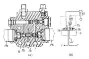
Specifically, a
またここでは、前記リンクアーム42の後端部を二股状に分岐する形状とし、この分岐部に同一形状の長穴42aを開口する一方、前記ブレーキシリンダ36のピストン先端部に、左右両側部を中央部と比較して小径とした段差部45aを備え且つ側面視前後に偏平部を有するピン45(図中(B))を取り付ける構成となっている。そして、このピン45の偏平部を、前記シリンダ36を下方から前記リンクアーム42の分岐間に挿通した後、同ピン45を90度回転させて、前記段差部45aを長穴42aに係止させた状態で同シリンダ36を略水平状態に固定する。
In addition, here, the rear end portion of the
これより、前記ブレーキシリンダ36のピストン先端部をリンクアーム42の長穴42a内で摺動自在に連結することができ、前記ブレーキペダル20,20を踏み込んだ時に前記ブレーキシリンダ36へ過剰な負荷がかかるることが無くなり、耐久性を損なうことが無い。
As a result, the piston tip of the
またトラクタ1の車体後部には、作業機昇降用油圧シリンダ48を内装するシリンダケース49を備え、前記シリンダ48のピストン伸縮によりケース49左右に支持するリフトアーム50,50を上下回動する構成となっている。また、車体後部にはトップリンク51aと左右ロアリンク51b,51bとから成る三点リンク機構51を設け、同リンク機構51に前記作業機Rを連結する構成となっている。また前記左右一側のリフトアーム50とロアリンク51bとを固定ロッド52にて接続し、他側を作業機ローリング用油圧シリンダ8及びこのピストン伸縮長さを検出するストロークセンサ8sにて接続し、作業機Rの左右一側(図例では右側)を上下操作して作業機の左右ローリング姿勢を変更する構成となっている。また前記リフトアーム50の片側には、この回動基部にリフトアーム角センサ50sを設けている。
The
これにより、前記コントローラCでは、作業機昇降用レバー32の操作角度とリフトアーム50の設定角度とを一致させるように、作業機上昇用の比例圧力制御弁53のソレノイド53s、或いは作業機下降用制御弁54のソレノイド54sへ通電し作業機Rを昇降する構成となっている。また前記ワンタッチ式作業機昇降レバー16の上下操作によって同作業機Rを、作業位置と別途設定した上げ位置との間を一気に上昇、若しくは下降させる構成となっている。
Thus, in the controller C, the
また前記作業機ローリング制御装置では、図5と図6に示すように、ポンプPからの圧油を前記ローリング用油圧シリンダ8へ三位置切替制御弁59の切替操作により連通させる構成となっている。
Further, in the work implement rolling control device, as shown in FIGS. 5 and 6, the pressure oil from the pump P is communicated with the rolling
詳しくは、前記切替制御弁59のスプール59sの両側にシリンダ短縮用のソレノイド59aと伸長用のソレノイド59bとを備え、前記伸長用のソレノイド59bへ通電することにより、前記スプール59sを移動し、ポンプPからの圧油を前記シリンダ8へ送り込み、前記作業機Rの右側を下げる構成となっている。また前記短縮用のソレノイド59aへ通電することにより、前記スプール59sを移動し、ポンプPからの圧油を二つのチェック弁55a,55bを介して圧油を送り込み、作業機Rの右側を上げる構成となっている。また前記二つのチェック弁の内、回路上手側に備えたチェック弁55bは、伸長用のソレノイド59aへ通電したときに、排出油路の開度を保つリフトリクション機構を構成するチェック弁55bとなっており、前記ピストン伸長用のソレノイド59aへ通電が行なわれると、シリンダ8内の圧油はチェック弁55b及び制御弁59内のスプール59sに形成したオリフィス59oを介してタンクポートTへ落ちる構成となっている。
Specifically, a cylinder shortening
尚、図中符号Bはバルブの筐体を示し、前記切替制御弁59、チェック弁55a,55bを一体的に内装する構成となっている。
In the figure, symbol B indicates a valve housing, and the switching control valve 59 and the
そして、作業機ローリング制御では、前記ローリング制御モード設定器31が「自動水平モード」であるときには前記スロープセンサ2の検出値と前記ストロークセンサ8sの検出値が別途備えた傾き調整ダイヤル56の値を維持するべく前記ローリング用油圧シリンダ8のピストンを駆動する。
In the work machine rolling control, when the rolling control
また「傾斜モード」では前記スロープセンサ2の検出値から地表の傾きを演算し、前器作業機Rの傾きを地表と平行になるよう前記ローリング用油圧シリンダ8のピストンを伸縮駆動する。
In the “tilt mode”, the inclination of the ground surface is calculated from the detection value of the
また「平行モード」では、前記ローリング用油圧シリンダ8の長さを固定ロッド52の長さ、或いは前記傾き手動スイッチ57の設定長さを維持する様、ローリング用油圧シリンダ8のピストンを駆動する。
In the “parallel mode”, the piston of the rolling
次に、トラクタ1の制御系統について図7に基づいて説明する。
Next, the control system of the
前記トラクタ1のコントローラCは、ホストコントローラとなる前記作業機Rの昇降及びローリング制御を司る作業機制御用コントローラC1と、メータパネルM上の各種表示機器を制御するメータパネル用コントローラC2と、、走行用コントローラC3とから構成され、夫れ夫れ内部に各種センサや設定器の情報を処理するCPU、前記情報を一時記憶するRAM、各種制御プログラム等を記憶するEEPROM等を備えると共に、他のコントローラのセンサ情報を共有するべく、通信回線で接続する構成となっている。
The controller C of the
そして、作業機制御用コントローラC1の入力部には、ワンタッチ式作業機昇降レバー16基部の上げスイッチ16a及び下げスイッチ16bと、作業機昇降レバー28基部のポテンショメータ28sと、リフトアーム角センサ42s、ローリング制御モード設定器31と、傾き調整ダイヤル33と、手動傾き設定スイッチ57、スロープセンサ2、ストロークセンサ8s等を接続して設けている。
The input unit of the work machine control controller C1 includes a
また出力側には、前記リフトアーム42を上動させるべく作業機昇降用油圧シリンダ48へ圧油を送る比例流量制御弁53のソレノイド53sと、作業機昇降用油圧シリンダ48から圧油を排出させる比例流量制御弁54のソレノイド54sと、ローリング用油圧シリンダ8へ圧油を送る切替制御弁59のソレノイド59aと、ローリング用油圧シリンダ8から圧油を排出する前記切替制御弁59のソレノイド59bとを接続して設けている。
Further, on the output side, the pressure oil is discharged from the
以上のように構成したトラクタ1では、図8と図9に示すように、作業機ローリング制御が行われる。
In the
最初にトラクタ1の電源系をONすると、作業機用コントローラC1では、各種センサや設定器の接続状態を読み込み、センサの診断処理を行う。このセンサの診断処理では、前記作業機昇降レバー28基部のポテンショメータ28sやリフトアーム角センサ42sといった、トラクタ1に標準装備するセンサの検出値が予め設定した範囲を超えて、異常値を示す場合は、前記メータパネルMへ警告を表示する。
When the power supply system of the
一方、トラクタ1にオプション部品として装備するセンサ、例えば旋回制御装置を行う上で利用する前輪切角センサ37等が予め設定した範囲を超える場合は、警告を行わず旋回制御を行う処理だけをジャンプする。
On the other hand, if the sensor equipped as an optional part on the
また前記作業機用コントローラC1では、前記ローリング制御モード設定器31の設定状態を判定する。
The work machine controller C1 determines the setting state of the rolling control
そして前記制御モードの設定が「自動水平モード」であれば、前記スロープセンサ2の値を所定時間毎に取得し、この値に対して前記作業機Rが傾き調整ダイヤル33の設定傾きとなるよう、前記ローリング用油圧シリンダ8のピストンを伸長、或いは短縮し、作業機Rの角度を保持する構成となっている。
If the setting of the control mode is “automatic horizontal mode”, the value of the
また前記制御モードが「平行モード」であれば、前記傾き手動スイッチ57の設定操作に応じて前記ローリング用油圧シリンダ8の長さを変更し、以後、前記ローリング用油圧シリンダ8のピストンを設定し、以後外部から負荷が係ったり、内部圧油がリークしても前記シリンダ8の長さを一定に保つ構成となっている。
If the control mode is “parallel mode”, the length of the rolling
また前記制御モードが「傾斜モード」であれば、傾斜基準値演算処理で求められた傾斜基準値に基づいて作業機Rの傾きを地表と平行になるよう前記ローリング用油圧シリンダ8のピストンを伸長、或いは短縮し、作業機Rの角度を保持する構成となっている。
If the control mode is “inclination mode”, the piston of the rolling
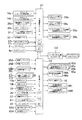
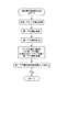
前記傾斜基準値演算処理では、図9と図10に示すように、前記作業機用コントローラC1が所定時間毎にスロープセンサ2の検出値(データサンプル値)を取得し、最初にスロープセンサ2の平均値(第一平均値Aven)を演算する。そして次に、この第一平均値と、新たに取得した最新のスロープセンサ2のセンサ値により第二平均値を演算し、この第二平均値を地表の傾斜基準値αとして前記RAMに設定する。またここでは前記センサ2の検出値の個数(サンプル数)を所定個数n個まで演算し、この第二平均値のn個のデータと、新たに取得した最新のスロープセンサ2の検出値のデータとを移動平均して地表の傾きを演算する構成となっている。
In the inclination reference value calculation process, as shown in FIGS. 9 and 10, the work machine controller C1 acquires the detection value (data sample value) of the
換言すると、n個以上溯った過去の第一平均値を消去し、新しく求めた第一平均値を、順次傾斜基準値αでサンプル値として演算に採用する。 In other words, the past first average value that has reached n or more is deleted, and the newly determined first average value is sequentially adopted as a sample value with the inclination reference value α.
これにより、最新の変化を傾斜基準値αの演算に最も大きく影響させて、作業機Rの「傾斜モード」に於けるローリング姿勢を迅速に対応させることができる。また、スロープセンサ2の検出値に異常値が生じても、時間が経過するほど異常検出値の影響を次第に小さくすることができ、例えば所定時間内の所定個数のセンサ検出値を単純に移動平均し、所定時間内はセンサ2の異常値が常に一定に影響する構成と比較して、正確な傾斜基準値αを求めることができ、ひいては作業機Rのローリング制御装置を正確に作動させることができる。
As a result, the latest change has the greatest influence on the calculation of the inclination reference value α, and the rolling posture in the “inclination mode” of the work machine R can be quickly handled. Further, even if an abnormal value occurs in the detection value of the
尚、この傾斜基準値αについては、この値をメータパネルMに表示したり、圃場マップを作成或いは表示するときのデータ値としても良い。また実際の制御の開始は、前記第一平均値(Aven)のサンプル個数がn個に至ったときに開始し、これまではパイロットランプを点滅して準備状態を表示する構成としても良い。また前記ローリング制御装置のモード設定器31を、図11に示すように、前記「水平モード」の代わりに前記手動傾き設定スイッチ57により作業機Rの傾きを任意に変更できる「手動モード」を有する構成としても良い。この際、モード設定器の設定ポジションは、「手動モード」を挟んで「傾斜モード」と「平行モード」を両側に夫れ夫れ配置する構成とし、モード切替時に、前記ローリング用油圧シリンダ8が不用意に駆動されることが無い様に図る。
In addition, about this inclination reference value (alpha), it is good also as a data value when this value is displayed on the meter panel M, or an agricultural field map is created or displayed. Further, the actual control may be started when the number of samples of the first average value (Aven) reaches n, and the preparation state may be displayed by blinking the pilot lamp until now. Further, as shown in FIG. 11, the
次に前記走行用コントローラC3の構成と、同コントローラC3が行う各種制御装置について説明する。 Next, the configuration of the travel controller C3 and various control devices performed by the controller C3 will be described.
走行用コントローラC3は、この入力部に変速レバー25の把持部の変速アップスイッチ25Aとダウンスイッチ25B、レバー基部の副変速位置センサ26L,26M,26H1,26H2、ミッションケース内部に備えた主変速位置センサ27a,27b…、前進スイッチ15a及び後進スイッチ15b、旋回制御入切スイッチ29、ブレーキ圧設定器30、車両の旋回操作を検出するセンサとなる前輪切角センサ37、アクセル制御入切スイッチ61、負荷制御入切スイッチ62a、負荷設定スイッチ62bを接続して設けている。
The travel controller C3 includes a shift up switch 25A and a
また出力部には、主変速装置の変速位置切替用のアクチュエータを駆動する制御弁のソレノイド65a,65b…、前後進切替装置の前後進切替位置を変更する制御弁のソレノイド66a,66b、アクセル位置を増減操作するアクセル調整モータ18、左右夫れ夫れの後輪を制動する前記ブレーキシリンダ36,36を駆動する比例流量制御弁のソレノイド66L,66Rを接続して設けている。
Further, the output section includes
そして以上のように構成した走行用コントローラC3では、アクセル制御入切スイッチ61が入のときアクセル制御を作動させる。
The travel controller C3 configured as described above activates the accelerator control when the accelerator control on / off
詳しくは、前記ワンタッチ式作業機昇降レバー16基部の上昇スイッチ16aのON操作や、昇降レバー28基部のポテンショメータ28sにより作業機Rの上昇操作を監視し、この操作を検出した時には、作業機Rの負荷が軽減したと想定し、前記アクセル調整モータ18へ通電しアクセル位置を、エンジン低回転側へ変更する。また前記作業機Rを下降操作した際には前記アクセル位置を復帰させる。
Specifically, when the operation of the work machine R is monitored by the ON operation of the
また前記アクセル制御では、前記変速レバー25をL,M,H1位置、即ち作業を想定した位置間でレバーを切替操作する間は作動しつづける構成とし、変速レバー25が路上走行領域H2に操作すると、作動を切りとして、同制御入切スイッチ61が再度入り設定されたときに同制御を作動する構成となっている。
In the accelerator control, the
尚、前記アクセル制御は、作業機Rの上昇操作を検出して作動する構成としたが、これをリフトアーム50側、即ち作業機Rの上昇駆動を検出する構成としても良い。また、作業機の上昇操作または上昇駆動に加えて前記後進スイッチ15bによりトラクタ1の後進操作を検出し、この時アクセル位置を低回転側に変更する構成としても良い。
In addition, although the said accelerator control was set as the structure which detects the raising operation of the working machine R, it is good also as a structure which detects the raising drive of the
また前記負荷制御では、前記エンジン回転センサ22によりトラクタ1に係る負荷状態を監視しながら、一定速度で走行する制御であり、前記負荷設定スイッチ62bを押込むと、この時点での速度Vを基準とし、このV+αの速度を上限として、前記コントローラC3が変速位置及びアクセル位置を上下操作して車両を定速走行する構成となっている。
In the load control, the
これにより、作業に適した負荷状態と車速を、オペレータ自ら決定し、安定した低速走行を行うことができる。 As a result, the load state and the vehicle speed suitable for the work can be determined by the operator himself and stable low-speed traveling can be performed.
1 トラクタ
2 スロープセンサ
C コントローラ
E エンジン
R ロータリ作業機
1
Claims (2)
Priority Applications (1)
| Application Number | Priority Date | Filing Date | Title |
|---|---|---|---|
| JP2004110186A JP4501504B2 (en) | 2004-04-02 | 2004-04-02 | Agricultural tractor |
Applications Claiming Priority (1)
| Application Number | Priority Date | Filing Date | Title |
|---|---|---|---|
| JP2004110186A JP4501504B2 (en) | 2004-04-02 | 2004-04-02 | Agricultural tractor |
Publications (2)
| Publication Number | Publication Date |
|---|---|
| JP2005287455A true JP2005287455A (en) | 2005-10-20 |
| JP4501504B2 JP4501504B2 (en) | 2010-07-14 |
Family
ID=35321103
Family Applications (1)
| Application Number | Title | Priority Date | Filing Date |
|---|---|---|---|
| JP2004110186A Expired - Fee Related JP4501504B2 (en) | 2004-04-02 | 2004-04-02 | Agricultural tractor |
Country Status (1)
| Country | Link |
|---|---|
| JP (1) | JP4501504B2 (en) |
Cited By (1)
| Publication number | Priority date | Publication date | Assignee | Title |
|---|---|---|---|---|
| JP2010017115A (en) * | 2008-07-09 | 2010-01-28 | Matsuyama Plow Mfg Co Ltd | Agriculture implement |
Citations (2)
| Publication number | Priority date | Publication date | Assignee | Title |
|---|---|---|---|---|
| JPH0252507U (en) * | 1988-10-04 | 1990-04-16 | ||
| JPH11253005A (en) * | 1998-03-09 | 1999-09-21 | Iseki & Co Ltd | Rolling control device for agricultural machinery |
-
2004
- 2004-04-02 JP JP2004110186A patent/JP4501504B2/en not_active Expired - Fee Related
Patent Citations (2)
| Publication number | Priority date | Publication date | Assignee | Title |
|---|---|---|---|---|
| JPH0252507U (en) * | 1988-10-04 | 1990-04-16 | ||
| JPH11253005A (en) * | 1998-03-09 | 1999-09-21 | Iseki & Co Ltd | Rolling control device for agricultural machinery |
Cited By (1)
| Publication number | Priority date | Publication date | Assignee | Title |
|---|---|---|---|---|
| JP2010017115A (en) * | 2008-07-09 | 2010-01-28 | Matsuyama Plow Mfg Co Ltd | Agriculture implement |
Also Published As
| Publication number | Publication date |
|---|---|
| JP4501504B2 (en) | 2010-07-14 |
Similar Documents
| Publication | Publication Date | Title |
|---|---|---|
| JP5662647B2 (en) | Rice transplanter | |
| JP2009040409A5 (en) | ||
| JP4501504B2 (en) | Agricultural tractor | |
| JP4300723B2 (en) | Tractor | |
| JP4967367B2 (en) | Traveling vehicle | |
| JP3876498B2 (en) | Turning control device for work vehicle | |
| JP7130598B2 (en) | work vehicle | |
| JP4525194B2 (en) | Tractor | |
| JP3918223B2 (en) | Steering control device for tractor | |
| JP4984393B2 (en) | Work vehicle | |
| JP2008037411A (en) | Tractor operating device | |
| JP6897542B2 (en) | Work vehicle | |
| US11505922B2 (en) | Working machine | |
| JPH09149705A (en) | Work machine | |
| JPH0522023Y2 (en) | ||
| JP3687190B2 (en) | Power vehicle turning control device | |
| JP2006194313A5 (en) | ||
| JP2000240787A (en) | Moving agricultural machine | |
| JP2008111561A (en) | Work vehicle | |
| JP4161560B2 (en) | Shift control device for work vehicle | |
| JP2024043641A (en) | work vehicle | |
| JP2024093641A (en) | Working machine, braking system for working machine, and method for controlling working machine | |
| JP4207322B2 (en) | Brake control device for work vehicle | |
| JP2003134903A (en) | Work vehicle forward / backward switching operation device | |
| JP2006329235A (en) | Traveling vehicle |
Legal Events
| Date | Code | Title | Description |
|---|---|---|---|
| A621 | Written request for application examination |
Free format text: JAPANESE INTERMEDIATE CODE: A621 Effective date: 20070130 |
|
| A977 | Report on retrieval |
Free format text: JAPANESE INTERMEDIATE CODE: A971007 Effective date: 20081015 |
|
| A131 | Notification of reasons for refusal |
Free format text: JAPANESE INTERMEDIATE CODE: A131 Effective date: 20081125 |
|
| A521 | Written amendment |
Free format text: JAPANESE INTERMEDIATE CODE: A523 Effective date: 20090126 |
|
| A131 | Notification of reasons for refusal |
Free format text: JAPANESE INTERMEDIATE CODE: A131 Effective date: 20090811 |
|
| A521 | Written amendment |
Free format text: JAPANESE INTERMEDIATE CODE: A523 Effective date: 20091008 |
|
| TRDD | Decision of grant or rejection written | ||
| A01 | Written decision to grant a patent or to grant a registration (utility model) |
Free format text: JAPANESE INTERMEDIATE CODE: A01 Effective date: 20100330 |
|
| A01 | Written decision to grant a patent or to grant a registration (utility model) |
Free format text: JAPANESE INTERMEDIATE CODE: A01 |
|
| A61 | First payment of annual fees (during grant procedure) |
Free format text: JAPANESE INTERMEDIATE CODE: A61 Effective date: 20100412 |
|
| R150 | Certificate of patent or registration of utility model |
Ref document number: 4501504 Country of ref document: JP Free format text: JAPANESE INTERMEDIATE CODE: R150 Free format text: JAPANESE INTERMEDIATE CODE: R150 |
|
| FPAY | Renewal fee payment (event date is renewal date of database) |
Free format text: PAYMENT UNTIL: 20130430 Year of fee payment: 3 |
|
| FPAY | Renewal fee payment (event date is renewal date of database) |
Free format text: PAYMENT UNTIL: 20130430 Year of fee payment: 3 |
|
| LAPS | Cancellation because of no payment of annual fees |