JP2005287461A - Supplying and discharging robot and automatic culture apparatus - Google Patents
Supplying and discharging robot and automatic culture apparatus Download PDFInfo
- Publication number
- JP2005287461A JP2005287461A JP2004111286A JP2004111286A JP2005287461A JP 2005287461 A JP2005287461 A JP 2005287461A JP 2004111286 A JP2004111286 A JP 2004111286A JP 2004111286 A JP2004111286 A JP 2004111286A JP 2005287461 A JP2005287461 A JP 2005287461A
- Authority
- JP
- Japan
- Prior art keywords
- tip
- culture
- robot
- air layer
- chip
- Prior art date
- Legal status (The legal status is an assumption and is not a legal conclusion. Google has not performed a legal analysis and makes no representation as to the accuracy of the status listed.)
- Withdrawn
Links
- 238000007599 discharging Methods 0.000 title abstract description 4
- 239000007788 liquid Substances 0.000 claims abstract description 64
- 238000003384 imaging method Methods 0.000 claims description 16
- 239000001963 growth medium Substances 0.000 claims description 9
- 238000012545 processing Methods 0.000 claims description 9
- 238000010899 nucleation Methods 0.000 claims description 7
- 230000032258 transport Effects 0.000 claims description 7
- 239000000126 substance Substances 0.000 claims description 6
- 238000011109 contamination Methods 0.000 abstract description 3
- 210000004027 cell Anatomy 0.000 description 33
- 230000007246 mechanism Effects 0.000 description 33
- 239000003153 chemical reaction reagent Substances 0.000 description 31
- 238000005192 partition Methods 0.000 description 27
- 239000002609 medium Substances 0.000 description 26
- 210000001185 bone marrow Anatomy 0.000 description 17
- 239000000428 dust Substances 0.000 description 16
- 239000012530 fluid Substances 0.000 description 16
- 238000011282 treatment Methods 0.000 description 16
- 210000002901 mesenchymal stem cell Anatomy 0.000 description 15
- 238000012546 transfer Methods 0.000 description 13
- 239000003219 hemolytic agent Substances 0.000 description 12
- 239000002699 waste material Substances 0.000 description 12
- 238000003860 storage Methods 0.000 description 10
- 239000011259 mixed solution Substances 0.000 description 9
- 210000002966 serum Anatomy 0.000 description 8
- 239000006285 cell suspension Substances 0.000 description 7
- 230000003749 cleanliness Effects 0.000 description 6
- 238000000034 method Methods 0.000 description 6
- 230000008569 process Effects 0.000 description 6
- 210000001519 tissue Anatomy 0.000 description 6
- 230000003028 elevating effect Effects 0.000 description 5
- 238000000605 extraction Methods 0.000 description 5
- 238000003780 insertion Methods 0.000 description 5
- 230000037431 insertion Effects 0.000 description 5
- 239000000463 material Substances 0.000 description 5
- 239000006144 Dulbecco’s modified Eagle's medium Substances 0.000 description 4
- LOKCTEFSRHRXRJ-UHFFFAOYSA-I dipotassium trisodium dihydrogen phosphate hydrogen phosphate dichloride Chemical compound P(=O)(O)(O)[O-].[K+].P(=O)(O)([O-])[O-].[Na+].[Na+].[Cl-].[K+].[Cl-].[Na+] LOKCTEFSRHRXRJ-UHFFFAOYSA-I 0.000 description 4
- 238000001035 drying Methods 0.000 description 4
- 210000003743 erythrocyte Anatomy 0.000 description 4
- 239000002953 phosphate buffered saline Substances 0.000 description 4
- 206010018910 Haemolysis Diseases 0.000 description 3
- 102000004142 Trypsin Human genes 0.000 description 3
- 108090000631 Trypsin Proteins 0.000 description 3
- 239000003242 anti bacterial agent Substances 0.000 description 3
- 230000003115 biocidal effect Effects 0.000 description 3
- 238000011049 filling Methods 0.000 description 3
- 230000005484 gravity Effects 0.000 description 3
- 230000008588 hemolysis Effects 0.000 description 3
- 230000001965 increasing effect Effects 0.000 description 3
- 238000002347 injection Methods 0.000 description 3
- 239000007924 injection Substances 0.000 description 3
- 239000000243 solution Substances 0.000 description 3
- 239000012588 trypsin Substances 0.000 description 3
- VUDQSRFCCHQIIU-UHFFFAOYSA-N 1-(3,5-dichloro-2,6-dihydroxy-4-methoxyphenyl)hexan-1-one Chemical compound CCCCCC(=O)C1=C(O)C(Cl)=C(OC)C(Cl)=C1O VUDQSRFCCHQIIU-UHFFFAOYSA-N 0.000 description 2
- 108091003079 Bovine Serum Albumin Proteins 0.000 description 2
- 102000004127 Cytokines Human genes 0.000 description 2
- 108090000695 Cytokines Proteins 0.000 description 2
- 101000942967 Homo sapiens Leukemia inhibitory factor Proteins 0.000 description 2
- 102100032352 Leukemia inhibitory factor Human genes 0.000 description 2
- 229930182555 Penicillin Natural products 0.000 description 2
- JGSARLDLIJGVTE-MBNYWOFBSA-N Penicillin G Chemical compound N([C@H]1[C@H]2SC([C@@H](N2C1=O)C(O)=O)(C)C)C(=O)CC1=CC=CC=C1 JGSARLDLIJGVTE-MBNYWOFBSA-N 0.000 description 2
- 229940088710 antibiotic agent Drugs 0.000 description 2
- 229910000389 calcium phosphate Inorganic materials 0.000 description 2
- 239000001506 calcium phosphate Substances 0.000 description 2
- 235000011010 calcium phosphates Nutrition 0.000 description 2
- 239000000470 constituent Substances 0.000 description 2
- 238000012258 culturing Methods 0.000 description 2
- UREBDLICKHMUKA-CXSFZGCWSA-N dexamethasone Chemical compound C1CC2=CC(=O)C=C[C@]2(C)[C@]2(F)[C@@H]1[C@@H]1C[C@@H](C)[C@@](C(=O)CO)(O)[C@@]1(C)C[C@@H]2O UREBDLICKHMUKA-CXSFZGCWSA-N 0.000 description 2
- 229960003957 dexamethasone Drugs 0.000 description 2
- 239000000284 extract Substances 0.000 description 2
- 239000012091 fetal bovine serum Substances 0.000 description 2
- 239000003102 growth factor Substances 0.000 description 2
- 238000004519 manufacturing process Methods 0.000 description 2
- 239000000203 mixture Substances 0.000 description 2
- 229940049954 penicillin Drugs 0.000 description 2
- QORWJWZARLRLPR-UHFFFAOYSA-H tricalcium bis(phosphate) Chemical compound [Ca+2].[Ca+2].[Ca+2].[O-]P([O-])([O-])=O.[O-]P([O-])([O-])=O QORWJWZARLRLPR-UHFFFAOYSA-H 0.000 description 2
- KIUKXJAPPMFGSW-DNGZLQJQSA-N (2S,3S,4S,5R,6R)-6-[(2S,3R,4R,5S,6R)-3-Acetamido-2-[(2S,3S,4R,5R,6R)-6-[(2R,3R,4R,5S,6R)-3-acetamido-2,5-dihydroxy-6-(hydroxymethyl)oxan-4-yl]oxy-2-carboxy-4,5-dihydroxyoxan-3-yl]oxy-5-hydroxy-6-(hydroxymethyl)oxan-4-yl]oxy-3,4,5-trihydroxyoxane-2-carboxylic acid Chemical compound CC(=O)N[C@H]1[C@H](O)O[C@H](CO)[C@@H](O)[C@@H]1O[C@H]1[C@H](O)[C@@H](O)[C@H](O[C@H]2[C@@H]([C@@H](O[C@H]3[C@@H]([C@@H](O)[C@H](O)[C@H](O3)C(O)=O)O)[C@H](O)[C@@H](CO)O2)NC(C)=O)[C@@H](C(O)=O)O1 KIUKXJAPPMFGSW-DNGZLQJQSA-N 0.000 description 1
- 102000008186 Collagen Human genes 0.000 description 1
- 108010035532 Collagen Proteins 0.000 description 1
- 102000035195 Peptidases Human genes 0.000 description 1
- 108091005804 Peptidases Proteins 0.000 description 1
- 229920000954 Polyglycolide Polymers 0.000 description 1
- 239000004098 Tetracycline Substances 0.000 description 1
- RTAQQCXQSZGOHL-UHFFFAOYSA-N Titanium Chemical compound [Ti] RTAQQCXQSZGOHL-UHFFFAOYSA-N 0.000 description 1
- 102000004887 Transforming Growth Factor beta Human genes 0.000 description 1
- 108090001012 Transforming Growth Factor beta Proteins 0.000 description 1
- 102000005789 Vascular Endothelial Growth Factors Human genes 0.000 description 1
- 108010019530 Vascular Endothelial Growth Factors Proteins 0.000 description 1
- 229940126575 aminoglycoside Drugs 0.000 description 1
- 230000008901 benefit Effects 0.000 description 1
- 210000004369 blood Anatomy 0.000 description 1
- 239000008280 blood Substances 0.000 description 1
- 210000001124 body fluid Anatomy 0.000 description 1
- 239000010839 body fluid Substances 0.000 description 1
- 210000000170 cell membrane Anatomy 0.000 description 1
- 230000004663 cell proliferation Effects 0.000 description 1
- 150000001782 cephems Chemical class 0.000 description 1
- 239000000919 ceramic Substances 0.000 description 1
- 230000008859 change Effects 0.000 description 1
- 239000003795 chemical substances by application Substances 0.000 description 1
- 238000004140 cleaning Methods 0.000 description 1
- 229920001436 collagen Polymers 0.000 description 1
- 230000007797 corrosion Effects 0.000 description 1
- 238000005260 corrosion Methods 0.000 description 1
- 230000007547 defect Effects 0.000 description 1
- 238000012217 deletion Methods 0.000 description 1
- 230000037430 deletion Effects 0.000 description 1
- 230000002542 deteriorative effect Effects 0.000 description 1
- 238000010586 diagram Methods 0.000 description 1
- 230000000694 effects Effects 0.000 description 1
- 229940011871 estrogen Drugs 0.000 description 1
- 239000000262 estrogen Substances 0.000 description 1
- 239000010419 fine particle Substances 0.000 description 1
- 229960000308 fosfomycin Drugs 0.000 description 1
- YMDXZJFXQJVXBF-STHAYSLISA-N fosfomycin Chemical compound C[C@@H]1O[C@@H]1P(O)(O)=O YMDXZJFXQJVXBF-STHAYSLISA-N 0.000 description 1
- 230000012447 hatching Effects 0.000 description 1
- 230000002949 hemolytic effect Effects 0.000 description 1
- 229940088597 hormone Drugs 0.000 description 1
- 239000005556 hormone Substances 0.000 description 1
- 229920002674 hyaluronan Polymers 0.000 description 1
- 229960003160 hyaluronic acid Drugs 0.000 description 1
- 230000006872 improvement Effects 0.000 description 1
- 238000009434 installation Methods 0.000 description 1
- 210000000265 leukocyte Anatomy 0.000 description 1
- 238000011068 loading method Methods 0.000 description 1
- 239000003120 macrolide antibiotic agent Substances 0.000 description 1
- 229910052751 metal Inorganic materials 0.000 description 1
- 239000002184 metal Substances 0.000 description 1
- 235000015097 nutrients Nutrition 0.000 description 1
- 230000000149 penetrating effect Effects 0.000 description 1
- 229920000747 poly(lactic acid) Polymers 0.000 description 1
- 239000004633 polyglycolic acid Substances 0.000 description 1
- 239000004626 polylactic acid Substances 0.000 description 1
- 230000035755 proliferation Effects 0.000 description 1
- LISFMEBWQUVKPJ-UHFFFAOYSA-N quinolin-2-ol Chemical compound C1=CC=C2NC(=O)C=CC2=C1 LISFMEBWQUVKPJ-UHFFFAOYSA-N 0.000 description 1
- 238000011084 recovery Methods 0.000 description 1
- 238000007665 sagging Methods 0.000 description 1
- 238000000926 separation method Methods 0.000 description 1
- -1 serum Substances 0.000 description 1
- 210000000130 stem cell Anatomy 0.000 description 1
- 238000003756 stirring Methods 0.000 description 1
- 239000006228 supernatant Substances 0.000 description 1
- 239000013589 supplement Substances 0.000 description 1
- 229960002180 tetracycline Drugs 0.000 description 1
- 229930101283 tetracycline Natural products 0.000 description 1
- 235000019364 tetracycline Nutrition 0.000 description 1
- 150000003522 tetracyclines Chemical class 0.000 description 1
- ZRKFYGHZFMAOKI-QMGMOQQFSA-N tgfbeta Chemical compound C([C@H](NC(=O)[C@H](C(C)C)NC(=O)CNC(=O)[C@H](CCC(O)=O)NC(=O)[C@H](CCCNC(N)=N)NC(=O)[C@H](CC(N)=O)NC(=O)[C@H](CC(C)C)NC(=O)[C@H]([C@@H](C)O)NC(=O)[C@H](CCC(O)=O)NC(=O)[C@H]([C@@H](C)O)NC(=O)[C@H](CC(C)C)NC(=O)CNC(=O)[C@H](C)NC(=O)[C@H](CO)NC(=O)[C@H](CCC(N)=O)NC(=O)[C@@H](NC(=O)[C@H](C)NC(=O)[C@H](C)NC(=O)[C@@H](NC(=O)[C@H](CC(C)C)NC(=O)[C@@H](N)CCSC)C(C)C)[C@@H](C)CC)C(=O)N[C@@H]([C@@H](C)O)C(=O)N[C@@H](C(C)C)C(=O)N[C@@H](CC=1C=CC=CC=1)C(=O)N[C@@H](C)C(=O)N1[C@@H](CCC1)C(=O)N[C@@H]([C@@H](C)O)C(=O)N[C@@H](CC(N)=O)C(=O)N[C@@H](CCC(O)=O)C(=O)N[C@@H](C)C(=O)N[C@@H](CC=1C=CC=CC=1)C(=O)N[C@@H](CCCNC(N)=N)C(=O)N[C@@H](C)C(=O)N[C@@H](CC(C)C)C(=O)N1[C@@H](CCC1)C(=O)N1[C@@H](CCC1)C(=O)N[C@@H](CCCNC(N)=N)C(=O)N[C@@H](CCC(O)=O)C(=O)N[C@@H](CCCNC(N)=N)C(=O)N[C@@H](CO)C(=O)N[C@@H](CCCNC(N)=N)C(=O)N[C@@H](CC(C)C)C(=O)N[C@@H](CC(C)C)C(O)=O)C1=CC=C(O)C=C1 ZRKFYGHZFMAOKI-QMGMOQQFSA-N 0.000 description 1
- 239000010936 titanium Substances 0.000 description 1
- 229910052719 titanium Inorganic materials 0.000 description 1
- 235000013343 vitamin Nutrition 0.000 description 1
- 239000011782 vitamin Substances 0.000 description 1
- 229940088594 vitamin Drugs 0.000 description 1
- 229930003231 vitamin Natural products 0.000 description 1
- 150000003722 vitamin derivatives Chemical class 0.000 description 1
Images




Landscapes
- Apparatus Associated With Microorganisms And Enzymes (AREA)
Abstract
Description
この発明は、給排ロボットおよび自動培養装置に関するものである。 The present invention relates to a supply / discharge robot and an automatic culture apparatus.
従来の自動培養装置としては、複数の培養容器を収納可能な固定式の収納棚と、水平・昇降・回転移動可能な搬送手段とを備えたものが知られている(例えば、特許文献1参照。)。
この自動培養装置は、培養室内に配置された収納棚に、鉛直方向に並ぶ複数の小部屋を備え、各小部屋の中に培養容器を1つずつ収容して培養を行い、培養途中あるいは培養終了時に搬送手段を作動させて、小部屋から1つずつ培養容器を取り出し、あるいは、小部屋へ培養容器を収容するよう構成されている。そして、培養室から取り出された培養容器に対しては、培養室の外部において蓋が開けられて内部に培地や薬液等が供給されるようになっている。
This automatic culture apparatus includes a plurality of small rooms arranged in a vertical direction on a storage shelf arranged in a culture chamber, and accommodates one culture container in each small room for culturing, either in the middle of culture or in culture At the end, the conveying means is operated to take out the culture containers one by one from the small room, or to accommodate the culture containers in the small room. And with respect to the culture container taken out from the culture chamber, a lid is opened outside the culture chamber, and a culture medium, a chemical solution, or the like is supplied to the inside.
しかしながら、上記特許文献1に示された自動培養装置では、給排ロボットが細胞等を含んだ検体をチップ内に吸引し、吸引した検体を搬送して培養容器内に数点に分けて播種する際に、チップの先端から検体の液だれが生じ、自動培養装置の底面に付着することが考えられる。そして、底面に付着した検体や、検体を含む培地等は乾燥することにより粉塵となって浮遊することが考えられる。この場合において、1種類の検体のみを取り扱う場合は問題ではないが、多数の検体を取り扱う場合においては、各検体の培養処理ごとに自動培養装置の底面を清掃しなければ、自動培養装置内に舞い上がった粉塵が他の検体を収容する容器内に混入する不都合が考えられる。
また、分注ロボットが培養トレイ内の培地の排出を行ったり培養トレイ内に新たな培地の注入を行う際に、チップの先端から培地の液だれが生じ、装置内を汚染してしまうおそれもある。
However, in the automatic culture apparatus disclosed in
In addition, when the dispensing robot discharges the medium in the culture tray or injects a new medium into the culture tray, the medium may drip from the tip of the chip and may contaminate the inside of the device. is there.
この発明は、上記の事情に鑑みてなされたもので、チップ先端からの液だれを防止して、装置内の汚染を防止することのできる給排ロボットおよびこれを備えた自動培養装置を提供することを目的とする。 The present invention has been made in view of the above circumstances, and provides a supply / discharge robot capable of preventing dripping from the tip of the chip and preventing contamination in the apparatus, and an automatic culture apparatus equipped with the same. For the purpose.
上記目的を達成するために、この発明は、以下の手段を提供する。
この発明は、細胞等の検体を吸引するチップを先端に備え、チップ内に吸引された検体を搬送して培養容器内に播種する給排ロボットであって、検体の吸引終了時、前記チップの先端に空気層が形成されるように、前記検体を吸引する液送動力装置が設けられている給排ロボットを提供する。
この発明によれば、検体の吸引終了時に、液送動力装置によりチップの先端に空気層が形成されるようになっているので、チップの先端部外表面に付着した検体が、チップの先端部外表面に沿って下方(すなわち、チップの先端)に移動してきたとしても、検体が空気層の部分に入り込んでチップの先端における検体による液玉の発生が防止され、吸引された検体がチップの先端から下方に垂れてしまうことが防止されるとともに、検体が乾燥して形成される粉塵等の、蓋の開いた培養容器内への混入が確実に防止されることとなる。
In order to achieve the above object, the present invention provides the following means.
The present invention is a supply / discharge robot having a tip for aspirating a specimen such as a cell at the tip, transporting the specimen aspirated into the chip and seeding it in a culture container, and at the end of aspiration of the specimen, Provided is a supply / discharge robot provided with a liquid feeding power device for sucking the specimen so that an air layer is formed at the tip.
According to the present invention, since the air layer is formed at the tip of the chip by the liquid feeding power device when the sample is aspirated, the sample attached to the outer surface of the tip of the chip is Even if the sample moves downward along the outer surface (that is, the tip of the chip), the sample enters the air layer portion, and the generation of liquid droplets by the sample at the tip of the chip is prevented. While preventing the sample from dripping downward from the tip, it is possible to reliably prevent dust or the like formed by drying the specimen from entering the culture vessel with the lid open.
また、この発明は、前記空気層を撮像する撮像手段と、該撮像手段により撮像された画像を処理して前記空気層の体積を算出するとともに、該空気層の体積を考慮した播種情報を前記液送動力装置に出力する制御装置とを具備している給排ロボットを提供する。
この発明によれば、チップの先端に形成された空気層が、撮像手段により撮像されるとともに、撮像手段により撮像された画像が制御装置に送られ、制御装置により空気層の体積が算出されて、制御装置では、この空気層の体積を考慮した播種情報が液送動力装置に出力されるようになっているので、検体を培養容器内に数点に分けて播種する際に、均等に播種されることとなる。
The present invention also provides an imaging unit that images the air layer, calculates the volume of the air layer by processing an image captured by the imaging unit, and includes the seeding information in consideration of the volume of the air layer. Provided is a supply / discharge robot including a control device that outputs to a liquid feeding power device.
According to the present invention, the air layer formed at the tip of the chip is imaged by the imaging unit, the image captured by the imaging unit is sent to the control device, and the volume of the air layer is calculated by the control device. In the control device, the seeding information considering the volume of the air layer is output to the liquid feed power device, so when the sample is seeded in several points in the culture vessel, seeding is performed evenly. Will be.
さらに、この発明は、培地または薬液等の液体を吸引するチップを先端に備え、チップ内に吸引された液体を搬送して分注する分注ロボットであって、液体の吸引終了時、前記チップの先端に空気層が形成されるように、前記液体を吸引する液送動力装置が設けられている分注ロボットを提供する。
この発明によれば、液体の吸引終了時に、液送動力装置によりチップの先端に空気層が形成されるようになっているので、チップの先端部外表面に付着した液体が、チップの先端部外表面に沿って下方(すなわち、チップの先端)に移動してきたとしても、液体が空気層の部分に入り込んでチップの先端における液体による液玉の発生が防止され、吸引された液体がチップの先端から下方に垂れてしまうことが防止されるとともに、装置内の汚染が防止されて、装置内がクリーンな状態に保たれることとなる。
Furthermore, the present invention is a dispensing robot that has a tip for sucking a liquid such as a culture medium or a chemical solution at the tip, and that transports and dispenses the liquid sucked into the tip, and when the suction of the liquid ends, the tip A dispensing robot provided with a liquid feeding power device for sucking the liquid so that an air layer is formed at the tip of the liquid is provided.
According to the present invention, when the liquid suction is finished, the liquid feeding power device forms an air layer at the tip of the chip, so that the liquid adhering to the outer surface of the tip of the chip is transferred to the tip of the chip. Even if it moves downward along the outer surface (that is, the tip of the chip), the liquid enters the air layer portion, and the generation of liquid balls due to the liquid at the tip of the chip is prevented. It is possible to prevent the apparatus from sagging downward from the tip and to prevent contamination in the apparatus, thereby keeping the apparatus in a clean state.
さらにまた、この発明は、前記空気層を撮像する撮像手段と、該撮像手段により撮像された画像を処理して前記空気層の体積を算出するとともに、該空気層の体積を考慮した分注情報を前記液送動力装置に出力する制御装置とを具備している分注ロボットを提供する。
この発明によれば、チップの先端に形成された空気層が、撮像手段により撮像されるとともに、撮像手段により撮像された画像が制御装置に送られ、制御装置により空気層の体積が算出されて、制御装置では、この空気層の体積を考慮した分注情報が液送動力装置に出力されるようになっているので、チップ内から分注される液体の量を精度よく把握することができる。
Furthermore, the present invention provides an imaging unit that images the air layer, and calculates the volume of the air layer by processing an image captured by the imaging unit, and dispensing information that considers the volume of the air layer A dispensing robot is provided that includes a control device that outputs to the liquid feeding power device.
According to the present invention, the air layer formed at the tip of the chip is imaged by the imaging unit, the image captured by the imaging unit is sent to the control device, and the volume of the air layer is calculated by the control device. In the control device, since the dispensing information considering the volume of the air layer is output to the liquid feeding power device, it is possible to accurately grasp the amount of liquid dispensed from within the chip. .
この発明によれば、チップ内に検体を吸引する際、液送動力装置によりチップの先端に空気層ができるように当該チップが取り付けられた電動ピペットが駆動制御されるようになっているので、電動ピペットにより吸引された検体がチップの先端から下方に垂れてしまうことを防止することができるとともに、検体が乾燥して形成される粉塵等の、蓋の開いた培養容器内への混入を確実に防止することができるという効果を奏する。 According to this invention, when the sample is aspirated into the tip, the electric pipette to which the tip is attached is driven and controlled so that an air layer is formed at the tip of the tip by the liquid feeding power device. The sample sucked by the electric pipette can be prevented from dripping down from the tip of the tip, and the dust that is formed by drying the sample is surely mixed into the open culture vessel. There is an effect that it can be prevented.
この発明の一実施形態に係る培養処理装置および自動培養装置について、図1〜図8を参照して説明する。
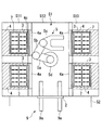
本実施形態に係る自動培養装置1は、図1に示されるように、外部から観察可能な透明な壁材により密閉され、シャッタ2を介して相互に連絡する第1空間S1と第2空間S2とを備えている。
A culture treatment apparatus and an automatic culture apparatus according to an embodiment of the present invention will be described with reference to FIGS.
As shown in FIG. 1, the
第1空間S1の両側空間S11,S13には、培養容器3を収容する培養室4が2個ずつ計4個配置され、中央空間S12には、培養容器3を移動するための搬送ロボット(搬送機構)5が備えられている。中央空間S12の上部には、中央空間S12内の空気を浄化するために清浄な下降気流を送る空気清浄部6が設けられている。
4個の培養室4は、それぞれ中央空間S12に向けて扉4aを配置することにより、横に並んだ2個ずつが相互に扉4aを対向させて、間隔をあけて配置されている。
A total of four
Each of the four
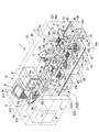
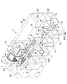
前記各培養室4は、図2および図3に示されるように、一側面に開口部4bを有し、該開口部4bを開閉可能な扉4aを備えている。開口部4bに向かって左右の側壁には、対応する高さ位置に複数のレール状のトレイ保持部材4cが設けられており、左右対となる各トレイ保持部材4cに掛け渡すようにして、トレイ7を上下方向に複数段収容できるようになっている。各培養室4内は、所定の培養条件、例えば、温度37±0.5℃、湿度100%およびCO2濃度5%等に維持されている。なお、トレイ保持部材4cはレール状に限定されず、トレイ7を出し入れ可能に支持することができれば任意の形態でよい。
As shown in FIGS. 2 and 3, each
各トレイ7には、複数個、例えば、10個の培養容器3を並べて載置できるようになっている。各培養容器3は、図4に示されるように、容器本体3aと、該容器本体3aの上面に設けられた蓋体3bとからなり、容器本体3aの左右の側面には、後述する第2空間内のハンドにより引っかけられる突起3cが設けられている。
A plurality of, for example, ten
各培養室4の下方には、図1に示されるように、未使用の培養容器3をトレイ7に搭載した状態で複数収容するストッカ8が配置されている。ストッカ8は、前記培養室4の扉とは反対側の第1空間S1の外部に向かう側面に開閉可能なドアを有している。該ドアは、ストッカ8の一側面全体を開放する大きさに形成されている。
Below each
前記搬送ロボット5は、4個の培養室4の間隔位置のほぼ中央に配置されている。該搬送ロボット5は、水平回転可能な第1アーム5aと、該第1アーム5aの先端に鉛直軸回りに回転可能に連結された第2アーム5bと、該第2アーム5bの先端に鉛直軸回りに回転可能に取り付けられ、それ自身は駆動部、伝導機構などの培養室内の環境を劣化させる機構を持たないハンド5cと、これら第1アーム5a、第2アーム5bおよびハンド5cを昇降可能な昇降機構5dとを備えている。これにより、搬送ロボット5は、4個の培養室4内の全てのトレイ7にアクセスするとともに、前記シャッタ2を跨いで第1空間S1と第2空間S2との間に配置されたコンベア9上にトレイ7を引き渡すことができる水平方向の動作範囲を有している。
The
前記コンベア9は、搬送ロボット5のハンド5cの幅寸法より大きな間隔をあけて左右に配置された2本の無端ベルト9aを備え、これら無端ベルト9aに掛け渡してトレイ7を載置できるようになっている。また、搬送ロボット5は、培養室4内の全てのトレイ7にアクセスするとともに、前記ストッカ8内の少なくとも最上段のトレイ7にアクセスできる垂直方向の動作範囲を有している。
なお、ベルト9aは無端ベルトに限られない。
The
The
前記ハンド5cは、トレイ7を載置可能に水平方向に延びる平坦な形状に形成されており、培養室4に収容されているトレイ7間の隙間に挿入可能な厚さ寸法に形成されている。そして、ハンド5cは、トレイ7間の隙間に挿入された状態から上昇させられることにより、2本の腕によってトレイ7を下方から押し上げてトレイ保持部材4cから取り上げるとともに、トレイ7を安定して保持できるようになっている。
The
培養処理装置30は、図1に示されるように、検体抽出装置50、給排ロボット10、遠心分離器11、分注ロボット13、チップ供給装置15、チップ回収部31、試薬等供給装置16、顕微鏡17、貯留タンク18、水平移動機構19および載置台21を備えている。
検体抽出装置50は、例えば、医療機関等で患者から採取された骨髄液を導入され、供給された骨髄液から間葉系幹細胞を多く含む検体を抽出する装置であって、導入された骨髄液を貯留する容器内に溶血剤を注入する溶血剤注入装置54と、溶血剤が注入された骨髄液を攪拌する給排ロボット10と、攪拌された骨髄液から間葉系幹細胞を多く含む検体を分離する遠心分離器11とにより構成されている。
As shown in FIG. 1, the
The
給排ロボット10は、シャッタ2が開かれた状態で第1空間S1からコンベア9によって搬送されてきたトレイ7上の培養容器3に対し、上記検体抽出装置50において抽出された細胞を供給し、あるいは、培地を供給、回収するようになっている。遠心分離機11は、培養容器3内の培地から細胞を分離するように構成されている。分注ロボット13は、血清や試薬等の種々の液体を分注するための電動ピペット12を備えた水平回転および昇降移動可能なロボットであって、第2空間S2内に4台設置されている。
The supply /
前記チップ供給装置15は、これら給排ロボット10および分注ロボット13の電動ピペット12先端に取り付ける使い捨て可能なチップ14を複数収容していて給排ロボット10および分注ロボット13の動作範囲内に提供するようになっている。前記チップ回収部31は、使用済みのチップ14を廃棄回収するようになっている。前記試薬等供給装置16は、血清や試薬等の種々の液体を複数の容器に貯留している。顕微鏡17は培養容器3内における細胞の様子を観察できるようになっている。貯留タンク18は、各試薬および培地交換等により廃棄される廃液をそれぞれ貯留するように複数設けられている。水平移動機構19は、前記コンベア9と各ロボット10,13との間で培養容器3を受け渡し可能とするように培養容器3を移動させるようになっている。前記載置台21は、水平移動機構19のスライダ20に取り付けられ、受け取った培養容器3を載置するように構成されている。
The
また、第2空間S2には、該第2空間S2内の空気を清浄化するために清浄な下降気流を形成する空気清浄機32が設けられている。
前記第2空間S2に構成された培養処理装置30は、その高さ方向の中間位置に配され第2空間S2内を上部空間S21と下部空間S22とに上下に区画する第1の区画壁33と、該第1の区画壁33により形成された下部空間S22内をさらに上下に区画する第2の区隔壁34とにより、上下方向に並ぶ3つの空間S21,S221,S222に区画されている。第1の区画壁33は、前記コンベア9の高さに配置され、その上方の上部空間S21内に、載置台21、給排ロボット10、分注ロボット13のアーム13a、顕微鏡17のXYテーブル17a以上の機構部等を配置している。これらの装置は、培養容器3の移動に必要な装置、および培養容器3の上部開口からアクセスすることが必要な装置だからである。なお、試薬等供給装置16の上面も第1の区画壁33の上面に露出しているが、これはチップ14の挿入口16cを上部空間S21に開口させるためである。
The second space S2 is provided with an
The
また、第1の区画壁33には、載置台21を上部空間S21において移動させるために、載置台21を下部空間S22内の水平移動機構19に連結するための長孔35、第1の区画壁33の下方の空間S221に配置されたチップ供給装置15からチップ14を取り出すための貫通孔36、使用済みのチップ14を廃棄するための廃棄口37が貫通形成されている。
さらに、第1の区画壁33には、その側壁30a,30bに沿って、上下に貫通する通気口38(図において斜線部で示す)が設けられている。
The
Further, the
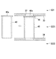
第1の区画壁33と第2の区画壁34との間の空間S221には、図6に示されるように、分注ロボット13の本体部分、チップ供給装置15、試薬等供給装置16、顕微鏡17のXYテーブル17a以下の部分、水平移動機構19および、チップ回収部31の廃棄口37と廃棄容器39とを接続するダクト40が備えられている。前記ダクト40は、図7に示されるように、例えば、その上端にフランジ部40aを備える構造とされ、第1の区画壁33の下部に設けたフック44に引っかけることで、第1の区画壁33と第2の区画壁34との間に着脱可能に設ければよい。第2の区画壁34の側壁30a,30b近傍には、該側壁30a,30bに沿って、上下に貫通する通気口43(図において斜線部で示す)が設けられている。
In the space S221 between the
さらに、第2の区画壁34の下方の空間S222には、図8に示されるように、遠心分離機11、貯留タンク18、廃棄容器39、および排気ファン41が配置されている。排気ファン41の出口にはHEPAフィルタのようなフィルタ42が設けられ、排気される空気を清浄にするようになっている。
Further, in the space S222 below the
前記給排ロボット10は、水平多関節型ロボットであって、例えば、図1に示す例では、2種類の電動ピペット10a,10bを備えるヘッド10cと、水平旋回可能な2つのアーム10d,10eと、アーム10eの先端に設けられヘッド10cを昇降させる昇降機構10fと、液送動力装置10h(図8参照)とを備えている。電動ピペット10aは、貯留タンク18からダクト10gを介して導かれた培地を供給し、あるいはピペッティング動作を行うようになっている。電動ピペット10bは、培養容器3内あるいは遠心容器内の不要な培地を吸引し、ダクト10gを介して他の貯留タンク18へ廃液として排出するようになっている。
液送動力装置10hは、電動ピペット10a,10b、ヘッド10c、アーム10d,10e、および昇降機構10fを駆動制御するものである。また、図8に示すように、この液送動力装置10hは制御装置51に接続されているとともに、制御装置51はカメラ(撮像手段)52に接続されている。
制御装置51は、カメラ52で捉えたチップ14の先端の状態、すなわち、チップ14の先端に形成された空気層Aを含んだ画像を処理して、この空気層Aの体積を算出するとともに、液送動力装置10hに空気層Aの体積を考慮した情報を出力するものである。
The supply /
The liquid
The
電動ピペット10aによるピペッティング動作は、前記溶血剤注入装置54により溶血剤を注入された骨髄液に対して行われるとともに、遠心分離機11により分離された細胞に対しても行われるようになっている。ピペッティング動作は、電動ピペット10aの先端にチップ供給装置15から供給されたチップ14を装着して、骨髄液と溶血剤との混合液(検体)、あるいは細胞と培地との混合液(検体)に対し、吸引および放出を10回〜20回繰り返す。これにより、混合液を均一に攪拌するようになっている。
The pipetting operation by the
また、給排ロボット10は、ピペッティング動作の後に、電動ピペット10aによって、遠心分離機11により分離された細胞と培地との混合液M(図8参照)を吸引し、載置台21上に搭載された培養容器3内に上部開口から供給するようになっている。
電動ピペット10aが、混合液Mを培養容器3内に数点に分けて均等に播種するため、チップ14内に混合液Mを吸引する際には、図8に示すように、液送動力装置10hによりチップ14の先端に空気層Aができるように電動ピペット10aが駆動制御されるようになっている。
このように、チップ14の先端に空気層Aを設けるようにすることにより、チップ14の先端部外表面に付着した混合液Mが、チップ14の先端部外表面に沿って下方(すなわち、チップ14の先端)に移動してきたとしても、混合液Mが空気層Aの部分に入り込んでチップ14の先端に混合液Mによる液玉の発生が防止されるので、電動ピペット10aにより吸引された混合液Mがチップ14の先端から下方(すなわち、第1の区画壁33の表面)に垂れてしまうことを防止することができる。
この空気層Aはカメラ52により撮像されるとともに、カメラ52により撮像された画像は制御装置51に送られ、制御装置51により空気層Aの体積が算出されるようになっている。また、制御装置51では、この空気層Aの体積を考慮した信号(播種情報)が液送動力装置10hに出力されるようになっており、これにより混合液Mが培養容器3内に数点に分けて播種する際に、均等に播種されるようになっている。
In addition, after the pipetting operation, the supply /
Since the
As described above, by providing the air layer A at the tip of the
The air layer A is imaged by the
一旦使用された使用済みのチップ14は、チップ回収部31において取り外され回収されるようになっている。したがって、給排ロボット10は、溶血剤注入装置54、載置台21、チップ供給装置15、チップ回収部31および遠心分離機11からの細胞供給装置(図示略)等の種々の装置をその動作範囲内に配置している。
The used
前記遠心分離機11は、ピペッティングにより混合された骨髄液と溶血剤との混合液を貯留した容器を受け取って低速回転させることにより、骨髄液内に含有されている間葉系幹細胞等の白血球をその他の体液から分離して沈下させるようになっている。また、遠心分離機11は、給排ロボット10から供給された細胞入り培地を低速回転させることにより培地内に浮遊していた比重の重い細胞を培地から分離して沈下させるようになっている。
The
前記分注ロボット13は、それぞれ、先端にチップ14を着脱可能に取り付ける電動ピペット12を備えた水平回転可能なアーム13aと、該アーム13aを昇降させる昇降機構13bとを備えている。分注ロボット13は、水平移動機構19によって搬送されて来た培養容器3内へ、培地や種々の試薬を供給するようになっている。したがって、分注ロボット13は、水平移動機構19上の載置台21、チップ供給装置15、チップ回収部31および試薬等供給装置16等の種々の装置をその動作範囲内に配置している。
Each of the dispensing
前記チップ供給装置15は、上方に開口した容器15a内に、電動ピペット10a,10b,12への取付口を上向きにして複数のチップ14を配列状態に収容しており、給排ロボット10や分注ロボット13が、新たなチップ14を必要とするときに、電動ピペット10a,10b,12を上方から挿入するだけで、電動ピペット10a,10b,12の先端にチップ14を取り付けるように構成されている。容器15aは、給排ロボット10や分注ロボット13による電動ピペット10a,10b,12の移動方向に対して交差する方向に往復移動させられるように移動機構15bに取り付けられている。また、分注ロボット13にチップ14を供給するチップ供給装置15には、移動機構15bによる移動方向とは直交する方向に容器15aを移動させる他の移動機構15cが備えられている。これにより、容器15a内の全てのチップ14に対して電動ピペット10a,10b,12がアクセスすることができるようになっている。
The
前記チップ回収部31は、廃棄容器39の入口に、チップ14を把持する把持装置(図示略)を備えていて、給排ロボット10や分注ロボット13において使用されたチップ14が把持装置に挿入されると、これを把持するようになっている。そして、この状態で給排ロボット10や分注ロボット13が電動ピペット10a,10b,12を移動させることにより、電動ピペット10a,10b,12先端から使用済みチップ14が取り外され、廃棄容器39内にダクト40を介して回収されるようになっている。廃棄容器39は、空間S222内に着脱可能に配置されており、必要に応じて交換可能となっている。
The
前記ダクト40および廃棄容器39の交換時には、培養処理装置30の側壁30a,30bに設けられた図示しないドアを開くことにより、培養処理装置30の外部からアクセスすることとすればよい。
When exchanging the
前記試薬等供給装置16は、例えば、図6に示されるように、円筒状のケーシング内部に、水平回転可能なテーブル16aを収容し、該テーブル16a上に、扇型の底面形状を有する筒状の試薬等容器16bを周方向に複数配列して搭載している。ケーシング内部は一定の温度に保冷されている。各試薬等容器16bには、種々の試薬等が貯留されている。例えば、細胞を培養するために必要な培地を構成するMEM(Minimal Essential Medium:最小必須培地)、DMEM(Dulbecco's Modified
Eagle Medium)、FBS(Fetal Bovine Serum:ウシ胎児血清)やヒト血清のような血清、培養容器3内の細胞を剥離させるトリプシンのような蛋白質分解酵素や、培養に際して細胞を成長させるサイトカインのような成長因子、細胞を分化させるデキサメタゾンのような分化誘導因子、ペニシリン系抗生物質のような抗生剤、エストロゲン等のホルモン剤や、ビタミン等の栄養剤が貯留されている。
For example, as shown in FIG. 6, the
Such as Eagle Medium), FBS (Fetal Bovine Serum) and serum such as human serum, proteolytic enzyme such as trypsin that peels off the cells in the
試薬等供給装置16のケーシングの上面には、分注ロボット13が電動ピペット12先端のチップ14を挿入する挿入口16cが設けられている。この挿入口16cは、前記分注ロボット13の動作範囲内に配置されている。また、各試薬等容器16bは、その上面に、前記挿入口16cに一致する位置に配置される開口部(図示略)を備えている。これにより、テーブル16aを回転させて試薬等容器16bの開口部をケーシングの挿入口16cの鉛直下方に配置することで、分注ロボット13が、電動ピペット12先端のチップ14を上方から試薬等容器16b内へ挿入して、内部に貯留されている試薬等を吸引することができるようになっている。試薬等供給装置16を2台設けているのは、検体に共通のトリプシンのような薬液と、検体に固有の血清のような液体とを分離して取り扱うようにしているためである。
An
前記顕微鏡17は、培養工程の途中、あるいは、培地交換の際に、培養容器3内の細胞の様子や増殖の程度を観察したり、細胞数を計数したりする場合等に使用されるようになっている。顕微鏡17のXYステージ17aや作動距離調整、倍率の変更等は全て遠隔操作により行うことができるように構成されている。第2空間S2の外方に向けて接眼レンズを配置しておくことにより、自動培養装置1の外部から培養容器3内の細胞の状態を観察できるようにしてもよい。
The
前記貯留タンク18は、例えば、全ての検体に共通して使用できるMEMやPBS(リン酸緩衝化食塩水)等を貯留しておき、必要に応じて試薬等供給装置16内の試薬等容器16b内に供給するようになっている。また、貯留タンク18には、廃液タンクとして、培地交換の際に排出される廃培地等を貯留するものもある。
The
前記水平移動機構19は、直線移動機構により水平方向に移動可能なスライダ20を備えている。スライダ20上には前記載置台21が搭載されており、載置台21に搭載された培養容器3を、コンベア9から分注ロボット13の動作範囲まで移動させることができるようになっている。
The
前記載置台21は、コンベア9上のトレイ7内から移載された培養容器3を搭載して保持する保持機構(図示略)を備えている。また、該培養容器3に振動を付与する加振装置(図示略)を備えていてもよい。加振装置は、例えば、培養容器3を所定の角度範囲で往復揺動させる装置の他、超音波振動を加える装置や、水平方向の振動を加える装置を採用してもよい。
本実施形態に係る自動培養装置1の各種装置には、図示しない制御装置が接続されている。制御装置は、各工程の順序や動作タイミング等を制御するとともに、動作履歴等を記録保存するようになっている。
The mounting table 21 includes a holding mechanism (not shown) for mounting and holding the
A control device (not shown) is connected to various devices of the
このように構成された本実施形態に係る培養処理装置30および自動培養装置1の作用について、以下に説明する。
本実施形態に係る自動培養装置1を用いて、間葉系幹細胞を培養するには、まず、患者から採取された骨髄液を容器に入れた状態で培養処理装置30内に導入し、検体抽出装置50に供給する。この工程は作業者が行ってもよいが、図示しないハンドリングロボットにより行ってもよい。
The operation of the
In order to culture mesenchymal stem cells using the
検体抽出装置50においては、溶血剤注入装置54の作動により、骨髄液に溶血剤が注入されて、給排ロボット10の電動ピペット10bに取り付けたチップ14の先端が、骨髄液と溶血剤とが混合された容器内に挿入され、電動ピペット10bの作動により、容器内の混合液が繰り返し吸引、放出される。これにより、骨髄液と溶血剤とが均一に混合されるので、この状態で、例えば、3〜7min程度放置することにより溶血処理を行う。
In the
溶血処理により、比重の大きな赤血球の細胞膜が破壊され、容器内の赤血球が除去されることになる。
その後、ハンドリングロボットの作動により、容器が遠心分離機11に投入される。そして、遠心分離機11が、例えば、800〜1300Gで3〜5min間作動させられることにより、骨髄液内の比重の重い間葉系幹細胞を含む細が沈降した状態に集められる。
Due to the hemolysis treatment, the cell membrane of red blood cells having a large specific gravity is destroyed, and the red blood cells in the container are removed.
Thereafter, the container is put into the
この状態で、再度ハンドリングロボットの作動により、容器が遠心分離機11外に取り出される。そして、給排ロボット10およびチップ供給装置15の作動により、電動ピペット10b先端に未使用のチップ14が取り付けられる。
すなわち、チップ供給装置15は移動機構15bを作動させることにより、未使用のチップ14を給排ロボット10の動作範囲内に配する。すると、給排ロボット10は、昇降機構10fを作動させることにより、ヘッド10cを下降させて、第1の区画壁33下方のチップ供給装置15から未使用のチップ14を受け取り、電動ピペット10bの先端に取り付ける。
In this state, the container is taken out of the
That is, the
この状態で、給排ロボット10を作動させて電動ピペット10bのチップ14の先端を容器内に挿入して吸引する。これにより、容器内の上澄み液が除去され、赤血球を含まない間葉系幹細胞を多く含む細胞が容器内に残される。
In this state, the supply /
次に、容器内に残った検体は、給排ロボット10により、培養容器3に投入される。投入に先立って、コンベア9の作動により、トレイ7に載せた10個の空の培養容器3が、第1空間S1から第2空間S2に差し出されている。トレイ7上の培養容器3の内の2個の培養容器3が、図示しない移載装置の作動により、載置台21上に載置される。そして、図示しない蓋体開閉装置の作動により、載置台21上の培養容器3の蓋体3bが開けられる。
Next, the specimen remaining in the container is put into the
この状態で、給排ロボット10を作動させて、電動ピペット10aから容器内に、貯留タンク18に貯留されているDMEMやPBS(リン酸緩衝化食塩水)等の培地構成液を、所定量供給する。電動ピペット10a先端のチップ14を容器内に挿入した状態に保持したまま、電動ピペット10aを作動させることにより、ピペッティングを行う。これにより、赤血球を含まず、間葉系幹細胞を多く含む細胞と培地構成液とが均一に混合された細胞懸濁液が構成されることになる。
In this state, the supply /
このようにして製造された細胞懸濁液は、電動ピペット10aを作動させることにより、チップ14内に吸引される。吸引された細胞懸濁液は、チップ14内に保持された状態で、給排ロボット10を作動させることにより、載置台21上の培養容器3内に上部開口から投入される。
The cell suspension thus produced is sucked into the
細胞懸濁液を培養容器3内に投入し終わると、給排ロボット10は、第1の区画壁33に形成された廃棄口37にチップ14を挿入して取り外し、チップ回収部31に回収させる。廃棄口37において取り外されたチップ14は、ダクト40を介して、最下位の空間S222に配置されている廃棄容器内に投入される。
When the cell suspension is completely put into the
次に、細胞懸濁液が投入された培養容器3は、水平移動機構19を作動させることにより、載置台21ごと水平移動させられ、各分注ロボット13の動作範囲内に配置される。分注ロボット13は、チップ供給装置15から受け取った未使用のチップ14を先端に取り付けた電動ピペット12を作動させることにより、試薬等供給装置16の試薬等容器16b内からDMEMや血清、あるいは各種試薬を適量吸引した後に、培養容器3の上方まで搬送して培養容器3内に注入する。血清や各試薬の吸引は、各試薬等の吸引ごとにチップ供給装置15から未使用のチップ14に交換して行われる。これにより、培養容器3内においては、適正な培地内に間葉系幹細胞が混合された状態で存在することになる。なお、培地内において間葉系幹細胞を均一に分布させるために、載置台21を作動させて、培養容器3ごと加振することにしてもよい。
Next, the
そして、全ての処理を終えた培養容器3は水平移動機構19の作動により、コンベア9の近傍まで移動させられ、そこで、再度、蓋体開閉装置および移載装置の作動により、蓋体3bにより上部開口を閉じられた状態で、トレイ7に戻される。
トレイ7上の全ての培養容器3に対して所定の処理が行われた後に、コンベア9を作動させることにより、トレイ7に載せられた培養容器3が第2空間S2から第1空間S1の中央空間S12内に挿入される。
Then, the
After predetermined processing is performed on all the
この状態で、搬送ロボット5を作動させることにより、ハンド5cによってトレイ7を持ち上げる。そして、トレイ7を収容する培養室4の前まで搬送したところで、当該培養室4の扉4aを開き、搬送ロボット5によって、空いているトレイ保持部材4c上にトレイ7を挿入する。そして、再度、扉4aを閉じることにより、培養室4内の培養条件を一定に保持して細胞の培養が行われることになる。なお、細胞懸濁液61の投入や、DMEM、血清、各種試薬の投入や吸引の順序は適宜変更してもよいのは言うまでもない。
In this state, by operating the
また、培地交換や容器交換の際にも、上記と同様にして、培養室4外に配置されている搬送ロボット5の作動により、培養室4内の培養容器3がトレイ7ごと取り出され、第1空間S1から第2空間S2へ受け渡される。第2空間S2では、培養容器3内にトリプシンが注入されて、培養容器3内の細胞が剥離させられた状態で、給排ロボット10の作動によって遠心分離機11内に投入され、間葉系幹細胞等の必要なもののみが集められる。その他の処理工程は上記と同様である。
In addition, when exchanging the medium and the container, the
そして、複数回の培地交換や容器交換を介した所定期間にわたる培養工程を行うことにより、間葉系幹細胞が十分な細胞数まで増殖させられることになる。十分な細胞数に達したか否かは、給排ロボット10の作動により、間葉系幹細胞が底面に付着した培養容器3を顕微鏡17まで搬送することにより、観察あるいは測定され、細胞の増殖の程度が判断される。なお、トレイ7上には、同一検体の培養容器3が載置されていてもよいし、異なる検体の培養容器3が混在していてもよい。また、載置台21上には同一検体の培養容器3が載置されてもよいし、異なる検体の培養容器3が混在していてもよい。
And a mesenchymal stem cell is proliferated to sufficient cell number by performing the culture | cultivation process over a predetermined period through several times of culture medium exchanges and container exchanges. Whether or not the sufficient number of cells has been reached is observed or measured by transporting the
このようにして、本実施形態に係る自動培養装置1により、患者から採取した骨髄液から十分な細胞数の間葉系幹細胞を自動的に培養することが可能となる。なお、十分な間葉系幹細胞が得られた後には、培養容器3内にリン酸カルシウムのような生体組織補填材およびデキサメタゾンのような分化誘導因子を投入して、再度培養工程を継続することにより、生体の欠損部に補填可能な、生体組織補填体を製造することにしてもよい。
In this manner, the
この場合において、本実施形態に係る自動培養装置1によれば、培養室4内に、培養容器3を取り出すための機構部が存在しない。すなわち、培養室4内には、トレイ7を載置した状態に支持するトレイ保持部材4cが設けられているのみであり、培養容器3を取り出すための機構部は全て培養室4外に配置された搬送ロボット5に集約されている。そして、搬送ロボット5は、トレイ7の出し入れ作業が行われた後には、培養室4の扉4aの外側に完全に退避することができるようになっている。
In this case, according to the
したがって、扉4aが閉じられた状態では、培養室4内に機構部が存在せず、機構部の作動によって発生するような塵埃の発生は全く存在しない。また、培養室4内は、温度37±0.5℃、湿度100%およびCO2濃度5%等に維持されるが、機構部が存在しないために、このような環境下においても、腐食等の問題が生ずることがない。また、扉4aが開かれた状態においても、培養室4内に挿入されるのは搬送ロボット5のハンド5c先端のみであり、実質的に回転機構や摺動機構が培養室4内に入ることはない。その結果、培養室4内への塵埃の侵入が抑制され、培養室4内部の清浄度を高めることができる。
なお、培養室4は、CO2インキュベータ、マルチガスインキュベータ、インキュベータ、または保冷庫等のように、培養に利用されるものあるいはその組合せで構成されていてもよい。
Therefore, when the
Incidentally, the
また、本実施形態に係る培養処理装置30および自動培養装置1によれば、医療機関等において患者から採取された状態の骨髄液に何ら前処理を施すことなく培養処理装置30に導入するだけで、早期に間葉系幹細胞を必要細胞数まで増殖させることができる。したがって、医療機関や作業者に特別な設備や作業を発生させることがないという利点がある。
Moreover, according to the
特に、細胞懸濁液61を製造するためのピペッティング作業と、溶血処理を行うためのピペッティング作業とを同一の給排ロボット10に行わせることができるので、設置スペースを増大させることなくコンパクトに構成することができる。
In particular, the pipetting operation for manufacturing the cell suspension 61 and the pipetting operation for performing the hemolysis treatment can be performed by the same supply /
さらに、本実施形態に係る培養処理装置30および自動培養装置1によれば、電動ピペット10aが、混合液Mを培養容器3内に数点に分けて均等に播種するために、チップ14内に混合液Mを吸引する際、液送動力装置10hによりチップ14の先端に空気層Aができるように電動ピペット10aが駆動制御されるようになっているので、電動ピペット10aにより吸引された混合液Mがチップ14の先端から下方(すなわち、第1の区画壁33の表面)に垂れてしまうことを防止することができるとともに、細胞を含む液体(混合液M)が乾燥して形成される粉塵等の、蓋の開いた培養容器3内への混入を確実に防止することができる。
Furthermore, according to the
さらにまた、チップ14の先端に形成された空気層Aが、カメラ52により撮像されるとともに、カメラ52により撮像された画像が制御装置51に送られ、制御装置51により空気層Aの体積が算出されて、制御装置51では、この空気層Aの体積を考慮した信号(播種情報)が液送動力装置10hに出力されるようになっているので、混合液Mを培養容器3内において数点に分けて均等に播種することができる。
Furthermore, the air layer A formed at the tip of the
さらにまた、上部空間S21に清浄な下降気流を発生させる空気清浄機32が設けられているとともに、第1の区画壁33に、その側壁30a,30bの近傍に通気口38が設けら、第2の区画壁34にも、側壁30a,30bに沿って通気口43が設けられているので、上部空間S21から流入した塵埃を含む気流が、空間S221内に広がることなく、スムーズに空間S222に向けて流通させられることになる。
Furthermore, an
さらにまた、本実施形態に係る培養処理装置30および自動培養装置1によれば、蓋体3bを開かれた状態の培養容器3が移動させられる上部空間S21には、培養容器3の移動に必要な載置台21、顕微鏡17のXYテーブル17a、培養容器3の上部開口からアクセスすることが必要な給排ロボット10、分注ロボット13の電動ピペット12、顕微鏡17の光源部分等のみが配置され、その他の機構部は下部空間S22に配置されている。したがって、上部空間S21における塵埃の発生が最小限に抑えられ、培養容器3内への塵埃の混入の可能性が低減されることになる。
Furthermore, according to the
さらにまた、特に、塵埃を発生する可能性の高い装置、例えば、遠心分離機11、廃棄容器39、排気ファン41等は、下部空間S22の内、さらに第2の区画壁34によって区画された最下位の空間S222内に配置されているので、そこで発生した塵埃が上部空間S21に流入することはない。さらに、空間S222内の空気は排気ファン41によって吸引され、HEPAフィルタ42によって塵埃を除去された後に培養処理装置30の外部に放出される。したがって、上部空間S21の清浄度は、極めて高い清浄度に維持されることになる。
Furthermore, in particular, devices that are highly likely to generate dust, such as the
さらにまた、培地や細胞が付着した使用済みのチップ14を収容した廃棄容器39は、着脱可能であり、必要によりまたは定期的に交換することで、下部空間S22の清浄度をも高い状態に回復することができる。さらに、廃棄容器39への廃棄の際に使用済みのチップ14を通過させるダクト40も、必要によりまたは定期的に取り外して、交換あるいは清掃することで、清浄度の向上に寄与することができる。
Furthermore, the
さらにまた、本実施形態に係る自動培養装置1は、搬送ロボット5の設置されている中央空間S12の上部に、空気清浄部6を備えているので、搬送ロボット5の存在する中央空間S12内も常に清浄度が維持されている。したがって、培養室4の扉4aが開かれたときにも、培養室4内に塵埃が流入することを最小限に抑えることが可能となる。
したがって、本実施形態に係る自動培養装置1によれば、培養中の細胞が塵埃等によって汚染される可能性を低減し、健全な細胞を培養することができるという効果がある。
Furthermore, since the
Therefore, according to the
なお、この発明は、上記実施形態に示した構成に限定されるものではない。すなわち、培養室4の形状や数、搬送ロボット5、給排ロボット10および分注ロボット13の形態や数、各種装置の形態や数等は、何ら限定されることなく、適用条件に合わせて任意に設定することができる。
In addition, this invention is not limited to the structure shown in the said embodiment. That is, the shape and number of the
また、この発明は、給排ロボット10の電動ピペット10aのみに適用されるものではなく、分注ロボット13の電動ピペット12にも適用し得るものである。
これにより、電動ピペット12が、培地や種々の試薬を培養容器3内へ供給するために、チップ14内に培地や種々の試薬を吸引する際、前述した液送動力装置10hと同様の装置によりチップ14の先端に空気層Aができるように電動ピペット12が駆動制御されるようになっているので、電動ピペット12により吸引された培地や種々の試薬がチップ14の先端から下方(すなわち、第1の区画壁33の表面)に垂れてしまうことを防止することができて、第1の区画壁33の表面をクリーンな状態に保つことができる。
Further, the present invention is not only applied to the
As a result, when the
さらにまた、チップ14の先端に形成された空気層Aが、前述したカメラ52と同様の装置により撮像されるとともに、この装置により撮像された画像が前述した制御装置51と同様の装置に送られ、この装置により空気層Aの体積が算出されて、この装置では、この空気層Aの体積を考慮した信号(分注情報)が液送動力装置と同様の装置に出力されるようになっているので、チップ内の培地や種々の試薬を培養容器3内に精度よく分注することができる。
Furthermore, the air layer A formed at the tip of the
さらにまた、この発明は、給排ロボット10の電動ピペット10bにも適用することができる。
これにより、チップ14の先端に空気層Aができるように電動ピペット10bが駆動制御されるようになっているので、電動ピペット10bにより吸引された混合液Mがチップ14の先端から下方(すなわち、第1の区画壁33の表面)に垂れてしまうことを防止することができるとともに、細胞を含む混合液Mが乾燥して形成される粉塵等の、蓋の開いた培養容器3内への混入をより確実に防止することができる。
Furthermore, the present invention can also be applied to the
Thereby, since the
さらにまた、成長因子としては、サイトカインの他に、例えば、濃縮血小板、BMP、EGF、FGF、TGF−β、IGF、PDGF、VEGF、HGFやこれらを複合させたもの等の成長に寄与する物質を採用することにしてもよい。また、抗生剤としては、ペニシリン系抗生物質の他、セフェム系、マクロライド系、テトラサイクリン系、ホスホマイシン系、アミノグリコシド系、ニューキノロン系等任意の抗生物質を採用することができる。
なお、この発明に係る自動培養装置は、骨髄の間葉系幹細胞の培養に限定されるものではない。生体の種々の組織から採取された細胞や、樹立された細胞ラインを培養してもよい。
In addition to cytokines, growth factors include substances that contribute to growth, such as concentrated platelets, BMP, EGF, FGF, TGF-β, IGF, PDGF, VEGF, HGF, and combinations thereof. You may decide to adopt. In addition to penicillin antibiotics, any antibiotics such as cephem, macrolide, tetracycline, fosfomycin, aminoglycoside, and new quinolone can be employed as the antibiotic.
The automatic culture apparatus according to the present invention is not limited to the culture of bone marrow mesenchymal stem cells. You may culture the cell extract | collected from the various structure | tissue of the biological body, and the established cell line.
さらにまた、生体組織補填材としては、リン酸カルシウムに代えて、生体組織に親和性のある材料であれば任意のものでよく、生体吸収性の材料であればさらに好ましい。特に、生体適合性を有する多孔性のセラミックスや、コラーゲン、ポリ乳酸、ポリグリコール酸、ヒアルロン酸、またはこれらの組合せを用いてもよい。また、チタンの様な金属であってもよい。また、生体組織補填材は、顆粒状でもブロック状でもよい。 Furthermore, the biological tissue filling material may be any material as long as it is compatible with biological tissue, instead of calcium phosphate, and more preferably a bioabsorbable material. In particular, porous ceramics having biocompatibility, collagen, polylactic acid, polyglycolic acid, hyaluronic acid, or a combination thereof may be used. Further, a metal such as titanium may be used. The biological tissue filling material may be granular or block-shaped.
1 自動培養装置
3 培養容器
10 給排ロボット
10h 液送動力装置
13 分注ロボット
14 チップ
51 制御装置
52 撮像手段
A 空気層
M 混合液(検体)
DESCRIPTION OF
Claims (5)
検体の吸引終了時、前記チップの先端に空気層が形成されるように、前記検体を吸引する液送動力装置が設けられている給排ロボット。 A tip-and-tip robot that sucks a specimen such as a cell, and a feeding / draining robot that transports the seed sucked into the chip and seeds it in a culture vessel,
A supply / discharge robot provided with a liquid feeding power device for aspirating the specimen so that an air layer is formed at the tip of the tip when the specimen is aspirated.
前記空気層を撮像する撮像手段と、該撮像手段により撮像された画像を処理して前記空気層の体積を算出するとともに、該空気層の体積を考慮した播種情報を前記液送動力装置に出力する制御装置とを具備している請求項1に記載の給排ロボット。
An imaging unit for imaging the air layer, and processing the image captured by the imaging unit to calculate the volume of the air layer, and output seeding information considering the volume of the air layer to the liquid feeding power device The supply / discharge robot according to claim 1, further comprising:
液体の吸引終了時、前記チップの先端に空気層が形成されるように、前記液体を吸引する液送動力装置が設けられている分注ロボット。 It is a dispensing robot equipped with a tip for sucking a liquid such as a culture medium or a chemical solution at the tip, and transporting and dispensing the sucked liquid into the tip,
A dispensing robot provided with a liquid feeding power device for sucking the liquid so that an air layer is formed at the tip of the tip when the liquid is sucked.
前記空気層を撮像する撮像手段と、該撮像手段により撮像された画像を処理して前記空気層の体積を算出するとともに、該空気層の体積を考慮した分注情報を前記液送動力装置に出力する制御装置とを具備している請求項3に記載の分注ロボット。
An imaging means for imaging the air layer; processing the image captured by the imaging means to calculate the volume of the air layer; and dispensing information considering the volume of the air layer to the liquid feeding power device The dispensing robot according to claim 3, further comprising a control device for outputting.
Priority Applications (1)
| Application Number | Priority Date | Filing Date | Title |
|---|---|---|---|
| JP2004111286A JP2005287461A (en) | 2004-04-05 | 2004-04-05 | Supplying and discharging robot and automatic culture apparatus |
Applications Claiming Priority (1)
| Application Number | Priority Date | Filing Date | Title |
|---|---|---|---|
| JP2004111286A JP2005287461A (en) | 2004-04-05 | 2004-04-05 | Supplying and discharging robot and automatic culture apparatus |
Publications (1)
| Publication Number | Publication Date |
|---|---|
| JP2005287461A true JP2005287461A (en) | 2005-10-20 |
Family
ID=35321107
Family Applications (1)
| Application Number | Title | Priority Date | Filing Date |
|---|---|---|---|
| JP2004111286A Withdrawn JP2005287461A (en) | 2004-04-05 | 2004-04-05 | Supplying and discharging robot and automatic culture apparatus |
Country Status (1)
| Country | Link |
|---|---|
| JP (1) | JP2005287461A (en) |
Cited By (4)
| Publication number | Priority date | Publication date | Assignee | Title |
|---|---|---|---|---|
| WO2011089908A1 (en) * | 2010-01-20 | 2011-07-28 | 株式会社ニコン | Cell observation device and cell culture method |
| JP2013102723A (en) * | 2011-11-11 | 2013-05-30 | Kawasaki Heavy Ind Ltd | Liquid delivery method, liquid delivery unit, and automatic culture system |
| CN107636142A (en) * | 2015-07-09 | 2018-01-26 | 三星生命公益财团 | Automatic cell culture device and its operation method |
| JP2020073262A (en) * | 2014-09-03 | 2020-05-14 | 国立研究開発法人産業技術総合研究所 | Electrically-driven pipet system, electrically-driven pipet, and operation procedure display device |
-
2004
- 2004-04-05 JP JP2004111286A patent/JP2005287461A/en not_active Withdrawn
Cited By (6)
| Publication number | Priority date | Publication date | Assignee | Title |
|---|---|---|---|---|
| WO2011089908A1 (en) * | 2010-01-20 | 2011-07-28 | 株式会社ニコン | Cell observation device and cell culture method |
| JP5510463B2 (en) * | 2010-01-20 | 2014-06-04 | 株式会社ニコン | Cell observation apparatus and cell culture method |
| US8947518B2 (en) | 2010-01-20 | 2015-02-03 | Nikon Corporation | Cell observing apparatus and cell incubation method |
| JP2013102723A (en) * | 2011-11-11 | 2013-05-30 | Kawasaki Heavy Ind Ltd | Liquid delivery method, liquid delivery unit, and automatic culture system |
| JP2020073262A (en) * | 2014-09-03 | 2020-05-14 | 国立研究開発法人産業技術総合研究所 | Electrically-driven pipet system, electrically-driven pipet, and operation procedure display device |
| CN107636142A (en) * | 2015-07-09 | 2018-01-26 | 三星生命公益财团 | Automatic cell culture device and its operation method |
Similar Documents
| Publication | Publication Date | Title |
|---|---|---|
| JP2005304303A (en) | Supply and exhaust robot and automatic apparatus for culture | |
| JP2005034142A (en) | Culture treatment apparatus and automatic culture apparatus | |
| JP2006158335A (en) | Dividedly injecting device and culture treatment apparatus | |
| JP2005333823A (en) | Adapter for culture vessel and culture treatment apparatus | |
| JP2006141265A (en) | Cover for culture container, culture container and apparatus for culture treatment | |
| JP2006101781A (en) | Automatic culture apparatus | |
| JP2005287466A (en) | Culture treatment apparatus | |
| JP2005328726A (en) | Culture treatment apparatus and automatic culture apparatus equipped with the same | |
| JP4319475B2 (en) | Culture equipment and automatic culture equipment | |
| JP2005052069A (en) | Culture treatment apparatus and automatic culture apparatus | |
| JP2004305148A (en) | Automatic culture apparatus | |
| JP4245984B2 (en) | Culture treatment apparatus and automatic culture apparatus | |
| JP4274859B2 (en) | Culture equipment and automatic culture equipment | |
| JP2005091105A (en) | Dispenser robot and automatic culture apparatus | |
| JP2006167496A (en) | Liquid feeding/discharging apparatus and culturing apparatus | |
| JP2005333824A (en) | Specimen introduction device and culture treatment apparatus | |
| JP4350464B2 (en) | Centrifuge and culture treatment device | |
| JP2005204547A (en) | Method for controlling specimen of automatic culture apparatus and automatic culture apparatus | |
| JP2005204546A (en) | Culture treatment apparatus | |
| JP2005341813A (en) | Culture treatment apparatus and automatic culture apparatus | |
| JP2005073523A (en) | Tray for culture apparatus and automatic culture apparatus | |
| JP2005027607A (en) | Automatic culture apparatus | |
| JP2005168323A (en) | Apparatus for culturing treatment and apparatus for automatic culturing | |
| JP4354221B2 (en) | Culture treatment apparatus and automatic culture apparatus | |
| JP2005073566A (en) | Method and system for cell culture |
Legal Events
| Date | Code | Title | Description |
|---|---|---|---|
| A621 | Written request for application examination |
Free format text: JAPANESE INTERMEDIATE CODE: A621 Effective date: 20070214 |
|
| A977 | Report on retrieval |
Free format text: JAPANESE INTERMEDIATE CODE: A971007 Effective date: 20090728 |
|
| A761 | Written withdrawal of application |
Effective date: 20090918 Free format text: JAPANESE INTERMEDIATE CODE: A761 |