JP2005287661A - Radiation imaging device - Google Patents
Radiation imaging device Download PDFInfo
- Publication number
- JP2005287661A JP2005287661A JP2004104838A JP2004104838A JP2005287661A JP 2005287661 A JP2005287661 A JP 2005287661A JP 2004104838 A JP2004104838 A JP 2004104838A JP 2004104838 A JP2004104838 A JP 2004104838A JP 2005287661 A JP2005287661 A JP 2005287661A
- Authority
- JP
- Japan
- Prior art keywords
- standard
- defect information
- image
- pixel
- radiation
- Prior art date
- Legal status (The legal status is an assumption and is not a legal conclusion. Google has not performed a legal analysis and makes no representation as to the accuracy of the status listed.)
- Pending
Links
Images



Classifications
-
- G—PHYSICS
- G01—MEASURING; TESTING
- G01T—MEASUREMENT OF NUCLEAR OR X-RADIATION
- G01T1/00—Measuring X-radiation, gamma radiation, corpuscular radiation, or cosmic radiation
- G01T1/29—Measurement performed on radiation beams, e.g. position or section of the beam; Measurement of spatial distribution of radiation
- G01T1/2914—Measurement of spatial distribution of radiation
- G01T1/2921—Static instruments for imaging the distribution of radioactivity in one or two dimensions; Radio-isotope cameras
- G01T1/2928—Static instruments for imaging the distribution of radioactivity in one or two dimensions; Radio-isotope cameras using solid state detectors
-
- B—PERFORMING OPERATIONS; TRANSPORTING
- B22—CASTING; POWDER METALLURGY
- B22C—FOUNDRY MOULDING
- B22C9/00—Moulds or cores; Moulding processes
- B22C9/08—Features with respect to supply of molten metal, e.g. ingates, circular gates, skim gates
- B22C9/082—Sprues, pouring cups
-
- A—HUMAN NECESSITIES
- A61—MEDICAL OR VETERINARY SCIENCE; HYGIENE
- A61B—DIAGNOSIS; SURGERY; IDENTIFICATION
- A61B6/00—Apparatus or devices for radiation diagnosis; Apparatus or devices for radiation diagnosis combined with radiation therapy equipment
-
- A—HUMAN NECESSITIES
- A61—MEDICAL OR VETERINARY SCIENCE; HYGIENE
- A61B—DIAGNOSIS; SURGERY; IDENTIFICATION
- A61B6/00—Apparatus or devices for radiation diagnosis; Apparatus or devices for radiation diagnosis combined with radiation therapy equipment
- A61B6/58—Testing, adjusting or calibrating thereof
- A61B6/582—Calibration
- A61B6/585—Calibration of detector units
-
- H—ELECTRICITY
- H04—ELECTRIC COMMUNICATION TECHNIQUE
- H04N—PICTORIAL COMMUNICATION, e.g. TELEVISION
- H04N25/00—Circuitry of solid-state image sensors [SSIS]; Control thereof
- H04N25/30—Circuitry of solid-state image sensors [SSIS]; Control thereof for transforming X-rays into image signals
-
- H—ELECTRICITY
- H04—ELECTRIC COMMUNICATION TECHNIQUE
- H04N—PICTORIAL COMMUNICATION, e.g. TELEVISION
- H04N25/00—Circuitry of solid-state image sensors [SSIS]; Control thereof
- H04N25/60—Noise processing, e.g. detecting, correcting, reducing or removing noise
- H04N25/68—Noise processing, e.g. detecting, correcting, reducing or removing noise applied to defects
Landscapes
- Engineering & Computer Science (AREA)
- Health & Medical Sciences (AREA)
- Life Sciences & Earth Sciences (AREA)
- Medical Informatics (AREA)
- Physics & Mathematics (AREA)
- Signal Processing (AREA)
- High Energy & Nuclear Physics (AREA)
- Multimedia (AREA)
- Molecular Biology (AREA)
- Heart & Thoracic Surgery (AREA)
- Veterinary Medicine (AREA)
- Biomedical Technology (AREA)
- Pathology (AREA)
- Optics & Photonics (AREA)
- Surgery (AREA)
- Animal Behavior & Ethology (AREA)
- General Health & Medical Sciences (AREA)
- Public Health (AREA)
- Radiology & Medical Imaging (AREA)
- Biophysics (AREA)
- Nuclear Medicine, Radiotherapy & Molecular Imaging (AREA)
- Spectroscopy & Molecular Physics (AREA)
- General Physics & Mathematics (AREA)
- Mechanical Engineering (AREA)
- Apparatus For Radiation Diagnosis (AREA)
- Measurement Of Radiation (AREA)
- Transforming Light Signals Into Electric Signals (AREA)
Abstract
【課題】放射線画像の画素に対する放射線検出素子の割り振り方の如何にかかわらず、放射線検出素子の欠損に起因して生じる異常な放射線検出信号を速やかに修復する。
【解決手段】この発明の放射線撮像装置は、撮影モード指定部16で非標準撮影モードが指定された時にFPD2から出力されるX線検出信号を信号修復部15で修復する際に非標準X線画像用の各欠損情報メモリ18B〜18Eに記憶されている非標準X線画像用画素欠損情報を用いるのであるが、この非標準X線画像用画素欠損情報は、標準画像用欠損情報メモリ18Aに記憶されている標準X線画像画素欠損情報を画素欠損情報変換部19が変換することで取得されるので、改めてFPD2から欠損情報取得用の出力信号を収集する必要がない。その結果、X線画像の画素に対する放射線検出素子の割り振り方の如何にかかわらず、検出素子欠損に起因する異常なX線検出信号を速やかに修復できる。
【選択図】 図1
Irrespective of how the radiation detection elements are allocated to the pixels of the radiation image, an abnormal radiation detection signal generated due to the loss of the radiation detection elements is quickly repaired.
In the radiation imaging apparatus of the present invention, when a non-standard imaging mode is designated by an imaging mode designating unit, an X-ray detection signal output from an FPD is restored by a signal restoration unit. The non-standard X-ray image pixel defect information stored in the image defect information memories 18B to 18E is used. This non-standard X-ray image pixel defect information is stored in the standard image defect information memory 18A. Since the pixel defect information conversion unit 19 converts the stored standard X-ray image pixel defect information, it is not necessary to collect output signals for defect information acquisition from the FPD 2 again. As a result, an abnormal X-ray detection signal caused by a detection element defect can be quickly repaired regardless of how the radiation detection elements are allocated to the pixels of the X-ray image.
[Selection] Figure 1
Description
この発明は、多数個の放射線検出素子が2次元マトリックス配置されている放射線検出器から出力される放射線検出信号に基づいて、放射線画像の画素に対する放射線検出器の放射線検出素子の割り振り方が異なる複数の放射線画像のうちの任意の画像を選択的に取得できる放射線撮像装置に係り、放射線検出器における放射線検出素子の欠損に起因して生じる異常な放射線検出信号を修復するための技術に関する。 In the present invention, a plurality of radiation detectors having different allocation methods for radiation image pixels are based on a radiation detection signal output from a radiation detector in which a large number of radiation detection elements are arranged in a two-dimensional matrix. In particular, the present invention relates to a technique for repairing an abnormal radiation detection signal caused by a defect of a radiation detection element in a radiation detector.
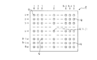
被検体の透過X線像を検出する放射線検出器としてフラットパネル型2次元放射線検出器(以下、適宜「FPD」と記す)を備えた医用のX線撮像装置(放射線撮像装置)は、図8に示すように、被検体の透過X線像が投影されるFPD2の放射線検出面に放射線検出素子Dが縦M行・横N列の2次元マトリックスでM×N個配置されており、撮影対象の被検体へのX線照射に伴ってFPD2から出力されるX線検出信号に基づいて、図9に示すように、縦m行・横n列の2次元マトリックスで配置されたm×n個の画素Qで構成されるX線画像Pが作成され、画像表示モニタの画面などに映し出される。
A medical X-ray imaging apparatus (radiation imaging apparatus) provided with a flat panel type two-dimensional radiation detector (hereinafter referred to as “FPD” as appropriate) as a radiation detector for detecting a transmission X-ray image of a subject is shown in FIG. As shown in FIG. 4, M × N radiation detection elements D are arranged in a two-dimensional matrix of vertical M rows and horizontal N columns on the radiation detection surface of the
一方、FPD2はイメージインテンシファイアに比べて軽量で薄型であるが、製造工程等で生じた欠損を持つ放射線検出素子Dが不可避的に存在する。この欠損のある放射線検出素子Dに対応するX線検出信号は適正な画素値(信号強度)を持たない異常な信号であり、X線画像Pに欠損画素をもたらす。そこで、異常なX線検出信号の画素値を、周辺の正常なX線検出信号の画素値に置き換えたり、あるいは前後の正常なX線検出信号の画素値を用いて算出した補間値に置き換えたりする処理をリアルタイムで行なうことで、異常なX線検出信号を修復している(例えば、特許文献1参照。)。 On the other hand, the FPD 2 is lighter and thinner than the image intensifier, but there is unavoidably a radiation detection element D having defects generated in the manufacturing process or the like. The X-ray detection signal corresponding to the defective radiation detection element D is an abnormal signal that does not have an appropriate pixel value (signal intensity), and causes a defective pixel in the X-ray image P. Therefore, the pixel value of the abnormal X-ray detection signal is replaced with the pixel value of the surrounding normal X-ray detection signal, or the interpolation value calculated using the pixel values of the preceding and succeeding normal X-ray detection signals. The abnormal X-ray detection signal is repaired by performing the processing in real time (see, for example, Patent Document 1).
他方、従来のX線撮像装置では、X線画像Pとして、画素Q(i,j) の配置が放射線検出素子Dの2次元マトリックス配置と同じ2次元マトリックス配置で放射線検出素子D(I,J) が画素Q(i,j) に対し1対1で割り振られている(即ち,M=m,N=n)画素からなる標準X線画像だけでなく、画素Q(i,j) に対する放射線検出器の放射線検出素子D(I,J) の割り振り方が標準X線画像と相違する非標準X線画像も取得できる。 On the other hand, in the conventional X-ray imaging apparatus, as the X-ray image P, the radiation detection element D (I, J) has the same arrangement of the pixels Q (i, j) as the two-dimensional matrix arrangement of the radiation detection element D. ) Is assigned to the pixel Q (i, j) on a one-to-one basis (i.e., M = m, N = n), as well as a radiation for the pixel Q (i, j). A non-standard X-ray image in which the radiation detection elements D (I, J) of the detector are allocated differently from the standard X-ray image can also be acquired.
非標準X線画像としては、例えば縦2個・縦2個の2×2ミニマトリックス配置の4個ずつの放射線検出素子Dが各画素Q(i,j) に割り振られている4素子束ねのX線画像や、縦・横とも2/3ずつの(2/3)M×(2/3)Nの中央のマトリックス範囲の放射線検出素子Dが各画素Q(i,j) に1個ずつ割り振られている2/3限定マトリックスのX線画像が挙げられる。
しかしながら、上記従来のX線撮像装置は、往々にして放射線検出素子Dの欠損に起因して生じる異常なX線検出信号を速やかに修復できないという問題がある。 However, the conventional X-ray imaging apparatus has a problem that an abnormal X-ray detection signal often caused by the loss of the radiation detection element D cannot be quickly repaired.
標準X線画像を取得する場合は、標準X線画像の各画素Qに対応する放射線検出素子Dの欠損の有無が欠損情報として画素Q毎に対応付けして予め記憶されているので、修復対象の異常なX線検出信号が直ぐに分かり、速やかに修復が行なえる。しかし、画素Qに対する放射線検出素子Dの割り振り方が標準X線画像とは違う非標準X線画像を取得する場合は、各画素Qに対応する放射線検出素子Dの欠損の有無が欠損情報として予め記憶されておらず、先ずFPD2から欠損情報取得用の出力信号を収集し放射線検出素子Dの欠損の有無をチェックしなければならないので、異常なX線検出信号を速やかに修復できないのである。
When acquiring a standard X-ray image, the presence or absence of a defect in the radiation detection element D corresponding to each pixel Q of the standard X-ray image is stored in advance as being associated with each pixel Q as defect information. This abnormal X-ray detection signal is immediately known and can be quickly repaired. However, when acquiring a non-standard X-ray image in which the radiation detection element D is assigned to the pixel Q differently from the standard X-ray image, the presence or absence of the defect of the radiation detection element D corresponding to each pixel Q is previously stored as defect information. Since it is not stored and an output signal for acquiring defect information must first be collected from the
この発明は、このような事情に鑑みてなされたものであって、放射線画像の画素に対する放射線検出素子の割り振り方の如何にかかわらず、放射線検出素子の欠損に起因して生じる異常な放射線検出信号を速やかに修復することができる放射線撮像装置を提供することを目的とする。 The present invention has been made in view of such circumstances, and an abnormal radiation detection signal generated due to a defect in the radiation detection element regardless of how the radiation detection elements are allocated to the pixels of the radiation image. An object of the present invention is to provide a radiation imaging apparatus capable of quickly repairing the above.
この発明は、このような目的を達成するために、次のような構成をとる。 In order to achieve such an object, the present invention has the following configuration.
すなわち、請求項1に記載の発明に係る放射線撮像装置は、(A)撮影対象の被検体に放射線を照射する放射線照射手段と、(B)複数個の放射線検出素子が2次元マトリックス配置されている2次元放射線検出器と、(C)画素の配置が放射線検出素子の2次元マトリックス配置と同じ2次元マトリックス配置で放射線検出素子が画素に対し1対1で割り振られている複数個の画素からなる標準放射線画像を取得する標準撮影モードと、画素に対する放射線検出素子の割り振り方が標準撮影モードとは異なる非標準放射線画像を取得する非標準撮影モードのうちの任意の撮影モードを選択して指定する撮影モード指定手段と、(D)標準放射線画像の各画素に対応する各放射線検出素子の欠損の有無が各画素と対応付けされた標準画像用画素欠損情報を記憶する標準画像用欠損情報記憶手段と、(E)標準画像用欠損情報記憶手段に記憶された標準画像用画素欠損情報に基づき、非標準放射線画像の各画素に対して割り振られている放射線検出素子のうちに欠損のある素子が「一つでも有る」か「全く無い」かを各画素毎にチェックすると共に、「一つでも有る」という画素は「欠損有り」と判定し、「全く無い」という画素は「欠損無し」と判定する欠損判定を行なって、標準画像用画素欠損情報を非標準放射線画像の各画素に対応する各放射線検出素子の欠損の有無が各画素と対応付けされた非標準画像用画素欠損情報へ変換する変換処理を行なう画素欠損情報変換手段と、(F)撮影モード指定手段で標準撮影モードが指定された時は標準画像用画素欠損情報にしたがって放射線検出信号を修復し、撮影モード指定手段で非標準撮影モードが指定された時は非標準画像用画素欠損情報にしたがって放射線検出信号を修復する信号修復手段とを備えていることを特徴とするものである。 That is, the radiation imaging apparatus according to the first aspect of the present invention includes (A) a radiation irradiating means for irradiating a subject to be imaged and (B) a plurality of radiation detecting elements arranged in a two-dimensional matrix. And (C) a plurality of pixels in which the arrangement of the pixels is the same as the two-dimensional matrix arrangement of the radiation detection elements and the radiation detection elements are assigned one-to-one to the pixels. Select any imaging mode from the standard imaging mode for acquiring the standard radiographic image and the non-standard imaging mode for acquiring the nonstandard radiographic image in which the radiation detection elements are assigned to the pixels different from the standard imaging mode. And (D) a standard image image in which the presence or absence of a defect of each radiation detection element corresponding to each pixel of the standard radiation image is associated with each pixel. Based on the standard image defect information storage means for storing the defect information and (E) standard image pixel defect information stored in the standard image defect information storage means, it is allocated to each pixel of the non-standard radiation image. While checking for each pixel whether there is a missing element or "not at all" among the radiation detection elements that are present, the pixel that is "even at least" is determined to be "has a defect" A pixel that is “not at all” is determined to be “no defect” and a defect determination is performed. The pixel defect information for the standard image corresponds to each pixel for the presence or absence of each radiation detection element corresponding to each pixel of the non-standard radiation image. Pixel defect information conversion means for performing conversion processing for conversion to attached non-standard image pixel defect information, and (F) when the standard photographing mode is designated by the photographing mode designation means, according to the standard image pixel defect information. And a signal repairing unit for repairing the radiation detection signal and for repairing the radiation detection signal according to the pixel defect information for the nonstandard image when the nonstandard shooting mode is specified by the shooting mode specifying unit. Is.
[作用・効果]請求項1の発明の放射線撮像装置では、撮影モード指定手段で標準撮影モードが指定された場合、放射線照射手段による被検体への放射線照射に伴って2次元放射線検出器から出力される放射線検出信号を、標準放射線画像の各画素に対応する各放射線検出素子の欠損の有無が各画素と対応付けされた標準画像用画素欠損情報に従って、各画素の中で放射線検出素子に欠損が有るとされている画素についての放射線検出信号を信号修復手段で修復し、欠損画素の無い標準放射線画像を取得する。 [Operation / Effect] In the radiation imaging apparatus according to the first aspect of the invention, when the standard imaging mode is designated by the imaging mode designating unit, the radiation is output from the two-dimensional radiation detector as the subject is irradiated with radiation. The detected radiation detection signal is lost to the radiation detection element in each pixel according to the standard image pixel defect information in which the presence or absence of each radiation detection element corresponding to each pixel of the standard radiation image is associated with each pixel. A radiation detection signal for a pixel that is supposed to have a pixel is repaired by a signal repairing means, and a standard radiation image without a defective pixel is acquired.
一方、撮影モード指定手段で非標準撮影モードが指定された場合、被検体への放射線照射に伴って2次元放射線検出器から出力される放射線検出信号を、非標準放射線画像の各画素に対応する各放射線検出素子の欠損の有無が各画素と対応付けされた非標準画像用画素欠損情報に従って、各画素の中で放射線検出素子に欠損が有るとされている画素についての放射線検出信号を信号修復手段で修復し、欠損画素の無い非標準放射線画像を取得する。 On the other hand, when the non-standard imaging mode is specified by the imaging mode specifying means, the radiation detection signal output from the two-dimensional radiation detector when the subject is irradiated with radiation corresponds to each pixel of the non-standard radiation image. In accordance with the non-standard image pixel defect information in which the presence or absence of each radiation detection element is associated with each pixel, the radiation detection signal for the pixel in which the radiation detection element is deemed defective is signal-repaired in each pixel A non-standard radiographic image free from missing pixels is acquired by means.
そして、非標準放射線画像用の放射線検出信号の修復に用いられる非標準画像用画素欠損情報は、画素欠損情報変換手段が、標準画像用画素欠損情報に基づき、非標準放射線画像の各画素に対して割り振られている放射線検出素子のうちに欠損のある素子が「一つでも有る」か「全く無い」かを各画素毎にチェックすると共に、「一つでも有る」という画素は「欠損有り」と判定し、「全く無い」という画素は「欠損無し」と判定する欠損判定を行なって、標準画像用画素欠損情報から変換したものであるので、非標準画像用画素欠損情報の取得の為に2次元放射線検出器から欠損情報取得用の出力信号を改めて収集する必要がない。 The non-standard image pixel defect information used for the restoration of the radiation detection signal for the non-standard radiographic image is obtained by the pixel defect information conversion means for each pixel of the non-standard radiological image based on the standard image pixel defect information. In addition, it is checked for each pixel whether there is a missing element among the radiation detection elements assigned to each pixel, or if there is none at all. In order to obtain non-standard image pixel defect information, a pixel that is “not at all” is converted from the standard image pixel defect information. There is no need to newly collect output signals for acquiring defect information from the two-dimensional radiation detector.
すなわち、請求項1の発明の放射線撮像装置の場合、標準撮影モードが指定された時は、2次元放射線検出器から出力される放射線検出信号の中で放射線検出素子の欠損に起因して生じる異常な放射線検出信号を、信号修復手段が標準画像用欠損情報記憶手段に記憶されている標準画像用画素欠損情報に従って修復し、非標準撮影モードが指定された時は、2次元放射線検出器から出力される放射線検出信号の中で放射線検出素子の欠損に起因して生じる異常な放射線検出信号を、信号修復手段が画素欠損情報変換手段によって標準画像用画素欠損情報から転換された非標準画像用画素欠損情報に従って修復する構成を備えていて、非標準放射線画像用の欠損情報は標準放射線画像用の欠損情報を利用して取得されるので、改めて2次元放射線検出器から非標準画像用画素欠損情報取得用の出力信号を収集する必要がない。 That is, in the radiation imaging apparatus according to the first aspect of the invention, when the standard imaging mode is designated, an abnormality caused by a defect of the radiation detection element in the radiation detection signal output from the two-dimensional radiation detector. When the non-standard radiography mode is designated, the signal restoration means restores the radiation detection signal according to the standard image pixel defect information stored in the standard image defect information storage means, and outputs it from the two-dimensional radiation detector. A non-standard image pixel in which an abnormal radiation detection signal generated due to a defect of a radiation detection element in a generated radiation detection signal is converted from pixel defect information for standard image by a pixel defect information conversion unit Since it has a configuration to repair according to the defect information, the defect information for the non-standard radiographic image is obtained using the defect information for the standard radiographic image. There is no need to collect the output signal of the pixel defect information acquisition nonstandard image from the detector.
その結果、非標準放射線画像を取得する時も、放射線検出素子の欠損に起因して生じる異常な放射線検出信号を速やかに修復できる。 As a result, even when a non-standard radiation image is acquired, an abnormal radiation detection signal generated due to the loss of the radiation detection element can be quickly repaired.
また、請求項2に記載の発明は、請求項1に記載の放射線撮像装置において、(G)画素欠損情報変換手段で変換された非標準画像用画素欠損情報を記憶する非標準画像用欠損情報記憶手段を備えていて、信号修復手段が、非標準画像用欠損情報記憶手段に記憶されている非標準画像用画素欠損情報にしたがって放射線検出信号を修復するものである。
The invention described in
[作用・効果]請求項2の発明の放射線撮像装置の場合、非標準放射線画像用の放射線検出信号の修復に用いられる非標準画像用画素欠損情報が非標準画像用欠損情報記憶手段に記憶されていて、標準画像用画素欠損情報を非標準画像用画素欠損情報に変換しなくても非標準画像用画素欠損情報を用いることができるので、異常な放射線検出信号の修復がより速やかに行なえる。
[Operation / Effect] In the radiation imaging apparatus of the invention of
また、請求項3に記載の発明は、請求項1に記載の放射線撮像装置において、画素欠損情報変換手段は、撮影モード指定手段による非標準撮影モードの指定があってから、標準画像用画素欠損情報を撮影モード指定手段で指定された非標準撮影モードの非標準放射線画像に相応する非標準画像用画素欠損情報へ変換して信号修復手段へ送り込むものである。 According to a third aspect of the present invention, in the radiation imaging apparatus according to the first aspect, the pixel defect information converting unit is configured to perform the standard image pixel defect after the non-standard photographing mode is designated by the photographing mode designating unit. The information is converted into non-standard image pixel defect information corresponding to the non-standard radiographic image in the non-standard imaging mode designated by the imaging mode designating means and sent to the signal restoration means.
[作用・効果]請求項3の発明の放射線撮像装置の場合、画素欠損情報変換手段は、撮影モード指定手段による非標準撮影モードの指定があってから、標準画像用画素欠損情報から非標準画像用画素欠損情報影への変換処理が行なわれるので、標準画像用画素欠損情報から非標準画像用画素欠損情報への転換はリアルタイム変換となる結果、非標準画像用画素欠損情報に必ず最新の標準画像用画素欠損情報が反映されるのに加えて、画素欠損情報変換手段は、撮影モード指定手段による非標準撮影モードの指定があってから、非標準画像用画素欠損情報が画素欠損情報変換手段から信号修復手段へ送り込まれるので、非標準画像用画素欠損情報を記憶しなくて済む。
[Operation / Effect] In the case of the radiation imaging apparatus according to the invention of
また、請求項4に記載の発明は、請求項2に記載の放射線撮像装置において、標準画像用欠損情報記憶手段に標準画像用画素欠損情報が記憶されるのに引き続いて、画素欠損情報変換手段による非標準画像用画素欠損情報への変換処理と非標準画像用欠損情報記憶手段への非標準画像用画素欠損情報の記憶が全ての非標準放射線画像について行なわれるものである。 According to a fourth aspect of the present invention, in the radiation imaging apparatus according to the second aspect of the present invention, the pixel defect information converting means is stored after the standard image pixel defect information is stored in the standard image defect information storing means. The nonstandard image pixel defect information is converted into the nonstandard image pixel defect information and the nonstandard image pixel defect information is stored in the nonstandard image defect information storage means for all the nonstandard radiographic images.
[作用・効果]請求項4の発明の放射線撮像装置の場合、標準画像用欠損情報記憶手段に標準画像用画素欠損情報が記憶されるのに引き続いて、全ての非標準放射線画像について、画素欠損情報変換手段による非標準画像用画素欠損情報への変換処理と非標準画像用欠損情報記憶手段への非標準画像用画素欠損情報の記憶とが行なわれるので、標準画像用画素欠損情報の記憶に続いて、全ての非標準放射線画像についての非標準画像用画素欠損情報の記憶を速やかに完了させることができる。 [Operation / Effect] In the case of the radiation imaging apparatus according to the fourth aspect of the present invention, pixel defect information is obtained for all non-standard radiation images following the standard image pixel defect information being stored in the standard image defect information storage means. Conversion processing to non-standard image pixel defect information by the information conversion means and storage of non-standard image pixel defect information in the non-standard image defect information storage means are performed, so that standard image pixel defect information can be stored. Subsequently, storage of non-standard image pixel defect information for all non-standard radiographic images can be quickly completed.
また、請求項5に記載の発明は、請求項1から4のいずれかに記載の放射線撮像装置において、撮影モード指定手段は、放射線検出素子が複数個ずつ束ねられて各画素に割り振られている非標準放射線画像を取得する非標準撮影モードが指定できるものである。 According to a fifth aspect of the present invention, in the radiation imaging apparatus according to any one of the first to fourth aspects, the imaging mode designating unit is configured to allocate a plurality of radiation detection elements to each pixel in a bundle. A nonstandard imaging mode for acquiring a nonstandard radiographic image can be specified.
[作用・効果]請求項5の発明の放射線撮像装置の場合、撮影モード指定手段で画素に対し放射線検出素子が複数個ずつ束ねられて割り振られている非標準放射線画像を取得する非標準撮影モードが指定されると、各画素が複数個の放射線検出素子の放射線検出信号で造られている非標準放射線画像が取得される。
[Operation / Effect] In the radiation imaging apparatus according to the invention of
また、請求項6に記載の発明は、請求項1から5のいずれかに記載の放射線撮像装置において、撮影モード指定手段は、一定の限られたマトリックス範囲の放射線検出素子が各画素に割り振られている非標準放射線画像を取得する非標準撮影モードが指定できるものである。 According to a sixth aspect of the present invention, in the radiation imaging apparatus according to any one of the first to fifth aspects, the imaging mode designating unit allocates radiation detection elements in a certain limited matrix range to each pixel. A non-standard imaging mode for acquiring a non-standard radiographic image can be specified.
[作用・効果]請求項6の発明の放射線撮像装置の場合、撮影モード指定手段で画素に対し全放射線検出素子の中の一定の限られたマトリックス範囲の放射線検出素子だけが割り振られている非標準放射線画像を取得する非標準撮影モードが指定されると、一定の限られたマトリックス範囲の放射線検出素子の放射線検出信号だけで造られている非標準放射線画像が取得される。
[Operation / Effect] In the radiation imaging apparatus according to the invention of
請求項1の発明の放射線撮像装置の場合、標準撮影モードが指定された時は、2次元放射線検出器から出力される放射線検出信号の中で放射線検出素子の欠損に起因して生じる異常な放射線検出信号を、信号修復手段が標準画像用欠損情報記憶手段に記憶されている標準画像用画素欠損情報に従って修復し、非標準撮影モードが指定された時は、2次元放射線検出器から出力される放射線検出信号の中で放射線検出素子の欠損に起因して生じる異常な放射線検出信号を、信号修復手段が画素欠損情報変換手段によって標準画像用画素欠損情報から転換された非標準画像用画素欠損情報に従って修復する構成を備えていて、非標準放射線画像用の欠損情報は標準放射線画像用の欠損情報を利用して取得されるので、改めて2次元放射線検出器から非標準画像用画素欠損情報取得用の出力信号を収集する必要がない。 In the case of the radiation imaging apparatus according to the first aspect of the invention, when the standard imaging mode is designated, abnormal radiation generated due to a defect of the radiation detection element in the radiation detection signal output from the two-dimensional radiation detector. When the non-standard imaging mode is designated when the signal restoration unit repairs the detection signal according to the standard image pixel defect information stored in the standard image defect information storage unit, the detection signal is output from the two-dimensional radiation detector. Non-standard image pixel defect information obtained by converting an abnormal radiation detection signal generated due to a defect of the radiation detection element in the radiation detection signal from pixel defect information for standard image by a pixel defect information conversion unit. The defect information for the non-standard radiographic image is acquired using the defect information for the standard radiographic image. There is no need to collect the output signal of the pixel defect information acquisition non-standard image.
よって、請求項1の発明の放射線撮像装置によれば、放射線画像の画素に対する放射線検出素子の割り振り方の如何にかかわらず、放射線検出素子の欠損に起因して生じる異常な放射線検出信号を速やかに修復することができる。 Therefore, according to the radiation imaging apparatus of the first aspect of the present invention, an abnormal radiation detection signal generated due to the loss of the radiation detection element can be promptly generated regardless of how the radiation detection elements are allocated to the pixels of the radiation image. Can be repaired.
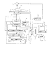
この発明の実施例1を図面を参照して説明する。図1は実施例1に係るX線撮像装置(放射線撮像装置)全体の構成を示すブロック図である。 A first embodiment of the present invention will be described with reference to the drawings. FIG. 1 is a block diagram illustrating the overall configuration of the X-ray imaging apparatus (radiation imaging apparatus) according to the first embodiment.
図1に示す実施例1のX線撮像装置は、撮影対象の被検体Mに放射線であるX線を照射するX線管1と、図8に示すように、放射線検出素子Dが縦M行・横N列の2次元マトリックスで放射線検出面にM×N個配置されているフラットパネル型2次元X線検出器(以下、適宜「FPD」2と略記)2とを備えている。X線管1とFPD2とは撮影対象の被検体Mを挟んで常に対向しており、X線管1が照射制御部1Aの制御を受けながら被検体MにX線を照射すると、X線照射に伴って生じる被検体Mの透過X線像がFPD2の放射線検出面に投影される配置関係となっている。
The X-ray imaging apparatus according to the first embodiment shown in FIG. 1 includes an
そして、X線撮影中は、X線管1が被検体MにX線を照射すると共に、FPD2が被検体Mの透過X線像を検出し、さらにFPD2の後段において、FPD2から出力されるX線検出信号にしたがって、図9に示すように、縦m行・横n列の2次元マトリックスで配置されたm×n個の画素Qで構成されるX線画像Pが取得される。
During X-ray imaging, the
FPD2は、例えば、縦30〜50cm×横30〜50cm程の広さの放射線検出面に放射線検出素子Dが縦2048(=M)行・横2048(=N)列の2次元マトリックスで配置されている直接変換タイプのX線検出器である。
In the
FPD2の場合、図2に示すように、例えばa−Se系半導体膜などの入射X線を直接電荷に変換する放射線有感体3と、放射線有感体3の表面へ面状に積層形成されているバイアス電圧印加用の共通電極4と、図3に示すように、多数の個別電極5が放射線検出素子Dの2次元状マトリックス配置でもって表面に形成されていると共に各個別電極5で収集される電荷の蓄積・読み出し用電気回路6が配設されているアクティブマトリックス基板7とを備えていて、放射線有感体3がアクティブマトリックス基板7の個別電極5を形成した側に積層されている。
In the case of the
蓄積・読み出し用電気回路6はコンデンサ6Aやスイッチング素子としてのTFT(薄膜電界効果トランジスタ)6Bおよび電気配線6a,6bなどからなり、各個別電極5ごとに1個のコンデンサ6Aと1個のTFT6Bが割り当てられている。
The
また、図3に示すように、蓄積・読み出し用電気回路6の周りにはゲートドライバ8と電荷電圧変換型増幅器9およびマルチプレクサ10に加えてA/D変換器11などが別デバイスのかたちで配備接続されている。
As shown in FIG. 3, an A / D converter 11 is provided in the form of a separate device in addition to the
FPD2によりX線を検出する場合、バイアス電圧が共通電極4から放射線有感体3に印加され、検出対象のX線の入射に伴って放射線有感体3で電荷が生成されると共に放射線有感体3で生じた電荷が(詳しくは各個別電極5へ移動することで個別電極5に電荷が誘起生成するかたちで)各個別電極5ごとに収集される一方、各個別電極5で収集される電荷は、アクティブマトリックス基板7の蓄積・読み出し用電気回路6などにより個別電極5毎に取り出される。
When X-rays are detected by the
具体的には、ゲートドライバ8から電気配線6a経由で読み出し信号が各TFT6Bのゲートに順番に与えられると同時に、読み出し信号が与えられている各TFT6Bのソースに繋がっている電気配線6bが電荷電圧変換型増幅器9を介してマルチプレクサ10に順に切り換え接続されるのに伴って、コンデンサ6Aに蓄積された電荷が、TFT6Bから電気配線6bを経て、さらに電荷電圧変換型増幅器9で増幅された上で、マルチプレクサ10により各個別電極5毎にA/D変換器11へ送り出されてディジタル化されてから放射線検出素子D毎のX線検出信号として出力される。
Specifically, the readout signal is sequentially applied from the
つまり、FPD2では、一つの個別電極5と個別電極5の広さ相当の放射線有感体3および共通電極4に加えて1個のコンデンサ6Aおよび1個のTFT6Bとで一つの放射線検出素子Dが構成されている。そして、FPD2におけるX線検出信号の出力(読み出しは)は、水平ラインに沿って左側の放射線検出素子Dから右側の素子へ移りながら順番に進行し、一本の水平ラインを終われば、一段下の水平ラインに移って同様にX線検出信号の読み出しを行なうプロセスが水平ライン毎に繰り返えされる。
That is, in the
さらに、FPD2の後段には、FPD2から出力されたX線検出信号に対して(例えばオフセット補正や感度補正を始めとして)X線画像取得に必要な処理を行なう信号処理部12と、X線画像記憶用の放射線画像信号メモリ13と、X線画像を表示する画像表示装置14が配設されていて、X線管1による被検体MへのX線照射に伴ってFPD2から出力されるX線検出信号にしたがって信号処理部12でX線画像が取得されて放射線画像信号メモリ13に記憶されると共に、画像表示装置14の画面には取得・記憶されたX線画像が表示される。
Further, following the
一方、FPD2は、イメージインテンシファイアに比べて軽量で薄型であるが、放射線検出素子Dの中に製造工程等で生じた欠損を持つものが不可避的に存在する。この欠損のある放射線検出素子Dに対応するX線検出信号は画素値(信号強度)が適正でない異常な信号であり、X線画像Pに欠損画素をもたらす。そこで、実施例1の装置の場合、信号処理部12に異常なX線検出信号の画素値を、周辺の正常なX線検出信号の画素値に置き換えたり、あるいは前後の正常なX線検出信号の画素値を用いて算出した補間値に置き換えたりする補正処理をリアルタイムで行なう信号修復部15が設けられている。
On the other hand, the
他方、実施例1のX線撮像装置の場合、画素Q(i,j) の配置が放射線検出素子Dの2次元マトリックス配置と同じ2次元マトリックス配置で放射線検出素子D(I,J) が画素Q(i,j) に対し1対1で割り振られているM×N個(即ち2048×2048個)の画素からなる標準X線画像を取得する標準撮影モード、および、画素Q(i,j) に対する放射線検出素子Dの割り振り方が標準撮影モードとは異なる非標準X線画像(非標準放射線画像)を取得する非標準撮影モードのうちの任意の撮影モードを選択して指定する撮影モード指定部16が設けられている。
On the other hand, in the case of the X-ray imaging apparatus according to the first embodiment, the radiation detection element D (I, J) is arranged in the same two-dimensional matrix arrangement as that of the radiation detection element D in the arrangement of the pixels Q (i, j). A standard imaging mode for acquiring a standard X-ray image composed of M × N (that is, 2048 × 2048) pixels allocated one-to-one with respect to Q (i, j), and pixel Q (i, j ) Specifying an imaging mode for selecting and specifying an arbitrary imaging mode among non-standard imaging modes for acquiring non-standard X-ray images (non-standard radiographic images) in which the radiation detection element D is allocated to the standard imaging mode. A
撮影モード指定部16で指定できる非標準撮影モードとしては、放射線検出素子Dが複数個ずつ束ねられたかたちで各画素Qに割り振られている束ねX線画像(非標準X線画像)を取得する束ね撮影モードと、一定の限られたマトリックス範囲の放射線検出素子Dが各画素Qに割り振られている限定X線画像(非標準X線画像)を取得する限定撮影モードがある。
As a non-standard imaging mode that can be specified by the imaging
束ね撮影モードの場合は、各画素Qが複数個の放射線検出素子DのX線検出信号で造られている非標準X線画像が取得され、限定撮影モードの場合は、一定の限られたマトリックス範囲の放射線検出素子DのX線検出信号だけで造られている非標準X線画像が取得される。 In the bundled imaging mode, a non-standard X-ray image in which each pixel Q is formed by X-ray detection signals from a plurality of radiation detection elements D is acquired. In the limited imaging mode, a certain limited matrix is obtained. A non-standard X-ray image created only from the X-ray detection signal of the radiation detection element D in the range is acquired.
標準撮影モードは、例えば高精細なX線画像の撮影に適し、束ね撮影モードは、例えば透視撮影等の低線量のX線画像の撮影に適しており、限定撮影モードは、例えばサイズ変換画像や限定視野画像の撮影に適している。 The standard imaging mode is suitable for photographing a high-definition X-ray image, for example, and the bundle photographing mode is suitable for photographing a low-dose X-ray image such as fluoroscopic imaging, and the limited imaging mode is, for example, a size-converted image or Suitable for taking limited field images.
なお、各撮影モードの選択操作は、マウスやキーボード等の入力機器で構成される操作部17を用いて行なわれる。
Note that the selection operation of each shooting mode is performed using the
具体的な束ね撮影モードとしては、図4(a)に示すように、縦・横共に2個の2×2ミニマトリックスの4個ずつで放射線検出素子Dが順に各画素Qに割り振られている2×2束ねX線画像を取得する2×2束ね撮影モードや、図4(b)に示すように、縦・横共に4個の4×4ミニマトリックスの16個ずつで放射線検出素子Dが各画素Qに割り振られている4×4束ねX線画像を取得する4×4束ね撮影モードがある。 As a specific bundle imaging mode, as shown in FIG. 4A, the radiation detection element D is assigned to each pixel Q in order of four 2 × 2 mini-matrices both vertically and horizontally. As shown in FIG. 4 (b), the radiation detection element D is provided with 16 pieces of 4 × 4 mini-matrices in both the vertical and horizontal directions as shown in FIG. 4B. There is a 4 × 4 bundle imaging mode for acquiring a 4 × 4 bundled X-ray image assigned to each pixel Q.
2×2束ねX線画像では1個の画素Qが4個の放射線検出素子DのX線検出信号で造られていることになり、4×4束ねX線画像では1個の画素Qが16個の放射線検出素子DのX線検出信号で造られていることになる。 In the 2 × 2 bundled X-ray image, one pixel Q is formed by the X-ray detection signals of the four radiation detection elements D, and in the 4 × 4 bundled X-ray image, one pixel Q is 16 in number. The X-ray detection signals of the individual radiation detection elements D are produced.
具体的な限定撮影モードとしては、図5に一点鎖線で示すように、縦・横とも2/3ずつの1536×1536のマトリックス範囲の放射線検出素子Dが各画素Qに1個ずつ割り振られている2/3限定X線画像を取得する2/3限定撮影モードや、図5に二点鎖線で示すように、縦・横とも1/2ずつの1024×1024のマトリックス範囲の放射線検出素子Dが各画素Qに1個ずつ割り振られている1/2限定X線画像を取得する1/2限定撮影モードが挙げられる。 As a specific limited imaging mode, as shown by a one-dot chain line in FIG. 5, a radiation detection element D having a matrix range of 1536 × 1536 of 2/3 each in vertical and horizontal directions is assigned to each pixel Q one by one. 2/3 limited radiographing mode for acquiring a 2/3 limited X-ray image, and a radiation detection element D in a matrix range of 1024 × 1024 in both vertical and horizontal directions as shown by a two-dot chain line in FIG. Is a 1/2 limited imaging mode that acquires a 1/2 limited X-ray image in which one pixel Q is allocated to each pixel Q.
2/3限定X線画像は、真ん中の1536×1536のマトリックス範囲に投影された透過X線像に対応する画像となり、1/2限定X線画像は、真ん中の1024×1024のマトリックス範囲に投影された透過X線像に対応する画像となる。 The 2/3 limited X-ray image corresponds to the transmitted X-ray image projected on the middle 1536 × 1536 matrix range, and the 1/2 limited X-ray image is projected on the middle 1024 × 1024 matrix range. An image corresponding to the transmitted X-ray image is obtained.
さらに、実施例1のX線撮像装置は、標準X線画像の各画素Qに対応する各放射線検出素子Dの欠損の有無が各画素Qと対応付けされた標準画像用画素欠損情報(以下、適宜「欠損情報」と略記)を記憶する標準画像用欠損情報メモリ18Aを備えているのに加えて、標準画像用欠損情報メモリ18Aに記憶されている欠損情報に基づき、それぞれの非標準X線画像の各画素Qに対して割り振られている放射線検出素子Dのうちに欠損のある素子が「一つでも有る」か「全く無い」かを各画素Q毎にチェックすると共に、「一つでも有る」という画素Qは「欠損有り」と判定し、「全く無い」という画素Qは「欠損無し」と判定する欠損判定を行なって、標準画像用画素欠損情報を非標準X線画像の各画素Qに対応する各放射線検出素子Dの欠損の有無が各画素Qと対応付けされた非標準画像用画素欠損情報(以下、適宜「欠損情報」と略記)へ変換する変換処理を行なう画素欠損情報変換部19と、画素欠損情報変換部19で変換された非標準画像用画素欠損情報を非標準X線画像毎に記憶する欠損情報メモリ18B〜18Eとを備えている。
Furthermore, the X-ray imaging apparatus according to the first embodiment includes standard image pixel defect information (hereinafter, referred to as “defects”) in which each radiation detection element D corresponding to each pixel Q of the standard X-ray image is associated with each pixel Q. In addition to the standard image missing
標準X線画像についての欠損情報は、全放射線検出素子Dの個々についての情報であるので、標準画像用欠損情報メモリ18Aに記憶されている欠損情報は、全放射線検出素子Dの各素子毎に逐一欠損が有るか無いかを示す素子欠損データとなる。
Since the defect information about the standard X-ray image is information about each of all the radiation detection elements D, the defect information stored in the standard image
なお、標準画像用欠損情報メモリ18Aに記憶される標準X線画像についての欠損情報の記憶は次のようにして行なわれる。先にFPD2から欠損情報取得用の出力信号(各放射線検出素子の例えばオフセット信号)を全放射線検出素子Dから収集し、標準画像用欠損情報取得部20が、収集した欠損情報取得用の出力信号の信号強度を一つずつ異常値か否かをチェックして放射線検出素子D毎に欠損の有無を判定する。標準画像用欠損情報メモリ18Aは、標準画像用欠損情報取得部20の判定結果を欠損情報として記憶する。
It should be noted that the defect information for the standard X-ray image stored in the standard image
画素欠損情報変換部19は、2×2束ねX線画像の場合、標準画像用欠損情報メモリ18Aに記憶されている素子欠損データを参照し、各画素Qごとに4個の放射線検出素子Dのそれぞれについて欠損の有無をチェックし一つでも欠損を持つ素子があれば、欠損有りと判定して、4個の素子全てが欠損を持たないならば欠損無しと判定し、標準画像用画素欠損情報を2×2束ねX線画像の各画素Qに対応する各放射線検出素子Dの欠損の有無が各画素Qと対応付けされた2×2束ねX線画像用画素欠損情報へ変換する。2×2画像用欠損情報メモリ18Bは、画素欠損情報変換部19で変換された2×2束ねX線画像用画素欠損情報を記憶する。
In the case of a 2 × 2 bundled X-ray image, the pixel defect
4×4束ねX線画像の場合も、画素欠損情報変換部19は、標準画像用欠損情報メモリ18Aに記憶されている素子欠損データを参照し、各画素Qごとに16個の放射線検出素子Dの中の一つでも欠損があれば、欠損有りと判定して、16個の素子全てが欠損無しならば欠損無しと判定し、標準画像用画素欠損情報を4×4束ねX線画像の各画素Qに対応する各放射線検出素子Dの欠損の有無が各画素Qと対応付けされた4×4束ねX線画像用画素欠損情報へ変換する。4×4画像用欠損情報メモリ18Cは、画素欠損情報変換部19で変換された4×4束ねX線画像用画素欠損情報を記憶する。
Also in the case of a 4 × 4 bundled X-ray image, the pixel defect
2/3限定X線画像の場合、画素欠損情報変換部19は、標準画像用欠損情報メモリ18Aに記憶されている素子欠損データを参照し、各画素Qごとに対応する放射線検出素子Dに欠損があれば、欠損有りと判定して、放射線検出素子Dに欠損が無ければ欠損無しと判定し、標準画像用画素欠損情報を2/3限定X線画像の各画素Qに対応する各放射線検出素子Dの欠損の有無が各画素Qと対応付けされた2/3限定X線画像用画素欠損情報へ変換する。2/3画像用欠損情報メモリ18Dは、画素欠損情報変換部19で変換された2/3限定X線画像用画素欠損情報を記憶する。
In the case of a 2/3 limited X-ray image, the pixel defect
1/2限定X線画像の場合も、画素欠損情報変換部19は、標準画像用欠損情報メモリ18Aに記憶されている素子欠損データを参照し、各画素Qごとに対応する放射線検出素子Dに欠損があれば、欠損有りと判定して、放射線検出素子Dに欠損が無ければ欠損無しと判定し、標準画像用画素欠損情報を1/2限定X線画像の各画素Qに対応する各放射線検出素子Dの欠損の有無が各画素Qと対応付けされた1/2限定X線画像用画素欠損情報へ変換する。1/2画像用欠損情報メモリ18Eは、画素欠損情報変換部19で変換された1/2限定X線画像用画素欠損情報を記憶する。
Also in the case of a ½ limited X-ray image, the pixel defect
なお、実施例1の装置では、加えて、標準画像用欠損情報メモリ18Aに標準X線画像用の欠損情報が記憶されるのに引き続き、画素欠損情報変換部19による欠損判定と他の非標準X線画像用の各欠損情報メモリ18B〜18Eへの欠損情報の記憶が全ての非標準X線画像について行なわれる構成とされている。
In addition, in the apparatus of the first embodiment, the defect information for the standard X-ray image is stored in the standard image
そして、撮影モード指定部16で標準撮影モードが指定された場合、信号修復部15は、標準画像用欠損情報メモリ18Aに記憶されている欠損情報にしたがって、欠損が有りと記憶されている画素Qについては、異常なX線検出信号を修復する。その結果、欠損画素のないX線画像が取得される。
When the standard shooting mode is specified by the shooting
また、撮影モード指定部16で2×2束ね撮影モードが指定された場合、信号修復部15は、2×2画像用欠損情報メモリ18Bに記憶されている2×2束ねX線画像用画素欠損情報にしたがって、欠損が有りと記憶されている画素Qについては、異常なX線検出信号を修復する。その結果、欠損画素のないX線画像が取得される。
When the 2 × 2 bundling imaging mode is designated by the imaging
さらに、4×4束ね撮影モードや2/3限定撮影モードあるいは1/2限定撮影モードが指定された場合も、やはり4×4画像用欠損情報メモリ18Cや2/3画像用欠損情報メモリ18Dあるいは1/2画像用欠損情報メモリ18Eに記憶されている各欠損情報にしたがって、信号修復部15が異常なX線検出信号を修復するので、欠損画素のないX線画像が取得される。
Further, when the 4 × 4 bundle shooting mode, the 2/3 limited shooting mode, or the 1/2 limited shooting mode is designated, the 4 × 4 image missing information memory 18C or the 2/3 image missing
なお、主制御部21は、主としてコンピュータ(CPU)およびその制御プログラムから構成されており、操作部17で行なわれる入力操作や撮影の進み具合に応じて各部に制御用の指令信号や必要なデータを送出する司令機能を発揮し、撮影の全体的な進行を司る役割を果たす。
The
続いて、上述した構成を有するX線撮像装置において欠損情報が記憶される時のプロセスを図面を参照しながら説明する。図6は実施例1の装置での欠損情報の記憶プロセスを示すフローチャートである。 Next, a process when defect information is stored in the X-ray imaging apparatus having the above-described configuration will be described with reference to the drawings. FIG. 6 is a flowchart showing a storage process of missing information in the apparatus of the first embodiment.
〔ステップS1〕FPD2から標準X線画像のX線検出信号の修復に用いる標準X線画像用画素欠損情報を取得する為の出力信号(例えば全放射線検出素子についての個々のオフセット信号)が収集される。
[Step S1] Output signals (for example, individual offset signals for all radiation detection elements) for acquiring standard X-ray image pixel defect information used for restoration of the X-ray detection signal of the standard X-ray image are collected from the
〔ステップS2〕標準画像用欠損情報取得部20が、収集された欠損情報取得用の出力信号の信号強度を一つずつチェックし各放射線検出素子毎に欠損の有無を判定する。
[Step S2] The standard image defect
〔ステップS3〕標準画像用欠損情報メモリ18Aが標準画像用欠損情報取得部20の判定結果を標準X線画像用画素欠損情報として記憶する。
[Step S3] The standard image
〔ステップS4〕画素欠損情報変換部19が、標準画像用欠損情報メモリ18Aに記憶されている素子欠損データを参照して、最初の非標準撮影モード(例えば2×2束ね撮影モード)の非標準X線画像(例えば2×2束ねX線画像)における各画素Qごとに欠損の有無を判定し、標準X線画像用画素欠損情報を非標準X線画像(例えば2×2束ねX線画像)用画素欠損情報へ変換する。
[Step S4] The pixel defect
〔ステップS5〕非標準画像用欠損情報メモリ(例えば2×2画像用欠損情報メモリ18B)が、画素欠損情報変換部19により変換された非標準X線画像(例えば2×2束ねX線画像)用画素欠損情報を記憶する。
[Step S5] Non-standard X-ray image (for example, 2 × 2 bundled X-ray image) obtained by converting the non-standard image defect information memory (for example, 2 × 2 image
〔ステップS6〕欠損情報が未記憶の非標準撮影モードが未だ残っていれば、ステップS4に戻って、欠損情報が未記憶の非標準撮影モードについての欠損情報の変換・記憶処理を繰り返す。 [Step S6] If there is still a non-standard imaging mode in which missing information is not stored, the process returns to step S4 to repeat the conversion / storage processing of the missing information for the non-standard imaging mode in which missing information is not stored.
欠損情報未記憶の非標準撮影モードが残っていなければ、全ての非標準撮影モードの欠損情報の記憶が済み、欠損情報の記憶処理は全て終了したことになる。したがって、如何なる撮影モードが指定されても、直ちに信号修復部15によるX線検出信号の修復を行なえる態勢が整ったことになる。
If there is no non-standard imaging mode in which missing information is not stored, all of the non-standard imaging modes are stored with the missing information, and all of the missing information storage processing is completed. Therefore, no matter what imaging mode is designated, the system is ready to immediately restore the X-ray detection signal by the
以上に述べたように、実施例1のX線撮像装置の場合、撮影モード指定部16で標準撮影モードが指定された時は、FPD2から出力されるX線検出信号の中で放射線検出素子Dの欠損に起因して生じる異常なX線検出信号を、信号修復部15が標準画像用欠損情報メモリ18Aに記憶されている欠損情報に従って修復し、撮影モード指定部16で非標準撮影モードが指定された時は、FPD2から出力されるX線検出信号の中で放射線検出素子Dの欠損に起因して生じる異常なX線検出信号を、信号修復部15が非標準画像用の各欠損情報メモリ18B〜18Eに記憶されている欠損情報に従って修復する構成を備えていて、非標準X線画像用画素欠損情報は、標準X線画像用の欠損情報を利用して取得されるので、改めてFPD2から非標準X線画像用画素欠損情報取得用の出力信号を収集する必要がない。その結果、非標準X線画像を取得する時も、放射線検出素子の欠損に起因して生じる異常なX線検出信号を速やかに修復できる。
As described above, in the case of the X-ray imaging apparatus according to the first embodiment, when the standard imaging mode is specified by the imaging
よって、実施例1の装置によれば、X線画像の画素Qに対する放射線検出素子Dの割り振り方の如何にかかわらず、放射線検出素子Dの欠損に起因して生じる異常なX線検出信号を速やかに修復することができる。 Therefore, according to the apparatus of the first embodiment, an abnormal X-ray detection signal generated due to the loss of the radiation detection element D is promptly generated regardless of how the radiation detection element D is allocated to the pixel Q of the X-ray image. Can be repaired.
また、実施例1の装置の場合、非標準X線画像用のX線検出信号の修復に用いられる非標準画像用画素欠損情報が非標準画像用の各欠損情報メモリ18B〜18Eに記憶されていて、標準画像用画素欠損情報を非標準画像用画素欠損情報に変換しなくても非標準画像用画素欠損情報を用いることができるので、異常な放射線検出信号の修復がより速やかに行なえる。
Further, in the case of the apparatus according to the first embodiment, non-standard image pixel defect information used for repairing an X-ray detection signal for a non-standard X-ray image is stored in each non-standard image
さらに、実施例1の装置の場合、標準画像用欠損情報メモリ18Aに標準X線画像についての欠損情報が記憶されるのに引き続いて、全ての非標準X線画像について画素欠損情報変換部19による欠損判定と画素欠損情報変換部19による欠損情報の記憶が行なわれるので、標準画像用画素欠損情報の記憶に続いて、全ての非標準X線画像についての非標準画像用画素欠損情報の記憶を速やかに完了させることができる。
Further, in the case of the apparatus according to the first embodiment, the defect information on the standard X-ray image is stored in the defect information memory for
この発明の実施例2を図面を参照して説明する。図7は実施例2に係るX線撮像装置(放射線撮像装置)全体の構成を示すブロック図である。実施例2のX線撮像装置の場合、画素欠損情報変換部19Aは、撮影モード指定部16による非標準撮影モードの指定があってから、標準画像用画素欠損情報を撮影モード指定部16で指定された非標準撮影モードの非標準X線画像に相応する非標準画像用画素欠損情報へ変換し信号修復部15へ送り込む構成であるのに加え、欠損情報メモリ18B〜18Eを備えていない他は、実施例1のX線撮像装置と実質的に同一の装置であるので、相違する点を中心に説明し、共通する点の説明は原則として省略する。
A second embodiment of the present invention will be described with reference to the drawings. FIG. 7 is a block diagram illustrating the overall configuration of the X-ray imaging apparatus (radiation imaging apparatus) according to the second embodiment. In the case of the X-ray imaging apparatus according to the second embodiment, the pixel defect
実施例2のX線撮像装置の場合、撮影モード指定部16で標準撮影モードが指定された場合は、実施例1の装置と同様、標準画像用欠損情報メモリ18Aに記憶されている標準画像用画素欠損情報にしたがって信号修復部15が異常なX線検出信号を修復するので、欠損画素のない標準X線画像が取得される。
In the case of the X-ray imaging apparatus according to the second embodiment, when the standard imaging mode is specified by the imaging
しかし、撮影モード指定部16で非標準撮影モードが指定された場合、撮影モード指定部16による非標準撮影モード(例えば2×2束ね撮影モード)の指定があってから、画素欠損情報変換部19Aが、標準画像用画素欠損情報に基づき、撮影モード指定部16で指定された非標準撮影モードの非標準X線画像(例えば2×2束ねX線画像)における各画素Qごとに欠損の有無を判定し、標準X線画像用画素欠損情報を非標準X線画像用(例えば2×2束ねX線画像用)画素欠損情報へ変換する。
However, when the non-standard shooting mode is specified by the shooting
画素欠損情報変換部19Aで変換された非標準X線画像用画素欠損情報は信号修復部15へ送り込まれる。信号修復部15は送り込まれた非標準X線画像用画素欠損情報にしたがって非標準X線画像用(例えば2×2束ねX線画像用)の異常なX線検出信号を修復するので、欠損画素のない非標準X線画像(例えば2×2束ねX線画像)が取得される。
The non-standard X-ray image pixel defect information converted by the pixel defect
このように、実施例2の装置の場合、画素欠損情報変換部19Aは、撮影モード指定部16による非標準撮影モードの指定があってから、標準画像用画素欠損情報から非標準画像用画素欠損情報影への変換処理が行なわれるので、標準画像用画素欠損情報から非標準画像用画素欠損情報への転換はリアルタイム変換となる結果、非標準画像用画素欠損情報に必ず最新の標準画像用画素欠損情報が反映される。加えて、非標準画像用画素欠損情報が画素欠損情報変換部19Aから信号修復部15へ送り込まれるので、非標準画像用画素欠損情報の記憶が必要でなくなる結果、実施例1の装置では必要であった欠損情報メモリ18B〜18Eを省くことができる。
As described above, in the case of the apparatus according to the second embodiment, the pixel defect
この発明は、上記の実施例に限られるものではなく、以下のように変形実施することも可能である。 The present invention is not limited to the above embodiment, and can be modified as follows.
(1)実施例装置の場合、標準X線画像についての欠損情報の記憶に引き続いて、全ての非標準X線画像についての欠損情報の記憶が実行される構成であったが、非標準X線画像についての欠損情報の記憶は、非標準撮影モードの指定があってから指定された非標準撮影モードに係る非標準X線画像についての欠損情報だけが記憶される構成である他は、実施例と同じ構成の装置が、変形例として挙げられる。 (1) In the case of the embodiment apparatus, the storage of the defect information for all the non-standard X-ray images is executed subsequent to the storage of the defect information for the standard X-ray image. The storage of the defect information about the image is a configuration in which only the defect information about the non-standard X-ray image related to the specified non-standard imaging mode is stored after the non-standard imaging mode is specified. An apparatus having the same configuration as that described above is given as a modification.
(2)撮影モード指定部16は、非標準撮影モードとして、放射線検出素子Dが特定個数おきに抽出されたかたちで各画素Qに割り振られている間引きX線画像(非標準X線画像)を取得する間引き撮影モードも指定できる他は実施例と同じ構成である装置が、変形例として挙げられる。
(2) The imaging
(3)実施例においては、束ね撮影モードでの放射線検出素子Dの具体的な束ね方として、2×2ミニマトリックス,4×4ミニマトリックスを挙げたが,これに限られるものではなく、例えば2×3ミニマトリックス,3×2ミニマトリックスなどの長方形的ミニマトリックスでの束ね方も可能である。 (3) In the embodiment, the 2 × 2 minimatrix and the 4 × 4 minimatrix are exemplified as specific ways of bundling the radiation detection elements D in the bunch imaging mode. However, the present invention is not limited to this. Bundling with a rectangular minimatrix such as a 2 × 3 minimatrix or a 3 × 2 minimatrix is also possible.
(4)実施例においては、限定撮影モードでの放射線検出素子Dの配置マトリックスの具体的な限定の仕方として、縦・横とも2/3ずつのマトリックス範囲と、縦・横とも1/2ずつのマトリックス範囲を挙げたが、これに限られるものではなく、例えば、縦2/3で横1/2のマトリックス範囲や、縦1/2で横2/3のマトリックス範囲などの長方形的なマトリックス範囲での限定の仕方もある。 (4) In the embodiment, as a specific method of limiting the arrangement matrix of the radiation detection elements D in the limited imaging mode, a matrix range of 2/3 in both vertical and horizontal directions and 1/2 in both vertical and horizontal directions However, the present invention is not limited to this, and for example, a rectangular matrix such as a matrix range of 2/3 vertical and 1/2 horizontal or a matrix range of 1/2 vertical and 2/3 horizontal. There is also a way to limit the range.
(5)実施例の場合、FPD2が直接変換タイプの検出器であったが、この発明は間接変換タイプのFPD2である場合や、FPD2以外の2次元放射線検出器である場合にも適用することができる。
(5) In the case of the embodiment, the
(6)実施例装置では、放射線がX線であったが、この発明はX線以外の放射線を用いる装置にも適用することができる。 (6) In the embodiment apparatus, the radiation is X-rays, but the present invention can also be applied to an apparatus using radiation other than X-rays.
(7)実施例装置は、医用の装置であったが、この発明は医用以外に工業用や原子力用の装置にも適用することができる。 (7) Although the embodiment apparatus is a medical apparatus, the present invention can be applied to industrial and nuclear apparatuses in addition to medical applications.
1 …X線管(放射線照射手段)
2 …FPD(2次元放射線検出器)
15 …信号修復部(信号修復手段)
16 …撮影モード指定部(撮影モード指定手段)
18A …標準画像用欠損情報メモリ(標準画像用欠損情報記憶手段)
18B …2×2画像用欠損情報メモリ(非標準画像用欠損情報記憶手段)
18C …4×4画像用欠損情報メモリ(非標準画像用欠損情報記憶手段)
18D …2/3画像用欠損情報メモリ(非標準画像用欠損情報記憶手段)
18E …1/2画像用欠損情報メモリ(非標準画像用欠損情報記憶手段)
19,19A …画素欠損情報変換部(画素欠損情報変換手段)
D,D(I,J) …放射線検出素子
M …被検体
P …X線画像(放射線画像)
Q,Q(i,j) …画素
1 X-ray tube (radiation irradiation means)
2 ... FPD (two-dimensional radiation detector)
15 ... Signal restoration part (signal restoration means)
16 ... Shooting mode designation section (shooting mode designation means)
18A ... Standard image defect information memory (standard image defect information storage means)
18B: 2 × 2 image defect information memory (non-standard image defect information storage means)
18C... 4 × 4 image defect information memory (non-standard image defect information storage means)
18D ... 2/3 image defect information memory (non-standard image defect information storage means)
18E... 1/2 image defect information memory (non-standard image defect information storage means)
19, 19A ... Pixel defect information conversion unit (pixel defect information conversion means)
D, D (I, J) ... radiation detection element M ... subject P ... X-ray image (radiation image)
Q, Q (i, j) ... Pixel
Claims (6)
6. The radiation imaging apparatus according to claim 1, wherein the imaging mode designating unit obtains a nonstandard radiation image in which radiation detection elements in a certain limited matrix range are allocated to each pixel. Radiation imaging device that can specify the imaging mode.
Priority Applications (4)
| Application Number | Priority Date | Filing Date | Title |
|---|---|---|---|
| JP2004104838A JP2005287661A (en) | 2004-03-31 | 2004-03-31 | Radiation imaging device |
| US11/087,555 US7203279B2 (en) | 2004-03-31 | 2005-03-24 | Radiographic apparatus, and radiation detection signal processing method |
| KR1020050026418A KR100702489B1 (en) | 2004-03-31 | 2005-03-30 | Radiation imaging device and radiation detection signal processing method |
| CNB2005100629565A CN100385922C (en) | 2004-03-31 | 2005-03-31 | Radiographic apparatus and radiation detection signal processing method |
Applications Claiming Priority (1)
| Application Number | Priority Date | Filing Date | Title |
|---|---|---|---|
| JP2004104838A JP2005287661A (en) | 2004-03-31 | 2004-03-31 | Radiation imaging device |
Publications (1)
| Publication Number | Publication Date |
|---|---|
| JP2005287661A true JP2005287661A (en) | 2005-10-20 |
Family
ID=35050316
Family Applications (1)
| Application Number | Title | Priority Date | Filing Date |
|---|---|---|---|
| JP2004104838A Pending JP2005287661A (en) | 2004-03-31 | 2004-03-31 | Radiation imaging device |
Country Status (4)
| Country | Link |
|---|---|
| US (1) | US7203279B2 (en) |
| JP (1) | JP2005287661A (en) |
| KR (1) | KR100702489B1 (en) |
| CN (1) | CN100385922C (en) |
Cited By (3)
| Publication number | Priority date | Publication date | Assignee | Title |
|---|---|---|---|---|
| JP2010504518A (en) * | 2006-09-25 | 2010-02-12 | コーニンクレッカ フィリップス エレクトロニクス エヌ ヴィ | Leakage current and residual signal compensation for integral detectors based on direct X-ray conversion |
| JP2011013180A (en) * | 2009-07-06 | 2011-01-20 | Shimadzu Corp | Radiation imaging device |
| JP2022044622A (en) * | 2017-05-24 | 2022-03-17 | コニカミノルタ株式会社 | Radiation imaging device and radiation imaging system |
Families Citing this family (19)
| Publication number | Priority date | Publication date | Assignee | Title |
|---|---|---|---|---|
| JP2006068512A (en) * | 2004-08-06 | 2006-03-16 | Canon Inc | Imaging apparatus, imaging system, imaging method, and computer program |
| JP5089210B2 (en) * | 2007-03-22 | 2012-12-05 | 富士フイルム株式会社 | Image sensor image processing method |
| US8143898B1 (en) * | 2007-04-06 | 2012-03-27 | Unisyn Medical Technologies, Inc. | Systems and methods for reconfiguring an ultrasound device |
| JP4971091B2 (en) * | 2007-09-27 | 2012-07-11 | 富士フイルム株式会社 | Radiation imaging equipment |
| US8816287B2 (en) | 2008-01-14 | 2014-08-26 | Weinberg Medical Physics Llc | Structures for radiation detection and energy conversion using quantum dots |
| US7977643B2 (en) * | 2008-01-14 | 2011-07-12 | Irving Weinberg | Radiation detector assembly, radiation detector, and method for radiation detection |
| CN101959461B (en) * | 2008-03-13 | 2013-05-29 | 株式会社日立医疗器械 | X-ray diagnostic device |
| CN102160463A (en) * | 2008-10-10 | 2011-08-17 | 夏普株式会社 | Backlight unit, liquid crystal display device, luminance control method, luminance control program, and recording medium |
| JP5676632B2 (en) * | 2010-10-26 | 2015-02-25 | 富士フイルム株式会社 | Radiation image capturing apparatus, program executed by the apparatus, and radiation image capturing method |
| US9201149B2 (en) | 2011-05-16 | 2015-12-01 | Cmt Medical Technologies Ltd. | X-ray radiation detector with automatic exposure control |
| JP5814621B2 (en) * | 2011-05-24 | 2015-11-17 | キヤノン株式会社 | IMAGING DEVICE, ITS CONTROL METHOD, AND IMAGING SYSTEM |
| JP6049314B2 (en) * | 2012-06-11 | 2016-12-21 | キヤノン株式会社 | Radiation imaging apparatus and image processing method |
| US9588236B2 (en) * | 2012-09-12 | 2017-03-07 | Mitsubishi Electric Corporation | Radioactivity analyzing apparatus |
| JP6383186B2 (en) * | 2014-06-12 | 2018-08-29 | キヤノン株式会社 | Image processing apparatus, image processing method, and image processing system |
| JP6072102B2 (en) * | 2015-01-30 | 2017-02-01 | キヤノン株式会社 | Radiographic system and radiographic method |
| CN107248151B (en) * | 2017-04-20 | 2020-12-22 | 深圳市智能机器人研究院 | A method and system for intelligent detection of liquid crystal sheets based on machine vision |
| CN109917746B (en) * | 2019-04-09 | 2020-09-25 | 中国科学院高能物理研究所 | A kind of signal distributor for small angle X-ray scattering experiment and distribution method thereof |
| US12111431B2 (en) * | 2020-11-24 | 2024-10-08 | National University Corporation Shizuoka University | Radiation detector and radiation imaging device including same |
| JP2024014354A (en) * | 2022-07-22 | 2024-02-01 | 富士フイルムヘルスケア株式会社 | radiation imaging device |
Family Cites Families (4)
| Publication number | Priority date | Publication date | Assignee | Title |
|---|---|---|---|---|
| JPS6411533A (en) * | 1987-07-03 | 1989-01-17 | Toshiba Corp | X-ray diagnostic apparatus |
| JP2506301B2 (en) * | 1992-11-27 | 1996-06-12 | 株式会社島津製作所 | Digital X-ray equipment |
| JPH0746584A (en) * | 1993-07-31 | 1995-02-14 | Shimadzu Corp | X-ray equipment |
| US6663281B2 (en) | 2001-09-25 | 2003-12-16 | Ge Medical Systems Global Technology Company, Llc | X-ray detector monitoring |
-
2004
- 2004-03-31 JP JP2004104838A patent/JP2005287661A/en active Pending
-
2005
- 2005-03-24 US US11/087,555 patent/US7203279B2/en not_active Expired - Lifetime
- 2005-03-30 KR KR1020050026418A patent/KR100702489B1/en not_active Expired - Fee Related
- 2005-03-31 CN CNB2005100629565A patent/CN100385922C/en not_active Expired - Fee Related
Cited By (4)
| Publication number | Priority date | Publication date | Assignee | Title |
|---|---|---|---|---|
| JP2010504518A (en) * | 2006-09-25 | 2010-02-12 | コーニンクレッカ フィリップス エレクトロニクス エヌ ヴィ | Leakage current and residual signal compensation for integral detectors based on direct X-ray conversion |
| JP2011013180A (en) * | 2009-07-06 | 2011-01-20 | Shimadzu Corp | Radiation imaging device |
| JP2022044622A (en) * | 2017-05-24 | 2022-03-17 | コニカミノルタ株式会社 | Radiation imaging device and radiation imaging system |
| JP7272472B2 (en) | 2017-05-24 | 2023-05-12 | コニカミノルタ株式会社 | Radiographic imaging device and radiographic imaging system |
Also Published As
| Publication number | Publication date |
|---|---|
| CN1678036A (en) | 2005-10-05 |
| KR20060045137A (en) | 2006-05-16 |
| KR100702489B1 (en) | 2007-04-02 |
| US7203279B2 (en) | 2007-04-10 |
| CN100385922C (en) | 2008-04-30 |
| US20050220268A1 (en) | 2005-10-06 |
Similar Documents
| Publication | Publication Date | Title |
|---|---|---|
| JP2005287661A (en) | Radiation imaging device | |
| JP4346968B2 (en) | Radiation imaging method, radiation imaging apparatus, and computer program | |
| JP5089210B2 (en) | Image sensor image processing method | |
| JP6072102B2 (en) | Radiographic system and radiographic method | |
| JP7308609B2 (en) | RADIATION IMAGING APPARATUS, RADIATION IMAGING SYSTEM, CONTROL METHOD OF RADIATION IMAGING APPARATUS, AND PROGRAM | |
| JP5486620B2 (en) | Bone mineral quantitative analysis method, bone mineral quantitative analysis system, and recording medium | |
| JP3277866B2 (en) | X-ray diagnostic equipment | |
| JP2008246022A (en) | Radiography equipment | |
| JP7022614B2 (en) | Radiation imaging device, radiation imaging system, control method and program of radiation imaging device | |
| JP6493893B2 (en) | Radiographic imaging apparatus and radiographic imaging system | |
| JP6440750B2 (en) | Radiographic system and radiographic method | |
| JP4739060B2 (en) | Radiation imaging apparatus, radiation imaging system, and control method thereof | |
| JP2011067508A (en) | X-ray detector, x-ray radiographic system, and image synthesizing method | |
| JP2003130957A (en) | X-ray flat panel detector lag correction method and apparatus, and X-ray inspection apparatus | |
| JP5186425B2 (en) | Image processing method and radiation imaging apparatus | |
| JP3369441B2 (en) | Multi-directional X-ray fluoroscope | |
| JP5088287B2 (en) | Radiography equipment | |
| CN101208041B (en) | Radiation imaging device and radiation detection signal processing method | |
| JP5456404B2 (en) | Defective pixel detection method and image processing apparatus | |
| JP5184415B2 (en) | Radiation imaging equipment | |
| JP2006304213A (en) | Imaging device | |
| JP2013128698A (en) | Gain correction method in two-dimensional array x-ray detector, and x-ray radiographing apparatus | |
| JPH10201745A (en) | X-ray equipment | |
| JP2018153447A (en) | Radiation imaging apparatus and control method thereof | |
| JP2003156567A (en) | X-ray flat panel detector sensitivity correction method and apparatus, and X-ray detection apparatus |
Legal Events
| Date | Code | Title | Description |
|---|---|---|---|
| A621 | Written request for application examination |
Free format text: JAPANESE INTERMEDIATE CODE: A621 Effective date: 20060609 |
|
| A977 | Report on retrieval |
Free format text: JAPANESE INTERMEDIATE CODE: A971007 Effective date: 20090806 |
|
| A131 | Notification of reasons for refusal |
Free format text: JAPANESE INTERMEDIATE CODE: A131 Effective date: 20090818 |
|
| A02 | Decision of refusal |
Free format text: JAPANESE INTERMEDIATE CODE: A02 Effective date: 20091215 |