JP2005290763A - Handrail member for portable work bench - Google Patents
Handrail member for portable work bench Download PDFInfo
- Publication number
- JP2005290763A JP2005290763A JP2004105486A JP2004105486A JP2005290763A JP 2005290763 A JP2005290763 A JP 2005290763A JP 2004105486 A JP2004105486 A JP 2004105486A JP 2004105486 A JP2004105486 A JP 2004105486A JP 2005290763 A JP2005290763 A JP 2005290763A
- Authority
- JP
- Japan
- Prior art keywords
- handrail
- handrail member
- top plate
- portable
- attached
- Prior art date
- Legal status (The legal status is an assumption and is not a legal conclusion. Google has not performed a legal analysis and makes no representation as to the accuracy of the status listed.)
- Granted
Links
- 230000003028 elevating effect Effects 0.000 claims description 11
- 239000002184 metal Substances 0.000 claims description 10
- 230000001174 ascending effect Effects 0.000 description 1
- 230000015572 biosynthetic process Effects 0.000 description 1
- 230000009194 climbing Effects 0.000 description 1
- 238000010276 construction Methods 0.000 description 1
- 238000009429 electrical wiring Methods 0.000 description 1
- 238000000034 method Methods 0.000 description 1
- 230000002265 prevention Effects 0.000 description 1
Images


Landscapes
- Ladders (AREA)
Abstract
Description
本発明は、建設工事現場、建築物の天井や壁面などの内外装作業、電気配線作業などに使用する可搬式作業台に関するものである。 The present invention relates to a portable work table used for construction work sites, interior / exterior work such as ceilings and wall surfaces of buildings, electrical wiring work, and the like.
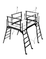
かかる可搬式作業台には種々のタイプがあるが、例えば図10に示すように対向する梯子状の主脚1の間に天板2を掛け渡したものがあり、このタイプのものは図10のように単独での使用もできるが、図11に示すように複数個を縦横方向に連結してステージとすることもできる。
There are various types of such portable worktables. For example, as shown in FIG. 10, there is one in which a
このような可搬式作業台を使用する場合、天板2上で作業する際の転落を防止するため、天板2の長さ方向の側部には四角形の枠状の補助手摺3を取り付けている。しかし、天板2の妻側である主脚1からの昇降面側は、昇降の妨げになることから通常は手摺のような転落防止手段を特に設けることはしていない。
When such a portable worktable is used, a rectangular frame-shaped
なお、図12に示すようにステージとして使用する場合には、おおきな開放面が形成される妻側の端部には必要に応じて枠状の補助手摺21,22を取り付けることもある。この補助手摺21は門型であり、補助手摺22は正方形である。
In addition, when using as a stage as shown in FIG. 12, the frame-shaped
また、図13に示すように主脚1を傾斜させてハ字形に対向させ、主脚1の上部分に踏み板4を設けた可搬式作業台もあり、この可搬式作業台を2台、間隔をおいて対向させ、この間に天板2を配設して使用するものもある。
In addition, as shown in FIG. 13, there is a portable work table in which the
この図13に示すようなタイプの可搬式作業台においても、天板2の長さ方向の側部からの転落を防止するために、この側に前記図10、図11に示したものと同様の四角形状の枠状の補助手摺3を設けることもあるが、かかる場合は、主脚1が傾斜しているため、主脚1と補助手摺3との間に隙間が生じ、この隙間からの転落のおそれがある。
Also in the portable work table of the type as shown in FIG. 13, in order to prevent the
そこで、図13に示すタイプの可搬式作業台の場合は、四角形状の枠状の補助手摺3を使用せずに、主脚1の傾斜に対応させて側部の縦桟を斜めに取り付けた台形状の枠に形成した補助手摺23を別途格別に用意し、これを取り付けている。
Therefore, in the case of the portable work table of the type shown in FIG. 13, the side bars are attached obliquely corresponding to the inclination of the
前記従来技術は当業者間で一般的に行われているものであり、文献公知発明にかかるものではない。 The prior art is generally performed by those skilled in the art, and is not related to a known invention.
前記図10、図11に示すように昇降面側に手摺を取り付けない場合は当然のことながら転落の危険性が大きい。また、図12のように開放面側に補助手摺21,22を取り付ければ転落を防止できるが、大きな開放面を塞ぐには、異なる2種類の補助手摺21,22を必要とし、しかもその取り付け作業には時間と手間を有する。このため、かかる補助手摺21,22を昇降面側の開放面にしようするのは困難である。
As shown in FIGS. 10 and 11, when the handrail is not attached to the lifting surface side, the risk of falling is naturally large. In addition, if the
また、図13のように格別の補助手摺23を別途用意するのは、コスト高となり、在庫管理も容易ではない。
Further, separately preparing a special
本発明の目的は前記従来例の不都合を解消し、対向する梯子状の主脚の間に天板を掛け渡したタイプのものや、主脚を傾斜させてハ字形に対向させ、主脚の上部分に踏み板を設けたタイプの可搬式作業台、いずれのものにでも、また、単独で使用する場合、複数を組み合わせて使用する場合のいずれの場合でも、昇降側の開放面を簡単に開閉でき、既設の作業台への取り付けも容易で使い勝手のよい可搬式作業台の手摺部材を提供することにある。 The object of the present invention is to eliminate the disadvantages of the conventional example described above, such as a type in which a top plate is spanned between opposing ladder-shaped main legs, or by tilting the main legs so that they face each other in a C shape. Easily open and close the open side on the lift side for any type of portable workbench with a treadle on the top, whether used alone or in combination. It is possible to provide a handrail member for a portable work table that can be easily attached to an existing work table and is easy to use.
本発明は前記目的を達成するものとして、請求項1記載の発明は、主脚の上部に天板を設け、天板への昇降面を開放面に形成し、非昇降面側に手摺などの突出部材を設けてある可搬式作業台に取り付ける手摺部材であって、前記手摺部材をバー形状に形成し、この手摺部材を天板への昇降面を開閉するように水平方向に回動自在に前記突出部材に取り付けたことを要旨とするものである。 In order to achieve the above object, the present invention is characterized in that the top plate of the main leg is provided with a top plate, a lift surface to the top plate is formed as an open surface, and a handrail is provided on the non-lift surface side. A handrail member attached to a portable work bench provided with a projecting member, wherein the handrail member is formed in a bar shape, and the handrail member can be rotated in a horizontal direction so as to open and close a lifting surface to the top plate. The gist is that it is attached to the protruding member.
請求項2記載の発明は、前記手摺部材は、非昇降面側に配設してある既存の手摺などの突出部分に取り付け可能な取付金具に固定される角度設定金具に回動自在に取り付けられることを要旨とするものである。 According to a second aspect of the present invention, the handrail member is rotatably attached to an angle setting bracket that is fixed to a mounting bracket that can be attached to a protruding portion such as an existing handrail disposed on the non-elevating surface side. This is the gist.
請求項3記載の発明は、前記角度設定金具は、手摺部材を所定の角度に固定できる係止ピンと異なる角度に形成した複数の切欠きとを備えることを要旨とするものである。
The gist of the invention described in
請求項1記載の本発明によれば、既存の可搬式作業台に備わっている非昇降面側の手摺などの突出部材にバー形状の手摺部材が回動自在に取り付けられるから、これを回動するだけで昇降面を簡単に開閉でき、昇降面側からの転落などの危険を簡単な構造および操作で容易に回避できる。 According to the first aspect of the present invention, since the bar-shaped handrail member is rotatably attached to the protruding member such as the handrail on the non-elevating / lowering surface side provided in the existing portable workbench, it is rotated. Thus, the lifting surface can be easily opened and closed, and the danger of falling from the lifting surface side can be easily avoided with a simple structure and operation.
請求項2記載の本発明によれば、手摺部材は、取付金具で既存の突出部材に簡単に取り付けられ、また、角度固定金具で簡単に取付角度を変更できるから、容易に昇降面を開閉できる。 According to the second aspect of the present invention, the handrail member can be easily attached to the existing protruding member by the mounting bracket, and the mounting angle can be easily changed by the angle fixing bracket, so that the lifting surface can be easily opened and closed. .
請求項3記載の本発明によれば、異なる角度に形成した複数の切欠きのうちのいずれかを選択し、この切欠きに係止ピンを係止するだけの簡単な操作で手摺部材を所望の角度位置に固定できる。 According to the third aspect of the present invention, a handrail member is desired by a simple operation of selecting any one of a plurality of notches formed at different angles and locking a locking pin in the notches. Can be fixed at any angular position.
以上述べたように本発明の可搬式作業台の手摺部材は、対向する梯子状の主脚の間に天板を掛け渡したタイプのものや、主脚を傾斜させてハ字形に対向させ、主脚1の上部分に踏み板を設けたタイプの可搬式作業台、いずれのものにでも、また、単独で使用する場合、複数を組み合わせて使用する場合のいずれの場合でも、突出部材に簡単に取り付けて昇降側の開放面を容易に開閉でき、開放面からの転落を防止し安全性の向上を図ることができ、既設の作業台への取り付けも容易で使い勝手のよいものである。
As described above, the handrail member of the portable workbench of the present invention is of a type in which a top plate is spanned between opposing ladder-shaped main legs, or the main legs are inclined to face each other in a C shape, A portable workbench of the type that has a footboard on the upper part of the
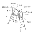
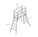
以下、図面について本発明の実施形態を詳細に説明する。図1は本発明の可搬式作業台の手摺部材の実施形態を示す斜視図で、可搬式作業台の構造としては、間隔をおいて対向させて配置した梯子状の主脚1,1の間に天板2を掛け渡し、この天板2の長さ方向の側部には横桟3aと縦桟3bの組み合わせによる長方形の枠状の補助手摺3を立設し、また、主脚1から天板2への昇降面側である天板2の妻側の両側には手掛け棒5を立設してある。
Hereinafter, embodiments of the present invention will be described in detail with reference to the drawings. FIG. 1 is a perspective view showing an embodiment of a handrail member of a portable workbench according to the present invention. The portable workbench has a structure between ladder-shaped
このような構造の可搬式作業台において、バー状の手摺部材6を前記補助手摺3の上部角部すなわち横桟3aと縦桟3bとの交差部に水平方向に回動自在に取り付けた。バー状の手摺部材6の長さは、天板2の幅方向の長さ、すなわち主脚1から天板2への昇降面9の開口幅にほぼ等しく形成する。
In the portable work table having such a structure, the bar-
この手摺部材6を開口面9に取り付ける手段は、補助手摺3の上部の角部を固定する取付金具8と、この取付金具8の上部に取り付ける角度設定金具7とで構成する。
The means for attaching the
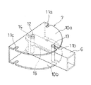
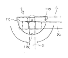
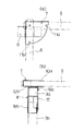
角度設定金具7は、図3〜図6に示すように上下に、バー状の手摺部材6の幅にほぼ等しい幅の間隔をおいて配置した平面半円形状の角度設定板10a,10bを本体とし、この角度設定板10a,10bの円弧状部の周縁に90度間隔で3個のスリット11a,11b,11cを形成する。
As shown in FIGS. 3 to 6, the angle
そして、上下の角度設定板10a,10bの間にバー状の手摺部材6の端部を水平方向に回動自在に挿入する。
Then, the end of the bar-
また、角度設定板10a,10bの直線状部の側寄りに上下の角度設定板10a,10bの間に固定ピン12を立設し、一方、手摺部材6に前記スリット11a,11b,11cに選択的に着脱自在に挿入する係止ピン13を立設するとともに、前記固定ピン12が上下方向に挿通する長孔14を穿設し、固定ピン12と係止ピン13との間にバネ15を弾装する。長孔14の長さはスリット11a〜11cの長さとほぼ等しく形成する。
Further, a
これにより、手摺部材6は、長孔14の長さ分だけスライド自在で、かつ、固定ピン12位置を中心軸として角度設定板10a,10bの円弧状部に沿って回動自在に角度設定金具7に取り付けられる。なお、図5に示す例では、90度間隔で2個のスリット11a,11bを形成した。
Thereby, the
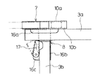
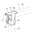
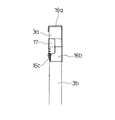
取付金具8は図5〜図9に示すように補助手摺3の横桟3aと縦桟3bに固定される本体部16と、縦桟3bに固定される固定片17とで構成し、本体部16は図7〜図9に示すように横桟3aの上面にかぶさるようにして係止するL字形のフック部16aと、その下方に連続して垂設されて縦桟3bの側部にはまり込むコ字形の係止部16bとで構成する。
As shown in FIGS. 5 to 9, the
固定片17は平面L字形に形成したもので、前記係止部16bの一方の端部に外側に直角に突設した取付片16cに回動自在に設けたもので、L字形の一方の片を縦桟3bと平行に配置し、この片が縦桟3bの側面に摺接する。
The
次に前記取付金具8と角度設定金具7を使用して手摺部材6を補助手摺3の上部角部に取り付ける方法を説明する。まず、取付金具8を補助手摺3に取り付けるが、係止部16bを縦桟3bの側部にあてがい、フック部16aを横桟3aの上面に被せ、この状態で固定片17を縦桟3bの方向に回動してこれを縦桟3bの側部に摺接する。これにより、縦桟3bは固定片17と係止部16bとで両側から挟み込まれた状態となり、同時に上桟3aはフック部16aで押えられた状態となって、取付金具8が補助手摺3に固定される。
Next, a method of attaching the
かかる取付金具8の上に、手摺部材6を取り付けた角度設定金具7を固定する。これにより、手摺部材6が補助手摺3に180度回動自在に取り付けら、天板2への昇降面9に開閉自在に配置される。
On this mounting
そして、天板2の妻部側からの落下を防止するために、図1に示すように昇降面9を手摺部材6で閉塞したい場合は、図4において、中央位置のスリット11bに係止ピン13を挿入した状態とすれば、手摺部材6は補助手摺3と直交する方向(90度の位置)に配置されて昇降面9が閉鎖される。
And in order to prevent the elevating surface 9 from being closed by the
天板2への昇降時に、昇降面9を通過するには、手摺部材6を持ってこれをバネ15の弾力に抗して長さ方向に引っ張れば、係止ピン13がスリット11bから抜ける。このとき、手摺部材6は長孔14の長さ分外側に移動するから、手摺部材6に取り付けてある係止ピン13もスリット11bにそってその分だけ外側に移動する。
In order to pass through the lifting surface 9 when moving up and down to the
よって、手摺部材6を固定ピン12を中心軸にしてスリット11aまたはスリット11cの方向に回動し、バネ15の弾力を利用して係止ピン13をスリット11aまたはスリット11cに挿入すれば、手摺部材6は補助手摺3に対して0度の位置または180度の位置に係止され、補助手摺3と平行にその内側に重合する状態となり、または、補助手摺3の外側延長上に配置される状態となって、昇降面9から除かれ、昇降面9が開放される。
Therefore, if the
このようにして天板2から主脚1に降りるには、手摺部材6を180度の位置に開き開放された昇降面9を通過した後は、前記と逆の操作で手摺部材6を回動すれば、手摺部材6を90度の位置に戻すことができ昇降面9を再度閉じることができる。また、天板2に上るときは、手摺部材6を0度または180度の位置に回動して昇降面9を開放し、天板2に載ったならば手摺部材6を再度回動して90度の位置に戻し、昇降面9を閉じて天板2からの脱落防止部材とする。
In order to descend from the
なお、スリットの形成部位は、前記のような90度間隔に限定されるものではなく、任意の角度に設定可能である。 In addition, the formation part of a slit is not limited to the above 90 degree | times intervals, It can set to arbitrary angles.
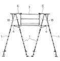
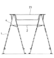
図2は、主脚1を傾斜させてハ字形に対向させ、主脚1の上部分に踏み板4を設けた可搬式作業台もあり、この可搬式作業台を2台、間隔をおいて対向させ、この間に天板2を配設して使用する場合に実施するもので、かかる場合は天板2の長さ方向の側部には図1の例で使用するものと同様の補助手摺3を取り付け、さらにこの補助手摺3に前記と同様にして取付固定8と角設定金具7とで手摺部材6を取り付ける。
FIG. 2 also shows a portable work table in which the
この場合、主脚1が傾斜していることから、補助手摺3の端部と主脚1の上部との間には大きな隙間18が生じるが、手摺部材6を補助手摺3に対して180度の位置に開いて配設することで、隙間18の部分に手摺部材6が介在することになる。よって、この隙間18からの墜落防止を図ることができる。
In this case, since the
1 主脚 2 天板
3 補助手摺 3a 横桟
3b 縦桟 4 踏み板
5 手掛け棒 6 手摺部材
7 角度設定金具 8 取付金具
9 昇降面 10a,10b 角度設定板
11a,11b,11c スリット
12 固定ピン 13 係止ピン
14 長孔 15 バネ
16 本体部 16a フック部
16b 係止部 16c 取付片
17 固定片 18 隙間
21,22,23 補助手摺
DESCRIPTION OF
Claims (3)
Priority Applications (1)
| Application Number | Priority Date | Filing Date | Title |
|---|---|---|---|
| JP2004105486A JP4190452B2 (en) | 2004-03-31 | 2004-03-31 | Portable handrail |
Applications Claiming Priority (1)
| Application Number | Priority Date | Filing Date | Title |
|---|---|---|---|
| JP2004105486A JP4190452B2 (en) | 2004-03-31 | 2004-03-31 | Portable handrail |
Publications (2)
| Publication Number | Publication Date |
|---|---|
| JP2005290763A true JP2005290763A (en) | 2005-10-20 |
| JP4190452B2 JP4190452B2 (en) | 2008-12-03 |
Family
ID=35324012
Family Applications (1)
| Application Number | Title | Priority Date | Filing Date |
|---|---|---|---|
| JP2004105486A Expired - Lifetime JP4190452B2 (en) | 2004-03-31 | 2004-03-31 | Portable handrail |
Country Status (1)
| Country | Link |
|---|---|
| JP (1) | JP4190452B2 (en) |
Cited By (10)
| Publication number | Priority date | Publication date | Assignee | Title |
|---|---|---|---|---|
| JP2007321350A (en) * | 2006-05-30 | 2007-12-13 | Gop Kk | Portable work platform and handrail member |
| JP2008255586A (en) * | 2007-04-02 | 2008-10-23 | Gop Kk | Handrail member of portable working platform |
| JP2011094378A (en) * | 2009-10-29 | 2011-05-12 | Alinco Inc | Working position sensor in workbench |
| JP2012092617A (en) * | 2010-10-28 | 2012-05-17 | Alinco Inc | Work bench |
| GB2487737A (en) * | 2011-02-01 | 2012-08-08 | Teletower Com Ltd | Guardrail for an elevated working platform |
| JP2012225035A (en) * | 2011-04-19 | 2012-11-15 | Gop Kk | Stepladder type workbench |
| JP2013209803A (en) * | 2012-03-30 | 2013-10-10 | Sanki Eng Co Ltd | Portable workbench |
| GB2503702A (en) * | 2012-07-04 | 2014-01-08 | Teletower Com Ltd | Side protection for collapsible working platform |
| JP2014009562A (en) * | 2012-07-03 | 2014-01-20 | Nikko Co Ltd | Openable handrail for temporary scaffold |
| JP2017014744A (en) * | 2015-06-29 | 2017-01-19 | 旭化成ホームズ株式会社 | Suspending work floor |
-
2004
- 2004-03-31 JP JP2004105486A patent/JP4190452B2/en not_active Expired - Lifetime
Cited By (13)
| Publication number | Priority date | Publication date | Assignee | Title |
|---|---|---|---|---|
| JP2007321350A (en) * | 2006-05-30 | 2007-12-13 | Gop Kk | Portable work platform and handrail member |
| JP2008255586A (en) * | 2007-04-02 | 2008-10-23 | Gop Kk | Handrail member of portable working platform |
| JP2011094378A (en) * | 2009-10-29 | 2011-05-12 | Alinco Inc | Working position sensor in workbench |
| JP2012092617A (en) * | 2010-10-28 | 2012-05-17 | Alinco Inc | Work bench |
| GB2487737B (en) * | 2011-02-01 | 2013-05-01 | Teletower Com Ltd | Guardrail for an elevated working platform |
| GB2487737A (en) * | 2011-02-01 | 2012-08-08 | Teletower Com Ltd | Guardrail for an elevated working platform |
| JP2014507578A (en) * | 2011-02-01 | 2014-03-27 | テレタワー.コム リミテッド | Protective rail for aerial work platform |
| JP2012225035A (en) * | 2011-04-19 | 2012-11-15 | Gop Kk | Stepladder type workbench |
| JP2013209803A (en) * | 2012-03-30 | 2013-10-10 | Sanki Eng Co Ltd | Portable workbench |
| JP2014009562A (en) * | 2012-07-03 | 2014-01-20 | Nikko Co Ltd | Openable handrail for temporary scaffold |
| GB2503702A (en) * | 2012-07-04 | 2014-01-08 | Teletower Com Ltd | Side protection for collapsible working platform |
| GB2503702B (en) * | 2012-07-04 | 2017-01-18 | Teletower Com Ltd | Knee height guardrail for an elevated working platform |
| JP2017014744A (en) * | 2015-06-29 | 2017-01-19 | 旭化成ホームズ株式会社 | Suspending work floor |
Also Published As
| Publication number | Publication date |
|---|---|
| JP4190452B2 (en) | 2008-12-03 |
Similar Documents
| Publication | Publication Date | Title |
|---|---|---|
| JP5364241B2 (en) | Handrail for portable worktable | |
| JP4190452B2 (en) | Portable handrail | |
| KR102186318B1 (en) | Equipment for installing top-down type segmental ladder and top-down type segmental ladder | |
| KR101783215B1 (en) | Safety board for architecture | |
| JP2009057198A (en) | Elevator car, assembly method of elevator car, and lifting tool | |
| KR102503283B1 (en) | Workbench for clean room | |
| JP4843381B2 (en) | Portable worktable and handrail member | |
| JP3180629U (en) | Stepladder platform | |
| JP6645766B2 (en) | Stepladder work table | |
| JP4761843B2 (en) | Portable worktable | |
| KR101672410B1 (en) | Handrail safety device and stair type movable platform | |
| JP5170557B2 (en) | Temporary scaffolding staircase frame | |
| JP6254847B2 (en) | Stepladder platform | |
| JP7429074B2 (en) | Workbench | |
| JP3125537U (en) | Portable worktable | |
| JP2009228364A (en) | Fittings | |
| JP5863716B2 (en) | Rack and method of using the same | |
| JP5963829B2 (en) | Temporary scaffolding staircase frame | |
| JP4072581B2 (en) | Scaffolding equipment | |
| JP4624609B2 (en) | Scaffolding board | |
| JP2011038306A (en) | Fall prevention implement of building scaffold | |
| JP2017160637A (en) | Handrail frame and lifting mobile scaffold | |
| JP6830777B2 (en) | Mounting stand | |
| KR100752389B1 (en) | Frame Scaffolding Handrail | |
| KR20240164149A (en) | A building safety platform |
Legal Events
| Date | Code | Title | Description |
|---|---|---|---|
| A621 | Written request for application examination |
Free format text: JAPANESE INTERMEDIATE CODE: A621 Effective date: 20070201 |
|
| A977 | Report on retrieval |
Free format text: JAPANESE INTERMEDIATE CODE: A971007 Effective date: 20080423 |
|
| A131 | Notification of reasons for refusal |
Free format text: JAPANESE INTERMEDIATE CODE: A131 Effective date: 20080513 |
|
| A521 | Request for written amendment filed |
Free format text: JAPANESE INTERMEDIATE CODE: A523 Effective date: 20080709 |
|
| TRDD | Decision of grant or rejection written | ||
| A01 | Written decision to grant a patent or to grant a registration (utility model) |
Free format text: JAPANESE INTERMEDIATE CODE: A01 Effective date: 20080819 |
|
| A01 | Written decision to grant a patent or to grant a registration (utility model) |
Free format text: JAPANESE INTERMEDIATE CODE: A01 |
|
| A61 | First payment of annual fees (during grant procedure) |
Free format text: JAPANESE INTERMEDIATE CODE: A61 Effective date: 20080916 |
|
| FPAY | Renewal fee payment (event date is renewal date of database) |
Free format text: PAYMENT UNTIL: 20110926 Year of fee payment: 3 |
|
| R150 | Certificate of patent or registration of utility model |
Ref document number: 4190452 Country of ref document: JP Free format text: JAPANESE INTERMEDIATE CODE: R150 Free format text: JAPANESE INTERMEDIATE CODE: R150 |
|
| FPAY | Renewal fee payment (event date is renewal date of database) |
Free format text: PAYMENT UNTIL: 20120926 Year of fee payment: 4 |
|
| R250 | Receipt of annual fees |
Free format text: JAPANESE INTERMEDIATE CODE: R250 |
|
| FPAY | Renewal fee payment (event date is renewal date of database) |
Free format text: PAYMENT UNTIL: 20130926 Year of fee payment: 5 |
|
| R250 | Receipt of annual fees |
Free format text: JAPANESE INTERMEDIATE CODE: R250 |
|
| R250 | Receipt of annual fees |
Free format text: JAPANESE INTERMEDIATE CODE: R250 |
|
| R250 | Receipt of annual fees |
Free format text: JAPANESE INTERMEDIATE CODE: R250 |
|
| R250 | Receipt of annual fees |
Free format text: JAPANESE INTERMEDIATE CODE: R250 |
|
| R250 | Receipt of annual fees |
Free format text: JAPANESE INTERMEDIATE CODE: R250 |
|
| R250 | Receipt of annual fees |
Free format text: JAPANESE INTERMEDIATE CODE: R250 |
|
| EXPY | Cancellation because of completion of term |