JP2005290816A - Roof decorative panel fitting - Google Patents
Roof decorative panel fitting Download PDFInfo
- Publication number
- JP2005290816A JP2005290816A JP2004106731A JP2004106731A JP2005290816A JP 2005290816 A JP2005290816 A JP 2005290816A JP 2004106731 A JP2004106731 A JP 2004106731A JP 2004106731 A JP2004106731 A JP 2004106731A JP 2005290816 A JP2005290816 A JP 2005290816A
- Authority
- JP
- Japan
- Prior art keywords
- receiving member
- decorative panel
- panel
- roof decorative
- mounting bracket
- Prior art date
- Legal status (The legal status is an assumption and is not a legal conclusion. Google has not performed a legal analysis and makes no representation as to the accuracy of the status listed.)
- Granted
Links
- 239000000463 material Substances 0.000 claims abstract description 9
- 230000003014 reinforcing effect Effects 0.000 claims description 10
- 230000002093 peripheral effect Effects 0.000 claims description 9
- 238000010276 construction Methods 0.000 description 4
- 230000000630 rising effect Effects 0.000 description 4
- 230000008878 coupling Effects 0.000 description 2
- 238000010168 coupling process Methods 0.000 description 2
- 238000005859 coupling reaction Methods 0.000 description 2
- 238000005452 bending Methods 0.000 description 1
- 238000010586 diagram Methods 0.000 description 1
- 230000000694 effects Effects 0.000 description 1
- 239000002184 metal Substances 0.000 description 1
- 238000004806 packaging method and process Methods 0.000 description 1
- 229920003002 synthetic resin Polymers 0.000 description 1
- 239000000057 synthetic resin Substances 0.000 description 1
Images

Landscapes
- Roof Covering Using Slabs Or Stiff Sheets (AREA)
Abstract
Description
本発明は、屋根の軒先、ケラバ等に設けられる屋根化粧パネルを取付けるための屋根化粧パネル取付金具に関する。 The present invention relates to a roof decorative panel mounting bracket for mounting a roof decorative panel provided on a roof eave, a keraba or the like.
従来、折板屋根などの軒先やケラバには、屋根化粧パネル取付金具によって屋根化粧パネルを取り付けており、この屋根化粧パネル取付金具は、屋根材に固着して取付けられる取付部材と、この取付部材に略直交する方向に固定して連結されたパネル受部材とを組み合わせて構成している。(例えば、特許文献1参照。)。 Conventionally, a roof decorative panel is attached to an eaves or a keraba such as a folded-plate roof by a roof decorative panel mounting bracket. The roof decorative panel mounting bracket is attached to a roof material, and the mounting member. And a panel receiving member that is fixedly connected in a direction substantially orthogonal to each other. (For example, refer to Patent Document 1).
この屋根化粧パネル取付金具の使用に際しては、例えば、屋根の適所にボルト、ナット等で上記取付部材を固定し、次いで、上記取付部材の先端に上記パネル受部材を略鉛直方向に位置付けたうえで、ボルト、ナット等の連結具を締め付けて、上記取付部材の先端に上記パネル受部材を連結させて固定する。 When using this roof decorative panel mounting bracket, for example, the mounting member is fixed with bolts, nuts, etc. at appropriate positions on the roof, and then the panel receiving member is positioned in a substantially vertical direction at the tip of the mounting member. The panel receiving member is connected and fixed to the tip of the mounting member by tightening a connecting tool such as a bolt or a nut.
そして、この鉛直方向に固定されたパネル受部材に、上記屋根化粧パネルを被覆させて係止させ、屋根の軒先、ケラバ等に屋根化粧パネルを取付けるのである。
しかし、この屋根化粧パネル取付金具では、以下の問題があった。 However, this roof decorative panel mounting bracket has the following problems.
すなわち、屋根化粧パネル取付金具は、パネル受部材と、取付部材と、これらを連結するボルト、ナット等の連結具とで構成されているが、各々の部材を仮組みせずに、作業現場に搬送し、これを高所の作業現場で一々組み立てて使用することは、危険であるうえ、非常に手間を要するという問題があった。 That is, the roof decorative panel mounting bracket is composed of a panel receiving member, a mounting member, and a connecting tool such as a bolt and a nut for connecting these, but without temporarily assembling each member, Conveying and assembling and using them one by one at work sites in high places is dangerous and very troublesome.
一方、この問題を回避するため、各々の部材を仮組み状態で搬送することも可能である。 On the other hand, in order to avoid this problem, each member can be transported in a temporarily assembled state.
ところが、この仮組み状態のままでは、パネル受部材と、取付部材とをコンパクトに折り畳むことができないため、搬送時に大型化となり、持ち運びが不便なうえ、輸送コストも増すという問題があった。 However, in this temporarily assembled state, the panel receiving member and the mounting member cannot be folded in a compact manner, resulting in an increase in size during transportation, inconvenience for carrying, and an increase in transportation cost.
しかも、この仮組み状態では、上記パネル部材が輸送中などの衝撃によって、損傷する危険や、ガタツキを生じ易いとい問題もあった。 In addition, in this temporarily assembled state, there is a problem that the panel member is easily damaged due to an impact during transportation or the like, and rattling is likely to occur.
本発明は、かかる課題を解決することを目的とするもので、仮組み状態であっても、折り畳んでコンパクトに搬送できるうえ、搬送中の損傷やガタツキを防止できる屋根化粧パネル取付金具を提供する。 The present invention aims to solve such problems, and provides a roof decorative panel mounting bracket that can be folded and transported in a compact manner even in a temporarily assembled state, and can prevent damage and rattling during transportation. .
上記目的を達成するため、
請求項1に係る屋根化粧パネル取付金具は、屋根化粧パネルを取付けるためのパネル受部材と、屋根材に取付ける取付部材とを連結具で回転自在に連結し、これらパネル受部材と取付部材が、起立又は折畳可能に構成された屋根化粧パネル取付金具において、上記取付部材には、上記パネル受部材を折畳んだときに、このパネル受部材の一片を収容するスリット開口を形成したことを特徴とする。
To achieve the above objective,
The roof decorative panel mounting bracket according to claim 1, the panel receiving member for mounting the roof decorative panel and the mounting member to be mounted on the roof material are rotatably connected by a connector, and the panel receiving member and the mounting member are In the roof decorative panel mounting bracket configured to be able to stand or fold, the mounting member is formed with a slit opening that accommodates a piece of the panel receiving member when the panel receiving member is folded. And
このものでは、取付部材に、パネル受部材の一片を収容するスリット開口を形成しているので、仮組み状態であっても、連結具を回転軸にして、パネル受部材を取付部材に重合させて折畳み収納することができ、搬送時に小型化となり、持ち運びが便利なうえ、輸送コストをも削減できる。 In this case, since the slit opening for accommodating one piece of the panel receiving member is formed in the mounting member, the panel receiving member is superposed on the mounting member with the coupling tool as the rotation axis even in the temporarily assembled state. It can be folded and stored, miniaturized during transportation, convenient to carry, and can reduce transportation costs.
請求項2に係る屋根化粧パネル取付金具は、請求項1において、上記スリット開口の周縁には、内方に向けて突出された補強用リブを形成したことを特徴とする。 A roof decorative panel mounting bracket according to a second aspect is characterized in that, in the first aspect, a reinforcing rib projecting inward is formed on the periphery of the slit opening.
このものでは、内方に向けて突出された補強用リブを形成することで、パネル受部材を取付部材に重合させて折畳み収納することができるうえ、スリット開口部分の強度を高め、且つ、取付部材全体に剛性を高め、搬送中における損傷を防止できる。 In this case, by forming a reinforcing rib protruding inward, the panel receiving member can be folded and stored on the mounting member, and the strength of the slit opening portion can be increased and mounted. The rigidity of the entire member can be increased and damage during transportation can be prevented.
請求項3に係る屋根化粧パネル取付金具は、請求項1又は2の何れかにおいて、上記スリット開口の周端縁には、内側に向けて膨出された凸部を形成したことを特徴とする。 A roof decorative panel mounting bracket according to a third aspect of the present invention is characterized in that, in any one of the first and second aspects, a convex portion bulging inward is formed at a peripheral edge of the slit opening. .
このものでは、スリット開口の周端縁には、内側に向けて膨出された凸部を形成しているので、パネル受部材を取付部材に重合させて折畳み収納した後は、上記凸部がパネル受部材に圧接して保持して、輸送中などの衝撃におけるガタツキを防止できる。 In this case, since the convex portion bulged inward is formed on the peripheral edge of the slit opening, the convex portion is formed after the panel receiving member is overlapped with the mounting member and folded and stored. By holding the panel receiving member in pressure contact, it is possible to prevent rattling during impacts during transportation.
請求項4に係る屋根化粧パネル取付金具は、請求項3において、上記凸部の先端は、半球状に形成したことを特徴とする。 A roof decorative panel mounting bracket according to a fourth aspect is characterized in that, in the third aspect, the tip of the convex portion is formed in a hemispherical shape.
このものでは、請求項3における凸部の先端を半球状に形成しているので、パネル受部材をスムーズに折畳んで収納できるうえ、収納時に取付部材の傷付きも防止できる。
In this case, since the tip of the convex portion in
請求項5に係る屋根化粧パネル取付金具は、請求項1〜4の何れかにおいて、上記スリット開口は、開放側から閉止側に向けて、徐々に狭くなるテーパー状に形成したことを特徴とする。 The roof decorative panel mounting bracket according to claim 5 is characterized in that in any one of claims 1 to 4, the slit opening is formed in a tapered shape gradually narrowing from the open side to the closed side. .
このものでは、スリット開口が開放側から閉止側に向けて、徐々に狭くなるテーパー状に形成しているので、パネル受部材をスムーズに嵌入できると共に、このパネル受部材を取付部材に重合させて折畳み収納した後は、上記スリット開口がパネル受部材に噛合して保持し、輸送中などの衝撃におけるガタツキを防止できる。また、収納時に取付部材の傷付きも防止できる。 In this case, since the slit opening is formed in a tapered shape gradually narrowing from the open side to the closed side, the panel receiving member can be smoothly inserted and the panel receiving member is superposed on the mounting member. After folding and storing, the slit opening is engaged with and held by the panel receiving member, and it is possible to prevent rattling in an impact such as during transportation. In addition, the mounting member can be prevented from being damaged during storage.
請求項6に係る屋根化粧パネル取付金具は、請求項1〜5の何れかにおいて、上記スリット開口は、間隔をあけて複数形成したことを特徴とする。 A roof decorative panel mounting bracket according to a sixth aspect of the present invention is characterized in that in any one of the first to fifth aspects, a plurality of the slit openings are formed at intervals.
このものでは、スリット開口は間隔をあけて複数形成しているので、所望の位置で、パネル受部材を取付部材に重合させて折畳み収納することができる。 In this case, since a plurality of slit openings are formed at intervals, the panel receiving member can be overlapped with the attachment member and folded and stored at a desired position.
本発明によれば、次のような効果がある。
請求項1に係る屋根化粧パネル取付金具によれば、取付部材に、パネル受部材の一片を収容するスリット開口を形成しているので、仮組み状態であっても、連結具を回転軸にして、パネル受部材を取付部材に重合させて折畳み収納することができ、搬送時に小型化となり、持ち運びが便利なうえ、輸送コストをも削減できる。
The present invention has the following effects.
According to the roof decorative panel mounting bracket according to claim 1, since the slit opening that accommodates one piece of the panel receiving member is formed in the mounting member, even in the temporarily assembled state, the coupling tool is used as the rotation axis. In addition, the panel receiving member can be folded and stored on the mounting member, so that it can be miniaturized during transportation, convenient to carry, and transport costs can be reduced.
請求項2に係る屋根化粧パネル取付金具によれば、内方に向けて突出された補強用リブを形成することで、パネル受部材を取付部材に重合させて折畳み収納することができるうえ、スリット開口部分の強度を高め、且つ、取付部材全体に剛性を高め、搬送中における損傷を防止できる。
According to the roof decorative panel mounting bracket according to
請求項3に係る屋根化粧パネル取付金具によれば、スリット開口の周端縁には、内側に向けて膨出された凸部を形成しているので、パネル受部材を取付部材に重合させて折畳み収納した後は、上記凸部がパネル受部材に圧接して保持して、輸送中などの衝撃におけるガタツキを防止できる。
According to the roof decorative panel mounting bracket according to
請求項4に係る屋根化粧パネル取付金具によれば、請求項3における凸部の先端を半球状に形成しているので、パネル受部材をスムーズに折畳んで収納できるうえ、収納時に取付部材の傷付きも防止できる。
According to the roof decorative panel mounting bracket according to claim 4, since the tip of the convex portion in
請求項5に係る屋根化粧パネル取付金具によれば、スリット開口が開放側から閉止側に向けて、徐々に狭くなるテーパー状に形成しているので、パネル受部材をスムーズに嵌入できると共に、このパネル受部材を取付部材に重合させて折畳み収納した後は、上記スリット開口がパネル受部材に噛合して保持し、輸送中などの衝撃におけるガタツキを防止できる。また、収納時に取付部材の傷付きも防止できる。 According to the roof decorative panel mounting bracket according to claim 5, since the slit opening is formed in a tapered shape gradually narrowing from the open side to the closed side, the panel receiving member can be smoothly inserted, and this After the panel receiving member is overlapped with the mounting member and folded and stored, the slit opening is held in mesh with the panel receiving member, thereby preventing rattling during impacts such as during transportation. In addition, the mounting member can be prevented from being damaged during storage.
請求項6に係る屋根化粧パネル取付金具によれば、スリット開口は間隔をあけて複数形成しているので、所望の位置で、パネル受部材を取付部材に重合させて折畳み収納することができる。 According to the roof decorative panel mounting bracket according to the sixth aspect, since a plurality of slit openings are formed at intervals, the panel receiving member can be overlapped with the mounting member and folded and stored at a desired position.
以下、本発明に係る屋根化粧パネル取付金具Aを図面に基づき説明する。 Hereinafter, the roof decorative panel mounting bracket A according to the present invention will be described with reference to the drawings.
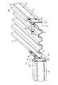
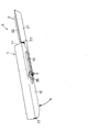
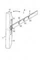
図1は、本発明に係る屋根化粧パネル取付金具の一実施例を示す使用状態図、図2は、本発明に係る屋根化粧パネル取付金具の一実施例を示す起立状態の斜視図、図3は、図2の折畳み収納した状態を示す斜視図である。 FIG. 1 is a use state diagram showing an embodiment of a roof decorative panel mounting bracket according to the present invention, FIG. 2 is a perspective view of a standing state showing an embodiment of a roof decorative panel mounting bracket according to the present invention, and FIG. FIG. 3 is a perspective view showing a state in which the folded storage of FIG.
この屋根化粧パネル取付金具Aは、屋根化粧パネルPを取付けるためのパネル受部材1と、このパネル受部材1を屋根材Yに固定するための取付部材2とを、ボルト、ナットなどの連結具3で連結されて成る。
The roof decorative panel mounting bracket A includes a panel receiving member 1 for attaching the roof decorative panel P and an attaching
屋根化粧パネルPは、従来同様、金属板、合成樹脂板等で形成されており、その上下端には、パネル受部材1に係止される上、下折縁P1を形成している。 The roof decorative panel P is formed of a metal plate, a synthetic resin plate, or the like as in the prior art, and the upper and lower ends of the roof decorative panel P are locked to the panel receiving member 1 and have a lower folding edge P1.
パネル受部材1は、屋根化粧パネルPに応じて、これを取付可能な形状であれば良いが、本実施例では、屋根化粧パネルPの上、下折縁P1を係止するために、両端面に屋根化粧パネルPの上、下折縁P1を受止固定する受止折曲片11を形成している。
The panel receiving member 1 only needs to have a shape that allows the panel receiving member 1 to be attached to the roof decorative panel P. In this embodiment, both ends of the panel receiving member 1 are used to lock the lower folding edge P1 on the roof decorative panel P. A receiving
また、パネル受部材1の側面には、長手方向に向けて片部12を形成しており、この片部12には、取付け高さを調節するための長孔13を、略中央から一端側に向けて形成している。
Further, a
取付部材2は、屋根材Yに固定可能であって、且つ、パネル受部材1と折畳可能な形状であれば良いが、本実施例では、立上片21と固定片22からなるL型アングル材を例示している。
The
この取付部材2の固定片22には、屋根材Yにボルト等の固定具Kを挿通するための複数の取付孔(不図示)を適所に形成している。
A plurality of mounting holes (not shown) for inserting a fixing tool K such as a bolt into the roof material Y are formed in the
また、取付部材2の立上片21には、パネル受部材1の長孔13に重合され、且つ、連結具3が挿通される軸孔(不図示)が形成されている。
Further, a shaft hole (not shown) that is overlapped with the
更に、取付部材2の立上片21の適所には、パネル受部材1を起立したときに、長孔13に係止される係止部25を形成しており、パネル受部材1の起立状態を仮支持できる。
Furthermore, when the panel receiving member 1 is erected, a
そして、この取付部材2には、パネル受部材1を折畳んだときに、このパネル受部材1の一片である受止折曲片11を収容するスリット開口23を形成している。
The
このスリット開口23は、パネル受部材1の受止折曲片11を係止可能な形状であれば矩形状の切り込みであっても構わないが、ここでは、パネル受部材1の受止折曲片11をスムーズに嵌入するように、スリット開口23が開放側から閉止側に向けて、徐々に狭くなるテーパー状に形成している。
The slit opening 23 may be a rectangular cut as long as the receiving
このように形成されたパネル受部材1の長孔13と、取付部材2の軸孔(不図示)を重合し、これに連結具3のボルトを貫通したうえで、ナットを螺合すれば、パネル受部材1と取付部材2とが、図2、図3で示すような仮組み状態(連結具3のナットをかたく締め付けていない状態)に連結されて回転自在にできる。
If the
そのため、この仮組み状態であっても、パネル受部材1は、連結具3を軸中心にして図中の矢印に示すように回転され、パネル受部材1と取付部材2とが、連結具3を介して施工組立状態に起立、又は梱包収納状態に折畳み可能となる。
Therefore, even in this temporarily assembled state, the panel receiving member 1 is rotated as indicated by the arrow in the figure with the connecting
そして、パネル受部材1が折畳まれる際には、図3で示すように、パネル受部材1の一片である受止折曲片11が、取付部材2のスリット開口23に収納されるので、仮組み状態であっても、連結具3を回転軸にして、パネル受部材1を取付部材2に重合させて折畳み収納することができ、搬送時に小型化となり、持ち運びが便利なうえ、輸送コストをも削減できるのである。
When the panel receiving member 1 is folded, as shown in FIG. 3, the receiving
上述のように形成された屋根化粧パネル取付金具Aは、以下の要領で施工される。 The roof decorative panel mounting bracket A formed as described above is constructed in the following manner.
以下、図1〜図3に基づいて説明する。 Hereinafter, description will be given with reference to FIGS.
先ず、図3のように折畳み収納した仮組み状態のまま、施工現場へと持ち運び、屋根材Yの適所に取付部材2の固定片22を配置し、これを固定具Kを用いて屋根材Yに固定する。 First, it is carried to the construction site in the temporarily assembled state folded and stored as shown in FIG. Secure to.
次いで、パネル受部材1の端部を上方から軽く叩くなどして、スリット開口11からパネル受部材1の受止折曲片11の係止を離脱させ、図中矢印に示すように回転させて、パネル受部材1を鉛直方向に向けて起立させる。
Next, the end of the panel receiving member 1 is lightly tapped from above, and the locking of the receiving
そして、図2で示すように、パネル受部材1の内面が、取付部材2の端縁に当接され、それ以上の回転が規制されると共に、パネル受部材1が施工組立状態に起立され、この状態で、連結具3を締め付ければ、長孔13に係止部25が係合されると共に、パネル受部材1は、取付部材2と連結して固定される。
And as shown in FIG. 2, while the inner surface of the panel receiving member 1 is contact | abutted to the edge of the
最後に、図1で示すように、施工組立状態に起立して固定されたパネル受部材1の受止折曲片11に、従来同様、屋根化粧パネルPの上、下折縁P1の上、下折縁を受止め固定して、屋根の軒先、ケラバ等に屋根化粧パネルPを施工できるのである。
Finally, as shown in FIG. 1, on the receiving
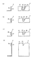
図4(a)〜(d)は、本発明に係るスリット開口の他の実施例を示す部分拡大した要部の正面図及び側面図である。 4 (a) to 4 (d) are a front view and a side view of a principal part partially enlarged showing another embodiment of the slit opening according to the present invention.
なお、図1〜図3と共通する部位には、共通の番号を付し、その説明は省略する。 In addition, the same number is attached | subjected to the site | part which is common in FIGS. 1-3, and the description is abbreviate | omitted.
図4(a)〜(c)は、スリット開口23の周縁には、内方に向けて突出された補強用リブ26を形成したものである。
4A to 4C, reinforcing
ずなわち、図4(a)では、スリット開口23の端縁よりも僅かに内方に、全周縁に亘って内側に向けて押出し形成された補強用リブ26を形成したものである。
In other words, in FIG. 4A, the reinforcing
また、図4(b)では、スリット開口23の端縁の一部を、内方に向けて折り曲げた鍔を形成することで、突出された補強用リブ26を形成したものである。
Further, in FIG. 4B, a protruding reinforcing
また、図4(c)では、スリット開口23の端縁の全周に亘って、内方に向けて折り曲げた鍔を形成することで、突出された補強用リブ26を形成したものである。
Further, in FIG. 4C, a protruding reinforcing
なお、図4(d)では、図4(a)〜(c)で示したスリット開口23の他の形状を示すものであり、スリット開口23の下端を、更に下方に向けて凹ませた溝23aを形成しており、このような溝23aを形成することで、受止折曲片11がスリット開口23に収納されたときには、受止折曲片11が溝23aに挟持されて係止できるのである。
4 (d) shows another shape of the slit opening 23 shown in FIGS. 4 (a) to 4 (c), and a groove in which the lower end of the slit opening 23 is recessed further downward. 23a is formed. By forming such a groove 23a, when the receiving
このような補強用リブ26を設けたものによれば、何れも内方に向けて突出された補強用リブ26を形成しているので、パネル受部材1を取付部材2に重合させて折畳み収納することができるうえ、スリット開口12の強度を高めて、搬送中における損傷を防止できる。
Since the reinforcing
更に、図4で示すように、スリット開口23の周端縁に、内側に向けて膨出された凸部27を形成することも可能である。
Furthermore, as shown in FIG. 4, it is possible to form a
具体的には、図4(a)では、スリット開口23の周端縁の適所に、内側に向けてヘソ状に膨出された1つの凸部27を形成したものである。
Specifically, in FIG. 4A, one
このような凸部27を設けたものによれば、図3で示すように、パネル受部材1を取付部材2に重合させて折畳み収納した後は、凸部27がパネル受部材1の受止折曲片11に圧接して保持するので、輸送中などの衝撃におけるガタツキを防止できる。
As shown in FIG. 3, after the panel receiving member 1 is overlapped with the mounting
また、凸部27は、その先端を半球状に形成しておけば、パネル受部材1をスリット開口23へスムーズに折畳んで収納できる。
Moreover, if the front-end | tip of the
また、図4(b)では、スリット開口23の周端縁の適所に、内側に向けてヘソ状に膨出された一対の凸部27を対向させて形成したものを示し、図4(c)では、スリット開口23の周端縁の適所に、内側に向けてヘソ状に膨出された一対の凸部27を段違いに対向させて形成したものを各々している。
FIG. 4B shows a structure in which a pair of
なお、これら図4(a)〜(c)で示されたスリット開口23の形状を、図4(d)のものに代えたものであっても、凸部27を形成できることは勿論である。
Of course, even if the shape of the slit opening 23 shown in FIGS. 4A to 4C is changed to that shown in FIG. 4D, the
図5は、本発明に係るスリット開口の更に他の実施例を示す屋根化粧パネル取付金具の起立状態の斜視図である。
なお、図1〜図4と共通する部位には、共通の番号を付し、その説明は省略する。
FIG. 5 is a perspective view in a standing state of a roof decorative panel mounting bracket showing still another embodiment of the slit opening according to the present invention.
In addition, the same number is attached | subjected to the site | part which is common in FIGS. 1-4, and the description is abbreviate | omitted.
このスリット開口23は、取付部材2の立上片21に間隔をあけて複数形成したことを特徴とする。
A plurality of the
このような複数のスリット開口23を形成すれば、パネル受部材1を折畳んだときに、このパネル受部材1の一片である受止折曲片11を、所望のスリット開口23の位置で、パネル受部材1を取付部材2に重合させて折畳み収納することを選択できる。
If such a plurality of
そのため、仮組み状態に折畳み収納された屋根化粧パネル取付金具Aの全長を選択することができ、例えば、輸送される梱包ケースの長さに応じて屋根化粧パネル取付金具Aの長さを調節し、輸送中などの衝撃におけるガタツキを防止できる。 Therefore, the total length of the roof decorative panel mounting bracket A folded and stored in a temporarily assembled state can be selected. For example, the length of the roof decorative panel mounting bracket A can be adjusted according to the length of the packaging case to be transported. This prevents rattling during impacts during transportation.
本発明は、屋根の軒先、ケラバ等に設けられる屋根化粧パネルを取付けるための屋根化粧パネル取付金具として有効に利用することが可能である。 INDUSTRIAL APPLICABILITY The present invention can be effectively used as a roof decorative panel mounting bracket for mounting a roof decorative panel provided on a roof eave, a keraba, or the like.
A 屋根化粧パネル取付金具
P 屋根化粧パネル
Y 屋根材
1 パネル受部材
11 一片(受止折曲片)
2 取付部材
23 スリット開口
3 連結具
A Roof decorative panel mounting bracket P Roof decorative panel Y Roof material 1
2 Mounting
Claims (6)
上記取付部材には、上記パネル受部材を折畳んだときに、このパネル受部材の一片を収容するスリット開口を形成したことを特徴とする屋根化粧パネル取付金具。 A panel receiving member for mounting the roof decorative panel and an attachment member attached to the roof material are rotatably connected by a connector, and the panel decorative member is configured such that the panel receiving member and the mounting member can be erected or folded. In the mounting bracket,
A roof decorative panel mounting bracket, wherein the mounting member is formed with a slit opening that accommodates a piece of the panel receiving member when the panel receiving member is folded.
上記スリット開口の周縁には、内方に向けて突出された補強用リブを形成したことを特徴とする屋根化粧パネル取付金具。 In claim 1,
A roof decorative panel mounting bracket, wherein reinforcing ribs projecting inward are formed on the periphery of the slit opening.
上記スリット開口の周端縁には、内側に向けて膨出された凸部を形成したことを特徴とする屋根化粧パネル取付金具。 In either claim 1 or 2,
A roof decorative panel mounting bracket, wherein a convex portion bulging inward is formed on a peripheral edge of the slit opening.
上記凸部の先端は、半球状に形成したことを特徴とする屋根化粧パネル取付金具。 In claim 3,
The roof decorative panel mounting bracket, wherein the tip of the convex part is formed in a hemispherical shape.
上記スリット開口は、開放側から閉止側に向けて、徐々に狭くなるテーパー状に形成したことを特徴とする屋根化粧パネル取付金具。 In any one of Claims 1-4,
The roof decorative panel mounting bracket, wherein the slit opening is formed in a tapered shape gradually narrowing from the open side to the closed side.
上記スリット開口は、間隔をあけて複数形成したことを特徴とする屋根化粧パネル取付金具。
In any one of Claims 1-5,
The roof decorative panel mounting bracket, wherein the slit opening is formed in plural at intervals.
Priority Applications (1)
| Application Number | Priority Date | Filing Date | Title |
|---|---|---|---|
| JP2004106731A JP3621701B1 (en) | 2004-03-31 | 2004-03-31 | Roof decorative panel mounting bracket |
Applications Claiming Priority (1)
| Application Number | Priority Date | Filing Date | Title |
|---|---|---|---|
| JP2004106731A JP3621701B1 (en) | 2004-03-31 | 2004-03-31 | Roof decorative panel mounting bracket |
Publications (2)
| Publication Number | Publication Date |
|---|---|
| JP3621701B1 JP3621701B1 (en) | 2005-02-16 |
| JP2005290816A true JP2005290816A (en) | 2005-10-20 |
Family
ID=34270139
Family Applications (1)
| Application Number | Title | Priority Date | Filing Date |
|---|---|---|---|
| JP2004106731A Expired - Fee Related JP3621701B1 (en) | 2004-03-31 | 2004-03-31 | Roof decorative panel mounting bracket |
Country Status (1)
| Country | Link |
|---|---|
| JP (1) | JP3621701B1 (en) |
Families Citing this family (1)
| Publication number | Priority date | Publication date | Assignee | Title |
|---|---|---|---|---|
| JP2006336215A (en) * | 2005-05-31 | 2006-12-14 | Takayama Metal Industrial Co Ltd | Nose cover mounting member |
-
2004
- 2004-03-31 JP JP2004106731A patent/JP3621701B1/en not_active Expired - Fee Related
Also Published As
| Publication number | Publication date |
|---|---|
| JP3621701B1 (en) | 2005-02-16 |
Similar Documents
| Publication | Publication Date | Title |
|---|---|---|
| JP6053728B2 (en) | Roof mount antenna mounting structure | |
| JP2004124583A (en) | Attaching fitting on roof | |
| US20020083660A1 (en) | Connector for manufactured home sidewall anchor strap | |
| JP3621701B1 (en) | Roof decorative panel mounting bracket | |
| JP5520579B2 (en) | Roof mounting fixture | |
| US7129410B2 (en) | Fuse box | |
| JP3624907B2 (en) | Roof decorative panel mounting bracket | |
| JP3871685B2 (en) | Roof decorative panel mounting bracket | |
| EP0069193B1 (en) | A collapsible membrane structure | |
| JP4740552B2 (en) | Antenna mast mounting bracket and antenna device | |
| JP2017186877A (en) | Mounting bracket and connecting structure of mounting bracket | |
| JP4716806B2 (en) | Electronic equipment case | |
| JPH1022714A (en) | Mast holder folding structure for antenna | |
| JP2006193059A (en) | Folding and fixing mechanism for handle bar | |
| JP5222868B2 (en) | Roof mounting fixture | |
| JP3576157B2 (en) | Roof panel mounting bracket | |
| JP5294485B2 (en) | Roof mounting fixture | |
| JP5448079B2 (en) | Roof mounting fixture and its mounting structure | |
| JP2004092290A (en) | Roof decoration panel fitting bracket | |
| EP3960544A1 (en) | Vehicle provided with a fairing under the fuel tank | |
| JP2023051488A (en) | Eaves gutter support and eaves gutter support structure | |
| JP2005325597A (en) | Fall prevention tool for temporary scaffolding | |
| JP3750943B2 (en) | Roof decorative panel mounting bracket | |
| JP4533916B2 (en) | Eaves structure | |
| JP6196845B2 (en) | Mounting base for folding plate roof installation |
Legal Events
| Date | Code | Title | Description |
|---|---|---|---|
| TRDD | Decision of grant or rejection written | ||
| A01 | Written decision to grant a patent or to grant a registration (utility model) |
Free format text: JAPANESE INTERMEDIATE CODE: A01 Effective date: 20041019 |
|
| A61 | First payment of annual fees (during grant procedure) |
Free format text: JAPANESE INTERMEDIATE CODE: A61 Effective date: 20041118 |
|
| R150 | Certificate of patent or registration of utility model |
Free format text: JAPANESE INTERMEDIATE CODE: R150 |
|
| FPAY | Renewal fee payment (event date is renewal date of database) |
Free format text: PAYMENT UNTIL: 20071126 Year of fee payment: 3 |
|
| FPAY | Renewal fee payment (event date is renewal date of database) |
Free format text: PAYMENT UNTIL: 20081126 Year of fee payment: 4 |
|
| FPAY | Renewal fee payment (event date is renewal date of database) |
Free format text: PAYMENT UNTIL: 20091126 Year of fee payment: 5 |
|
| FPAY | Renewal fee payment (event date is renewal date of database) |
Free format text: PAYMENT UNTIL: 20101126 Year of fee payment: 6 |
|
| FPAY | Renewal fee payment (event date is renewal date of database) |
Free format text: PAYMENT UNTIL: 20111126 Year of fee payment: 7 |
|
| FPAY | Renewal fee payment (event date is renewal date of database) |
Free format text: PAYMENT UNTIL: 20111126 Year of fee payment: 7 |
|
| FPAY | Renewal fee payment (event date is renewal date of database) |
Free format text: PAYMENT UNTIL: 20121126 Year of fee payment: 8 |
|
| FPAY | Renewal fee payment (event date is renewal date of database) |
Free format text: PAYMENT UNTIL: 20131126 Year of fee payment: 9 |
|
| R250 | Receipt of annual fees |
Free format text: JAPANESE INTERMEDIATE CODE: R250 |
|
| R250 | Receipt of annual fees |
Free format text: JAPANESE INTERMEDIATE CODE: R250 |
|
| LAPS | Cancellation because of no payment of annual fees |