JP2005290851A - Toilet bowl flushing water feeder - Google Patents
Toilet bowl flushing water feeder Download PDFInfo
- Publication number
- JP2005290851A JP2005290851A JP2004107668A JP2004107668A JP2005290851A JP 2005290851 A JP2005290851 A JP 2005290851A JP 2004107668 A JP2004107668 A JP 2004107668A JP 2004107668 A JP2004107668 A JP 2004107668A JP 2005290851 A JP2005290851 A JP 2005290851A
- Authority
- JP
- Japan
- Prior art keywords
- valve
- water channel
- pilot
- water
- water passage
- Prior art date
- Legal status (The legal status is an assumption and is not a legal conclusion. Google has not performed a legal analysis and makes no representation as to the accuracy of the status listed.)
- Pending
Links
- XLYOFNOQVPJJNP-UHFFFAOYSA-N water Substances O XLYOFNOQVPJJNP-UHFFFAOYSA-N 0.000 title claims abstract description 121
- 238000011010 flushing procedure Methods 0.000 title claims abstract description 32
- 238000005406 washing Methods 0.000 description 6
- 230000014759 maintenance of location Effects 0.000 description 5
- 230000007423 decrease Effects 0.000 description 3
- 238000001514 detection method Methods 0.000 description 3
- 238000004140 cleaning Methods 0.000 description 2
- 230000000694 effects Effects 0.000 description 2
- 238000010248 power generation Methods 0.000 description 2
- 238000004519 manufacturing process Methods 0.000 description 1
- 239000008400 supply water Substances 0.000 description 1
Images

Landscapes
- Sanitary Device For Flush Toilet (AREA)
Abstract
Description
本発明は、水道管から供給される水を便器に洗浄水として供給する便器洗浄水供給装置に関するものである。 The present invention relates to a toilet flushing water supply device that supplies water supplied from a water pipe to a toilet as washing water.
従来より、水道管と便器との間には、水道管から供給される水を便器に洗浄水として供給するための便器洗浄水供給装置が設けられている(特許文献1参照。)。 Conventionally, a toilet flushing water supply device is provided between a water pipe and a toilet bowl to supply water supplied from the water pipe to the toilet bowl as flush water (see Patent Document 1).
この便器洗浄水供給装置は、水道管に接続した一次側水路と便器に接続した二次側水路とを装置本体に形成し、これらの一次側水路と二次側水路との間にパイロット作動式の開閉弁を配設して、一次側水路と開閉弁の背圧室とを連通連結するとともに、背圧室と二次側水路とをパイロット水路で連通連結し、このパイロット水路にパイロット圧を変動させるための電磁弁及び手動弁を配設し、この電磁弁にコントローラを接続し、このコントローラに人体検出センサーを接続している。 This toilet flushing water supply device forms a primary side water channel connected to a water pipe and a secondary side water channel connected to a toilet in the main body of a device, and is a pilot-operated type between the primary side water channel and the secondary side water channel. An on-off valve is provided to connect the primary water channel and the back pressure chamber of the on-off valve in communication, and the back pressure chamber and secondary side water channel are connected to each other through a pilot water channel, and pilot pressure is applied to the pilot water channel. An electromagnetic valve and a manual valve for changing are provided, a controller is connected to the electromagnetic valve, and a human body detection sensor is connected to the controller.
そして、便器洗浄水供給装置は、次のようにして水道管から供給された水を便器へ供給するようにしている。 And the toilet bowl washing | cleaning water supply apparatus supplies the water supplied from the water pipe to the toilet bowl as follows.
まず、電磁弁及び手動弁が閉塞された状態では、水道管から一次側水路を介して供給された水によって開閉弁の背圧室に水圧がかかる一方、二次側水路は大気に開放されているため、背圧室の方が二次側水路よりも圧力が高くなり、この圧力差の作用で開閉弁が閉塞されている。 First, when the solenoid valve and the manual valve are closed, the water supplied from the water pipe through the primary side water passage applies water pressure to the back pressure chamber of the on-off valve, while the secondary side water passage is opened to the atmosphere. Therefore, the pressure in the back pressure chamber is higher than that in the secondary water channel, and the on-off valve is closed by the effect of this pressure difference.
次に、人体検出センサーによって使用者が便器から離座したことを検出すると、コントローラが電磁弁を開放するように制御し、これによって、パイロット水路を介して背圧室から二次側水路に水が流れ込み、背圧室と二次側水路との圧力差が減少し、それに伴って、開閉弁が開放され、水圧によって一次側水路から二次側水路へと水が一気に流れ込み、二次側水路から便器に水が供給される。 Next, when it is detected by the human body detection sensor that the user has left the toilet, the controller controls the solenoid valve to be opened, thereby allowing water from the back pressure chamber to the secondary side water channel via the pilot water channel. The pressure difference between the back pressure chamber and the secondary side water channel decreases, and the open / close valve is opened accordingly, and water flows from the primary side water channel to the secondary side water channel due to the water pressure. Water is supplied to the toilet.
また、上記便器洗浄水供給装置では、停電や故障などによって電磁弁が自動的に開放されなかった場合には、手動弁を操作することによっても水を供給することができるようになっている。 Further, in the toilet flushing water supply device, when the electromagnetic valve is not automatically opened due to a power failure or failure, water can be supplied also by operating the manual valve.
この場合も、上記同様、手動弁の開放操作によってパイロット水路を介して背圧室から二次側水路に水が流れ込み、一次側水路と二次側水路との圧力差が減少し、それに伴って、開閉弁が開放され、水圧によって一次側水路から二次側水路へと水が一気に流れ込み、二次側水路から便器に水が供給される。 In this case as well, as described above, water flows from the back pressure chamber into the secondary water channel through the pilot water channel by opening the manual valve, and the pressure difference between the primary water channel and the secondary water channel decreases accordingly. The on-off valve is opened, and water flows from the primary side waterway to the secondary side waterway at a stretch by water pressure, and water is supplied from the secondary side waterway to the toilet.
この従来の便器洗浄水供給装置では、手動弁を止水時に一次側水路と同圧となるパイロット水路内で弁体が開閉動作するように配設されており、しかも、装置本体の外部に取付けた連通管でパイロット水路を形成していた。 In this conventional toilet flushing water supply device, the manual valve is arranged so that the valve element opens and closes in the pilot water channel that is at the same pressure as the primary side water channel when water is stopped, and is attached to the outside of the device main body. A pilot waterway was formed by the communication pipe.
また、従来の便器洗浄水供給装置では、パイロット水路の上部側に手動弁を配置し、パイロット水路の下部側に電磁弁を配置していた。
ところが、従来の便器洗浄水供給装置にあっては、手動弁をパイロット水路の一次側水路側で弁体が開閉動作するように配設されていたために、手動弁を開放操作する際には、一次側水路にかかる水圧に抗して手動弁を操作しなければならず、操作力が大きくなって操作性が悪くなるおそれがあった。 However, in the conventional toilet flushing water supply device, since the manual valve is disposed so that the valve body opens and closes on the primary water channel side of the pilot water channel, when opening the manual valve, The manual valve had to be operated against the water pressure applied to the primary water channel, and there was a possibility that the operability would be increased and the operability would be deteriorated.
また、従来の便器洗浄水供給装置にあっては、パイロット水路を構成する連通管を装置本体の外部に取付けていたため、小型化が困難であり、部品点数の増加に伴って組立作業性が低減し製造コストが増大するおそれがあった。 In addition, in the conventional toilet flushing water supply device, since the communication pipe constituting the pilot water channel is attached to the outside of the device main body, it is difficult to reduce the size, and the assembly workability decreases as the number of parts increases. However, the manufacturing cost may increase.
さらに、従来の便器洗浄水供給装置にあっては、パイロット水路の下部側に頻繁に使用される電磁弁を配設していたために、電磁弁の開閉時に生じる気泡を円滑に外部に排出することができず、電磁弁の開閉動作が円滑に行えなくなるおそれがあった。 Furthermore, in the conventional toilet flushing water supply device, since the frequently used electromagnetic valve is disposed on the lower side of the pilot water channel, bubbles generated when the electromagnetic valve is opened and closed can be smoothly discharged to the outside. There was a risk that the solenoid valve could not be smoothly opened and closed.
そこで、請求項1に係る本発明では、給水源に接続した一次側水路と便器に接続した二次側水路とを装置本体に形成し、これらの一次側水路と二次側水路との間にパイロット作動式の開閉弁を配設して、一次側水路と開閉弁の背圧室とを連通連結するとともに、背圧室と二次側水路とをパイロット水路で連通連結し、このパイロット水路にパイロット圧を変動させるための電磁弁及び手動弁を配設した便器洗浄水供給装置において、前記手動弁は、前記パイロット水路と二次側水路とを連通する連通孔の二次側水路側に弁体を開閉可能に配設することにした。 Therefore, in the present invention according to claim 1, a primary side water channel connected to the water supply source and a secondary side water channel connected to the toilet are formed in the apparatus main body, and between these primary side water channel and secondary side water channel. A pilot-actuated on-off valve is provided to connect the primary side water passage and the back pressure chamber of the on-off valve in communication, and the back pressure chamber and secondary side water passage are connected to each other through the pilot water passage. In the toilet flushing water supply apparatus provided with a solenoid valve and a manual valve for changing the pilot pressure, the manual valve is a valve on the secondary side water channel side of the communication hole communicating the pilot water channel and the secondary side water channel. The body was arranged to be openable and closable.
また、請求項2に係る本発明では、前記請求項1に係る本発明において、前記パイロット水路を前記装置本体の内部に一体的に形成することにした。
Also, in the present invention according to
また、請求項3に係る本発明では、前記請求項1又は請求項2のいずれかに係る本発明において、前記パイロット水路の前記一次水路側に電磁弁、その下流側に手動弁を配置することにした。
Moreover, in this invention which concerns on Claim 3, in this invention which concerns on either said Claim 1 or
また、請求項4に係る本発明では、前記請求項3に係る本発明において、前記電磁弁は、鉛直方向に駆動するアクチュエータを具備することにした。
In the present invention according to
そして、本発明では、以下に記載する効果を奏する。 And in this invention, there exists an effect described below.
すなわち、請求項1に係る本発明では、給水源に接続した一次側水路と便器に接続した二次側水路とを装置本体に形成し、これらの一次側水路と二次側水路との間にパイロット作動式の開閉弁を配設して、一次側水路と開閉弁の背圧室とを連通連結するとともに、背圧室と二次側水路とをパイロット水路で連通連結し、このパイロット水路にパイロット圧を変動させるための電磁弁及び手動弁を配設した便器洗浄水供給装置において、前記手動弁は、前記パイロット水路と二次側水路とを連通する連通孔の二次側水路側に弁体を開閉可能に配設しているために、大気に開放された二次側水路の圧力に抗して手動弁を開放操作すればよくなり、手動弁の開放操作に要する操作力を低減させることができ、手動弁の操作性を向上させることができる。 That is, in this invention which concerns on Claim 1, the primary side water channel connected to the water supply source and the secondary side water channel connected to the toilet bowl are formed in an apparatus main body, and between these primary side water channels and secondary side water channels. A pilot-actuated on-off valve is provided to connect the primary side water passage and the back pressure chamber of the on-off valve in communication, and the back pressure chamber and secondary side water passage are connected to each other through the pilot water passage. In the toilet flushing water supply apparatus provided with a solenoid valve and a manual valve for changing the pilot pressure, the manual valve is a valve on the secondary side water channel side of the communication hole communicating the pilot water channel and the secondary side water channel. Since the body is arranged to be openable and closable, it is only necessary to open the manual valve against the pressure of the secondary water channel that is open to the atmosphere, reducing the operating force required to open the manual valve. Can improve the operability of the manual valve .
また、請求項2に係る本発明では、パイロット水路を装置本体の内部に一体的に形成しているために、装置本体の外部に連通管を接続する必要がなくなり、便器洗浄水供給装置の小型化を図ることができるとともに、部品点数の減少により組立作業性の向上や便器洗浄水供給装置の低廉化を図ることができる。
Further, in the present invention according to
また、請求項3に係る本発明では、パイロット水路の一次水路側に電磁弁、その下流側に手動弁を配置しているために、頻繁に開閉される電磁弁によって一次側水路から流入した気泡を円滑に外部に排出することができる。 Further, in the present invention according to claim 3, since the solenoid valve is disposed on the primary water channel side of the pilot water channel and the manual valve is disposed on the downstream side thereof, air bubbles that have flowed in from the primary water channel by the electromagnetic valve that is frequently opened and closed Can be smoothly discharged to the outside.
また、請求項4に係る本発明では、電磁弁のアクチュエータを鉛直方向に駆動するようにしているために、電磁弁に一次側水路から流入した気泡をより一層円滑に外部に排出することができる。
Further, in the present invention according to
以下に、本発明に係る便器洗浄水供給装置の具体的な構造について図面を参照しながら説明する。 Below, the concrete structure of the toilet bowl washing water supply apparatus which concerns on this invention is demonstrated, referring drawings.
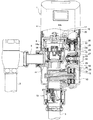
便器洗浄水供給装置1は、図1に示すように、給水源としての水道管に接続された給水管2と便器に接続された洗浄水供給管3との間に介設され、水道管から供給された水を便器に洗浄水として供給するようにしている。
As shown in FIG. 1, the toilet flushing water supply device 1 is interposed between a
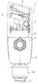
この便器洗浄水供給装置1は、図1及び図2に示すように、中空状のケーシング4の内側上部に人体検出センサー5と制御装置6と電池7とを配設するとともに、ケーシング4の内側下部に装置本体8を配設している。
As shown in FIGS. 1 and 2, the toilet flushing water supply device 1 is provided with a human body detection sensor 5, a
装置本体8は、左側上部に給水管2と接続する入水管9を接続するとともに、下部に洗浄水供給管3をバキュームブレーカ10を介して接続している。
The apparatus
また、装置本体8は、内側上部に給水管2を介して水道管と連通する一次側水路11を形成する一方、内側下部に洗浄水供給管3を介して便器と連通する二次側水路12を形成しており、この二次側水路12の中途部には水流を利用して発電を行う発電ユニット13を配設し、この発電ユニット13を制御装置6に接続している。
Moreover, the apparatus
そして、装置本体8は、一次側水路11と二次側水路12との間にパイロット作動式の開閉弁14を上下方向に向けて開閉可能に配設し、この開閉弁14の上方に背圧室14aを形成し、この背圧室14aと一次側水路11とを開閉弁14に形成したブリード孔14bを介して連通連結する一方、背圧室14aと二次側水路12とを開閉弁14に隣接させて形成したパイロット水路15で連通連結している。
The
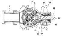
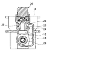
このパイロット水路15は、図1、図3及び図4に示すように、開閉弁14の上部に形成された背圧室14aに一次側パイロット水路16を連通孔17を介して連通連結し、この一次側パイロット水路16に装置本体8の前側に一体的に形成した連通パイロット水路18を連通連結している。
As shown in FIGS. 1, 3 and 4, the
そして、パイロット水路15は、一次側パイロット水路16と二次側水路12との間に制御装置6で開閉制御されることでパイロット圧を変動させる電磁弁20を介設するとともに、連通パイロット水路18と二次側水路12との間に手動操作されることでパイロット圧を変動させる手動弁21を介設している。
The
すなわち、便器洗浄水供給装置1は、装置本体8の上部に形成した一次側パイロット水路16と装置本体8の右側前部に形成した連通パイロット水路18とでパイロット水路15を構成するとともに、装置本体8の内部であって、かつ開閉弁14と隣接させた位置にパイロット水路15を装置本体8と一体的に形成し、このパイロット水路15の上部側の一次側パイロット水路16に電磁弁20を配設し、パイロット水路15の下部側の連通パイロット水路18に手動弁21を配設している。
That is, the toilet flushing water supply device 1 includes a
この電磁弁20は、装置本体8の右側上部に形成した開口部22に中心軸を上下方向に向けた状態で挿入して取付けられており、装置本体8の一次側パイロット水路16の右端部と二次側水路12の上端部との間に連通孔23を形成し、この連通孔23の周囲に環状の弁座24を形成し、この弁座24に弁体25を接離自在に配設し、この弁体25に上下方向へ向けて進退移動するアクチュエータ26を連動連結している。
The
一方、手動弁21は、装置本体8の右側部に形成した開口部27に中心軸を左右方向に向けた状態で挿入して取付けられており、装置本体8の連通パイロット水路18の下端部と二次側水路12の中途部との間に連通孔28を形成し、この連通孔28に円筒状のホルダー29を挿通し、このホルダー29の先端部に環状の弁座30を形成し、この弁座30の先端側に円板上の弁体31を接離自在に配設し、この弁体31に略円柱状の操作スイッチ32の先端に取付けている。
On the other hand, the
また、手動弁21は、操作スイッチ32の先端側に小径筒部33を形成するとともに、この小径筒部33の周囲に滞留室34を形成し、一方、ホルダー29に連通パイロット水路18と滞留室34とを連通させる連通孔35を形成しており、さらに、操作スイッチ32の中途部とホルダー29の先端部との間に操作スイッチ32を介して弁体31を弁座30に付勢するバネ36を介設している。
Further, the
したがって、手動弁21は、パイロット水路15と二次側水路12とを連通する連通孔28の二次側水路側に弁体31を開閉可能に配設している。
Therefore, the
そして、手動弁21は、図5(a)に示すように、通常時には、弁体31が弁座30に当接して閉塞状態となっており、この閉塞状態では、給水管2から流れ込んだ水が背圧室14aから一次側パイロット水路16と連通パイロット水路18とを介して滞留室34に流れ込む。この閉塞状態では、弁体31が弁座30と当接するシート径とOリング37のホルダー29に対する摺動径とがほぼ同一であるため、滞留室34に流れ込んだ水圧(背圧室14aの水圧)が図5(a)において左右方向に及ぼすお互いの圧力が相殺しあっている。
As shown in FIG. 5 (a), the
この閉塞状態から操作スイッチ32が押圧操作されると、図5(b)に示すように、弁体31が弁座30から離反して二次側水路12の方向へ移動し、滞留室34と二次側水路12とが連通されて、手動弁21が開放状態となる。
When the
この開放状態では、給水管2から流れ込んだ水が背圧室14aから一次側パイロット水路16と連通パイロット水路18とを介して滞留室34に流れ、さらに、滞留室34から二次側水路12へと流れ込む。
In this open state, water flowing from the
その際には、弁体31の移動方向側である二次側水路12が大気開放状態となっているために、弁体31の移動を阻止するような圧力が弁体31の移動方向側にかかっておらず、バネ36の付勢力に抗して操作スイッチ32を押圧操作するだけで、手動弁21を開放状態とすることができる。
At that time, since the secondary
そして、手動弁21が開放状態となると、背圧室14aから二次側水路12に向けて少しずつ水が流れ、これによって、背圧室14aと二次側水路12との圧力差が減少し、背圧室14aの水圧で付勢されていた開閉弁14が開放され、一次側水路11から二次側水路12に向けて一気に水が流れ出る。
When the
以上に説明したように、便器洗浄水供給装置1は、水道管に接続した一次側水路11と便器に接続した二次側水路12とを装置本体8に形成し、これらの一次側水路11と二次側水路12との間にパイロット作動式の開閉弁14を配設して、一次側水路11と開閉弁14の背圧室14aとを連通連結するとともに、背圧室14aと二次側水路12とをパイロット水路15で連通連結し、このパイロット水路15にパイロット圧を変動させるための電磁弁20及び手動弁21を配設している。
As described above, the toilet flushing water supply device 1 forms the primary
そして、便器洗浄水供給装置1は、パイロット水路15と二次側水路12とを連通する連通孔28の二次側水路側に手動弁21の弁体31を開閉可能に配設している。
In the toilet flushing water supply device 1, the
そのため、便器洗浄水供給装置1は、大気に開放された二次側水路12の圧力(大気圧)に抗して手動弁21を開放操作すればよくなり、手動弁21の開放操作に要する操作力を低減させることができ、手動弁21の操作性を向上させることができる。
Therefore, the toilet flushing water supply device 1 has only to open the
しかも、便器洗浄水供給装置1は、パイロット水路15を装置本体8の内部に一体的に形成しているために、装置本体8の外部に別途連通管を接続する必要がなくなり、便器洗浄水供給装置1の小型化を図ることができるとともに、部品点数の減少により組立作業性の向上や便器洗浄水供給装置1の低廉化を図ることができる。
In addition, since the toilet flushing water supply device 1 integrally forms the
また、便器洗浄水供給装置1は、パイロット水路15を開閉弁14に隣接させて形成しているために、便器洗浄水供給装置1の小型化を図ることができる。
Further, since the toilet flushing water supply device 1 is formed with the
さらに、便器洗浄水供給装置1は、パイロット水路15の一次水路側に電磁弁20、その下流側に手動弁21を配置しているために、頻繁に開閉される電磁弁20に一次側水路11から流入した気泡を円滑に外部に排出することができる。特に、電磁弁20のアクチュエータ26を鉛直方向に駆動するようにしているために、電磁弁20に一次側水路11から流入した気泡をより一層円滑に外部に排出することができる。
Further, since the toilet flushing water supply device 1 is provided with the
なお、本実施例では、左側から給水が行われる便器洗浄水供給装置1について説明したが、右側から給水が行われるものにも本発明を適用できる。 In addition, in the present Example, although the toilet bowl wash water supply apparatus 1 supplied with water from the left side was demonstrated, this invention is applicable also to what is supplied with water from the right side.
1 便器洗浄水供給装置
2 給水管
3 洗浄水供給管
4 ケーシング
8 装置本体
9 入水管
11 一次側水路
12 二次側水路
14 開閉弁
14a 背圧室
15 パイロット水路
16 一次側パイロット水路
18 連通パイロット水路
20 電磁弁
21 手動弁
29 ホルダー
30 弁座
31 弁体
32 操作スイッチ
34 滞留室
35 連通孔
36 バネ
37 Oリング
DESCRIPTION OF SYMBOLS 1 Toilet wash
11 Primary waterway
12 Secondary waterway
14 On-off valve
14a Back pressure chamber
15 pilot waterway
16 Primary pilot canal
18 Communication pilot waterway
20 Solenoid valve
21 Manual valve
29 Holder
30 Valve seat
31 Disc
32 Operation switch
34 Residence room
35 communication hole
36 Spring
37 O-ring
Claims (4)
前記手動弁は、前記パイロット水路と二次側水路とを連通する連通孔の二次側水路側に弁体を開閉可能に配設したことを特徴とする便器洗浄水供給装置。 A primary side water channel connected to the water supply source and a secondary side water channel connected to the toilet are formed in the apparatus body, and a pilot-operated on-off valve is disposed between the primary side water channel and the secondary side water channel. In addition, the primary side water passage and the back pressure chamber of the on-off valve are connected in communication with each other, and the back pressure chamber and the secondary side water passage are connected in communication with each other through a pilot water passage. In the toilet flushing water supply device provided with a valve,
The toilet flushing water supply device according to claim 1, wherein the manual valve is disposed such that a valve body can be opened and closed on a secondary side water channel side of a communication hole communicating the pilot water channel and the secondary side water channel.
Priority Applications (1)
| Application Number | Priority Date | Filing Date | Title |
|---|---|---|---|
| JP2004107668A JP2005290851A (en) | 2004-03-31 | 2004-03-31 | Toilet bowl flushing water feeder |
Applications Claiming Priority (1)
| Application Number | Priority Date | Filing Date | Title |
|---|---|---|---|
| JP2004107668A JP2005290851A (en) | 2004-03-31 | 2004-03-31 | Toilet bowl flushing water feeder |
Publications (1)
| Publication Number | Publication Date |
|---|---|
| JP2005290851A true JP2005290851A (en) | 2005-10-20 |
Family
ID=35324097
Family Applications (1)
| Application Number | Title | Priority Date | Filing Date |
|---|---|---|---|
| JP2004107668A Pending JP2005290851A (en) | 2004-03-31 | 2004-03-31 | Toilet bowl flushing water feeder |
Country Status (1)
| Country | Link |
|---|---|
| JP (1) | JP2005290851A (en) |
Cited By (1)
| Publication number | Priority date | Publication date | Assignee | Title |
|---|---|---|---|---|
| JP2021127645A (en) * | 2020-02-17 | 2021-09-02 | Toto株式会社 | Valve unit and water closet equipped with the same |
-
2004
- 2004-03-31 JP JP2004107668A patent/JP2005290851A/en active Pending
Cited By (2)
| Publication number | Priority date | Publication date | Assignee | Title |
|---|---|---|---|---|
| JP2021127645A (en) * | 2020-02-17 | 2021-09-02 | Toto株式会社 | Valve unit and water closet equipped with the same |
| JP7382008B2 (en) | 2020-02-17 | 2023-11-16 | Toto株式会社 | Valve unit and flush toilet equipped with it |
Similar Documents
| Publication | Publication Date | Title |
|---|---|---|
| KR100705193B1 (en) | Water closet | |
| CN101046105B (en) | Vacuum sewer system | |
| KR950006325B1 (en) | Toilet water supply | |
| US6254057B1 (en) | Valve control system | |
| CN100572703C (en) | Vacuum Sewage System | |
| WO2011063406A1 (en) | Electronic flush valve with optional manual override | |
| MXPA04005485A (en) | Automatic bathroom flushers. | |
| WO2007050299A3 (en) | Automatic flush actuation apparatus | |
| JP2005290851A (en) | Toilet bowl flushing water feeder | |
| JP6627339B2 (en) | Hot water supply system and drainage device | |
| JP4745888B2 (en) | Self-closing faucet | |
| EP1343064A8 (en) | Pressure control valve | |
| JP2007138984A (en) | Float type steam trap | |
| JP6497499B2 (en) | Hot and cold water mixing device | |
| JP2008031784A (en) | Water pressure control device and flushing valve unit for flush toilet bowl | |
| JP2018119328A (en) | Toilet bowl flushing device and toilet bowl device including the same | |
| JP2021055419A (en) | Flush toilet bowl | |
| JP4767875B2 (en) | Pilot type on-off valve | |
| JP2007333193A (en) | Water supply device | |
| JP7415302B2 (en) | flush toilet | |
| JP7441675B2 (en) | Open/close valve device | |
| JP6560145B2 (en) | Valve device and toilet bowl cleaning device | |
| JP3786246B2 (en) | On-off valve | |
| JP4494938B2 (en) | Pressure reducing valve | |
| KR20070017211A (en) | Tankless Flush Toilet |
Legal Events
| Date | Code | Title | Description |
|---|---|---|---|
| A621 | Written request for application examination |
Free format text: JAPANESE INTERMEDIATE CODE: A621 Effective date: 20061106 |
|
| A977 | Report on retrieval |
Free format text: JAPANESE INTERMEDIATE CODE: A971007 Effective date: 20070828 |
|
| A131 | Notification of reasons for refusal |
Free format text: JAPANESE INTERMEDIATE CODE: A131 Effective date: 20081202 |
|
| A521 | Written amendment |
Free format text: JAPANESE INTERMEDIATE CODE: A523 Effective date: 20090129 |
|
| A02 | Decision of refusal |
Effective date: 20090303 Free format text: JAPANESE INTERMEDIATE CODE: A02 |