JP2005290966A - Sheet shutter - Google Patents
Sheet shutter Download PDFInfo
- Publication number
- JP2005290966A JP2005290966A JP2004218519A JP2004218519A JP2005290966A JP 2005290966 A JP2005290966 A JP 2005290966A JP 2004218519 A JP2004218519 A JP 2004218519A JP 2004218519 A JP2004218519 A JP 2004218519A JP 2005290966 A JP2005290966 A JP 2005290966A
- Authority
- JP
- Japan
- Prior art keywords
- sheet
- plate
- shutter
- pressing member
- seat
- Prior art date
- Legal status (The legal status is an assumption and is not a legal conclusion. Google has not performed a legal analysis and makes no representation as to the accuracy of the status listed.)
- Pending
Links
- 230000007246 mechanism Effects 0.000 claims abstract description 23
- 229920005989 resin Polymers 0.000 claims description 26
- 239000011347 resin Substances 0.000 claims description 26
- 238000000926 separation method Methods 0.000 claims description 24
- 230000003014 reinforcing effect Effects 0.000 claims description 5
- 239000002783 friction material Substances 0.000 claims description 4
- 238000004804 winding Methods 0.000 claims description 3
- 230000035699 permeability Effects 0.000 abstract description 2
- 238000010586 diagram Methods 0.000 description 10
- 230000009471 action Effects 0.000 description 5
- 238000005452 bending Methods 0.000 description 2
- 239000000428 dust Substances 0.000 description 2
- 230000004048 modification Effects 0.000 description 2
- 238000012986 modification Methods 0.000 description 2
- 239000004698 Polyethylene Substances 0.000 description 1
- 229910000831 Steel Inorganic materials 0.000 description 1
- 230000008859 change Effects 0.000 description 1
- 239000003638 chemical reducing agent Substances 0.000 description 1
- 230000004927 fusion Effects 0.000 description 1
- 230000005484 gravity Effects 0.000 description 1
- 238000000034 method Methods 0.000 description 1
- 229920000728 polyester Polymers 0.000 description 1
- -1 polyethylene Polymers 0.000 description 1
- 229920000573 polyethylene Polymers 0.000 description 1
- 229920000915 polyvinyl chloride Polymers 0.000 description 1
- 239000004800 polyvinyl chloride Substances 0.000 description 1
- 230000002787 reinforcement Effects 0.000 description 1
- 239000010959 steel Substances 0.000 description 1
- 229920003002 synthetic resin Polymers 0.000 description 1
- 239000000057 synthetic resin Substances 0.000 description 1
- 238000003466 welding Methods 0.000 description 1
Images



Landscapes
- Operating, Guiding And Securing Of Roll- Type Closing Members (AREA)
Abstract
Description
本発明は、建物の出入り口を開閉するシートシャッターに関する。特には、シートの幅方向の変形を抑制するための補強パイプのないフラットタイプのシートシャッターに関する。 The present invention relates to a sheet shutter that opens and closes a doorway of a building. In particular, the present invention relates to a flat type sheet shutter having no reinforcing pipe for suppressing deformation in the width direction of the sheet.
シートシャッターには、シートの幅方向に延びるパイプを、シートの上下方向中間部分に所定の間隔毎に固定したタイプのものがある。シートに固定されたパイプは、シートに耐風圧力を与える補強部材として用いられており、シャッターが閉じられたときにおける、シートの表裏面にかかる圧力の差によるシートの変形を防いでいる。この補強パイプがないと、風を受けた帆のように、シートが低圧方向に押し込まれる。このような補強パイプは、通常、シート片に巻き込まれた後に、該シート片をシートの全幅方向に渡って溶着して固定されている。 There is a type of sheet shutter in which pipes extending in the width direction of a sheet are fixed at a predetermined interval at an intermediate portion in the vertical direction of the sheet. The pipe fixed to the sheet is used as a reinforcing member that gives wind resistance pressure to the sheet, and prevents deformation of the sheet due to a difference in pressure applied to the front and back surfaces of the sheet when the shutter is closed. Without this reinforcement pipe, the seat is pushed in the low pressure direction like a sail that has received wind. Such a reinforcing pipe is usually fixed by being wound around the sheet piece and then welding the sheet piece over the entire width direction of the sheet.
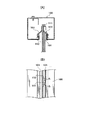
図5は、パイプ付きのシートを用いたシャッターが閉じられたときにおける、シート案内部の状態を説明する図であり、図5(A)はレールボックスの横断面図、図5(B)はレールボックスの側面図である。
図5(A)に示すように、レールボックス100には、上下方向に延びるレール案内開口101が形成されている。シャッターの上げ下げ時にシート110の幅方向端部はこのレール案内開口101を上下する。レール案内開口101の両側には、樹脂ガイド103が設けられている。シャッターを閉じたとき、シート110の幅方向端部の表裏面には、樹脂ガイド103が当っている。これにより、レール案内開口101とレールボックス100内部の間を極力塞いで、空気がシート110の一方の側(例えば表側)の空間から、レールボックス100内を通ってシート110の他方(例えば裏側)の空間へ流れることを防ごうとしている。
5A and 5B are diagrams for explaining the state of the sheet guide portion when the shutter using the pipe-attached sheet is closed. FIG. 5A is a cross-sectional view of the rail box, and FIG. It is a side view of a rail box.
As shown in FIG. 5A, the
しかし、このようなパイプ付きのシートにおいては、シャッターを閉じたときに、以下のような問題点が生じる。つまり、シート110にパイプ111が固定されている部分では、図5(B)に示すように、樹脂ガイド103がパイプ111に当ってシート110に密着せず、シート110と樹脂ガイド103の間にスキマSができ、埃や塵が室内に入り込む原因となる。
However, such a sheet with a pipe has the following problems when the shutter is closed. That is, in the portion where the
一方、パイプが設けられていないフラットシートを用いたパイプレスシートシャッターもある。この種のシャッターは、パイプがないため、シャッターが閉じられたときにシートの表裏面に樹脂ガイドが完全に密着し、気密性が向上する。また、このようなシートシャッターは、パイプがないため見栄えがよいという特長を有する。さらに、シートの重量が軽くなるため、モータにかかる負荷も少なくなる。 On the other hand, there is also a pipeless seat shutter using a flat sheet without a pipe. Since this type of shutter has no pipe, the resin guide is completely adhered to the front and back surfaces of the sheet when the shutter is closed, and the airtightness is improved. Further, such a sheet shutter has a feature that it looks good because there is no pipe. Furthermore, since the weight of the seat is reduced, the load on the motor is also reduced.
しかし、フラットシートはパイプがないため耐風圧性が弱く、シートの表裏面にかかる圧力の差によってはシートが帆のように大きくふくらんで、ひどい場合にはレールボックスからシートの端が抜けてしまう事態ともなりうる。このため、フラットシートシャッターは、シートの表裏面での圧力の差が比較的小さい室内向けや、比較的幅が狭いシャッターにしか用いられていない。そして、シャッター開口に広い幅が必要であったり、シートの表裏面の圧力差が大きい場合(室内を含む)は、パイプ付きのシートシャッターを用いざるを得ない。 However, the flat sheet has a low wind resistance because there is no pipe, and depending on the pressure difference between the front and back surfaces of the sheet, the sheet swells like a sail, and in extreme cases, the end of the sheet comes out of the rail box. Can also be. For this reason, the flat sheet shutter is used only for a room where the difference in pressure between the front and back surfaces of the sheet is relatively small, and a shutter having a relatively narrow width. When a wide opening is required for the shutter opening or when the pressure difference between the front and back surfaces of the sheet is large (including the room), a sheet shutter with a pipe must be used.
本発明は上記の問題点に鑑みてなされたものであって、シートとレールボックスとの気密性を向上させるとともに、フラットシートにおいてもシートの張りを保つことのできるシートシャッターを提供することを目的とする。 The present invention has been made in view of the above problems, and it is an object of the present invention to provide a sheet shutter capable of improving the airtightness between the seat and the rail box and maintaining the tension of the sheet even in a flat sheet. And
本発明のシートシャッターは、 建物の開口において上げ下げされ該開口を開閉するシートと、該シートを巻き上げ・巻き下げる手段と、前記シートの幅方向両端部を上下に案内するレールボックスと、を備えるシートシャッターであって、 前記シートは、上下方向中間部分に、シートの幅方向の変形を抑制するための補強部材のないフラットなものであり、 前記レールボックスが、 上下方向に延びる、前記シートの幅方向の端部の挿通されるスリット状の案内部を有するボックス本体と、 該ボックス本体内において上下方向に延びるように設けられた、前記シートが閉限にある場合に前記シートに対して押し当てられる押し当て部材と、を具備することを特徴とする。 A seat shutter according to the present invention comprises: a seat that is raised and lowered at an opening of a building to open and close the opening; means for winding and lowering the seat; and a rail box that guides both ends in the width direction of the seat up and down. The sheet is a flat sheet without a reinforcing member for suppressing deformation in the width direction of the sheet at an intermediate portion in the vertical direction, and the rail box extends in the vertical direction. A box main body having a slit-shaped guide portion inserted through an end of the direction, and provided in the box main body so as to extend in the vertical direction and pressed against the sheet when the sheet is in a closed limit And a pressing member to be provided.
シートの幅方向端部を押し当て部材で押してボックス本体に対して固定するとともに、シート案内部とシートとのスキマを減らすことができる。そのため、シートの表裏面で気圧の差が高い場合でも、シートが撓んだり、レールボックスから抜け出ることを防止できる。また、シートシャッターの気密性を高めることができる。 While pressing the width direction edge part of a sheet | seat with a pressing member and fixing with respect to a box main body, the clearance gap between a sheet | seat guide part and a sheet | seat can be reduced. Therefore, even when the pressure difference between the front and back surfaces of the seat is high, the seat can be prevented from being bent or coming out of the rail box. Further, the airtightness of the sheet shutter can be improved.
本発明においては、 前記押し当て部材を前記シートに押し当てる機構が、 該押し当て部材に接続された、前記シートによって下に押されるアームと、 該アームの下降に伴って回動する、前記押し当て部材に回動可能に連結されたリンクと、を有することが好ましい。 In the present invention, the mechanism that presses the pressing member against the sheet includes an arm that is connected to the pressing member and is pressed downward by the sheet, and that rotates as the arm is lowered. It is preferable to have a link rotatably connected to the abutting member.
シャッターが閉じられたときに、自動的に押し当て部材をシート方向に移動させて、シートを挟み込むことができる。また、シャッターが開かれると、自動的に案内部の開口を開くことができる。つまり、シート押し当て部材用の別のアクチュエータを必要とない。 When the shutter is closed, the pressing member can be automatically moved in the sheet direction to sandwich the sheet. Further, when the shutter is opened, the opening of the guide portion can be automatically opened. That is, another actuator for the sheet pressing member is not required.
本発明においては、 前記押し当て部材が、前記シート端部に当てられて同部を挟持するように相対駆動される表当て板及び裏当て板を含み、 両板の前記シート端部を挟持する面に、互いに係合し合う凹凸を形成することもできる。
凹面と凸面でシート端部を挟持することにより、同部をしっかりと挟み込むことができる。これにより、シート端部の本体ボックスからの抜けを防止できるとともに、シートの前側と後側との気密性が得られる。
In the present invention, the pressing member includes a front abutting plate and a backing plate that are relatively driven so as to be applied to the end portion of the sheet and sandwich the portion, and sandwich the sheet end portion of both plates. Irregularities that engage with each other can also be formed on the surface.
By sandwiching the sheet end portion between the concave surface and the convex surface, the same portion can be firmly sandwiched. Thereby, while being able to prevent the sheet | seat edge part from slipping out from the main body box, the airtightness of the front side and rear side of a sheet | seat is acquired.
本発明においては、 前記表当て板及び裏当て板の前記シートを挟持する面の両方あるいは一方が、高摩擦材料からなることとすれば、シート端部の本体ボックスからの抜けをさらに確実に防止できる。特に、両面にシートを貼ると、両面に係合し合う凹凸を設けなくてもよい場合もあり得る。 In the present invention, if both or one of the surfaces of the front plate and the back plate sandwiching the sheet is made of a high friction material, the sheet end portion can be further prevented from coming off from the main body box. it can. In particular, when sheets are pasted on both sides, it may not be necessary to provide unevenness that engages both sides.
本発明においては、 前記ボックス本体の案内部に、該ボックス本体に取り付けられる基部、及び、該基部から前記案内部内に突き出して前記シートに接するヒレ部を有する樹脂ガイドが取り付けられていることとすることができる。
さらに、 前記シート端部に、前記シートの幅方向中央に向けて突き出た干渉部が設けられており、 該シート端部が前記ボックス本体の案内部から幅方向中央に向けて引き出されようとしたときに、前記干渉部が前記樹脂ガイドのヒレ部と干渉して、該シート端部の前記ボックス本体からの抜けを防止することが好ましい。
In the present invention, a resin guide having a base portion attached to the box main body and a fin portion protruding from the base portion into the guide portion and contacting the sheet is attached to the guide portion of the box main body. be able to.
Further, the sheet end is provided with an interference portion protruding toward the center in the width direction of the sheet, and the sheet end is about to be pulled out from the guide portion of the box body toward the center in the width direction. In some cases, it is preferable that the interference portion interferes with a fin portion of the resin guide to prevent the sheet end portion from coming off from the box body.
樹脂ガイドを設けることにより、シートの前側と後側の間の気密性を高めることができる。さらに、シートの端部に、樹脂ガイドと干渉する干渉部を設けることにより、シート端部が本体ボックスから引き出されようとしたときに、干渉部が樹脂ガイドに係止されて、シート端部の本体ボックスからの抜けを防止できる。これによって、より耐圧性の高いシートシャッターを実現できる。なお、干渉部としては、シートの幅方向両端部を折り返した折り返し部とすることができる。 By providing the resin guide, the airtightness between the front side and the rear side of the sheet can be enhanced. Further, by providing an interference portion that interferes with the resin guide at the end portion of the sheet, when the sheet end portion is about to be pulled out from the main body box, the interference portion is locked to the resin guide, Can be prevented from coming off from the main body box Thereby, a sheet shutter having higher pressure resistance can be realized. In addition, as an interference part, it can be set as the folding | turning part which turned up the width direction both ends.
本発明のシートシャッターは、 前記当て板に接続された、前記シートによって下に押されるアームと、 該アームの下降に伴って回動する、前記ボックス本体と前記当て板とに回動可能に連結されたリンクと、 前記ボックス本体と前記当て板との間に配設されたバネと、を有し、 前記シートが閉限にあるときには、前記当て板が前記シートに向かって押し当てる方向に付勢され、 前記シートが開いているときには、前記当て板が前記シートから離れる方向に付勢されることが好ましい。 The sheet shutter according to the present invention is connected to the box body and the pad plate, which is connected to the pad plate, and is pivoted as the arm is lowered, and the box body and the pad plate. And a spring disposed between the box body and the contact plate, and when the seat is in a closed limit, the contact plate is attached in a direction in which the contact plate presses against the seat. When the sheet is open, it is preferable that the contact plate is biased in a direction away from the sheet.
シャッターが閉じられているとき、当て板はシートへ押し当てられているため、当て板間にシートを挟持する力を強くできる。これにより、シート端部の本体ボックスからの抜けを防止できるとともに、気密性が得られる。なお、当て板をシートへ押し当てる力(アームを押し下げる力)は、当て板の自重による力とバネの付勢力を総合した力であって、シートの自重によってアームを押し下げていない。このため、シートに、アームを押し下げるだけの重量を持たせる必要がなくなり、シートの軽量化を図ることができる。
一方、シャッターが開いているときには、バネが当て板をシートから離れる方向に付勢しているので、つまり、シート開時には、バネ付勢力が逆方向(開き勝手方向)となるので、当て板をシートから離す際に、最初に少しの力を加えることによって、同板をシートから離れる方向に移動できる。
Since the contact plate is pressed against the sheet when the shutter is closed, the force for holding the sheet between the contact plates can be increased. Thereby, while being able to prevent the sheet | seat edge part from falling out from the main body box, airtightness is acquired. The force that presses the contact plate against the sheet (the force that pushes down the arm) is a total force of the force due to the weight of the contact plate and the urging force of the spring, and does not press down the arm due to the weight of the seat. For this reason, it is not necessary to give the seat enough weight to push down the arm, and the weight of the seat can be reduced.
On the other hand, when the shutter is open, the spring urges the contact plate in a direction away from the seat, that is, when the seat is opened, the spring biasing force is in the reverse direction (opening direction). When separating from the sheet, the plate can be moved away from the sheet by first applying a small force.
ここで、 前記当て板が前記シートから離れる方向に駆動された限界の位置(離れ限)にあるとき、前記リンクの前記当て板側の連結点が、前記ボックス本体側の連結点よりも、前記シート方向に寄った位置にあることとすれば、アームの下降に伴ってリンクが回動しやすくなり、当て板をシートに押し当てやすくなる。 Here, when the contact plate is in a limit position driven in a direction away from the seat (separation limit), the connection point on the contact plate side of the link is more than the connection point on the box body side. If it is in a position close to the sheet direction, the link is easily rotated as the arm is lowered, and the contact plate is easily pressed against the sheet.
さらに、本発明においては、 前記ボックス本体に、前記シートが開限に達したときに、該シートの下端部を介して前記押し当て部材を該シートから離れる方向に寄せるコマを設ければ、シート開時に押し当て部材をシートから離れる方向に寄せることができる。 Furthermore, in the present invention, when the box main body is provided with a frame for bringing the pressing member away from the sheet via the lower end portion of the sheet when the sheet reaches the open limit, When pressed, the pressing member can be moved away from the sheet.
本発明においては、 前記押し当て板を、前記シートに対して押し当てる方向及びその逆方向に駆動するアクチュエータを有することとしてもよい。
このようなアクチュエータを、シャッター閉を検知するセンサとともに使用することにより、シャッター閉限時にシートの下端部で押し下げられるアームや、このアームが取付けられる延長部材等を押し当て板の下端に設ける必要がなくなる。このため、押し当て板の長さを本体ボックスのシート端部案内部の全長程度とできる。また、シート下端部でアームを押し下げなくてすむようになるので、シート下端部に入れるフラットバー等の部材を軽量化できる。
In this invention, it is good also as having an actuator which drives the said pressing board to the direction pressed against the said sheet | seat, and its reverse direction.
By using such an actuator together with a sensor for detecting shutter closing, it is necessary to provide an arm that can be pushed down at the lower end of the seat when the shutter is closed, an extension member to which this arm is attached, etc. at the lower end of the pressing plate. Disappear. For this reason, the length of the pressing plate can be about the entire length of the sheet end guide portion of the main body box. Further, since it is not necessary to push down the arm at the lower end portion of the sheet, a member such as a flat bar to be inserted into the lower end portion of the sheet can be reduced in weight.
以上の説明から明らかなように、本発明によれば、シートとレールボックスとの間の気密性を向上させるとともに、フラットシートを用いても耐風圧性を有するシートシャッターを提供できる。このため、フラットシートシャッターにおいて、シャッター開口の幅広化や高気密化が可能になる。 As is apparent from the above description, according to the present invention, it is possible to improve the airtightness between the seat and the rail box and provide a sheet shutter having wind pressure resistance even when a flat sheet is used. For this reason, in the flat sheet shutter, it is possible to widen the shutter opening and make it highly airtight.
以下、本発明の実施の形態について、図面を参照しながら詳細に説明する。
まず、本発明のシートシャッターの全体の構造を説明する。
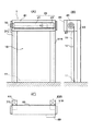
図4は、本発明の実施の形態に係るシートシャッターの全体構造を説明するための図であり、図4(A)は正面図、図4(B)は模式的側面断面図、図4(C)は平面図である。
シートシャッター1は、シート10と、同シート10を巻き上げ・巻き下げするローラ組立体20と、フレーム30等から構成される。フレーム30は、左右のレールボックス31L、31Rと、左右レールボックス31の上端間に掛け渡された本体ボックス81を有する。左右レールボックス31の間をシャッター開口という。図4(B)、図4(C)に示すように、左右のレールボックス31及び本体ボックス81は、左右の柱83L、83Rで支持されている。
Hereinafter, embodiments of the present invention will be described in detail with reference to the drawings.
First, the overall structure of the sheet shutter of the present invention will be described.
4A and 4B are diagrams for explaining the entire structure of the sheet shutter according to the embodiment of the present invention. FIG. 4A is a front view, FIG. 4B is a schematic side sectional view, and FIG. C) is a plan view.
The
シート10は、パイプのないフラットシートである。このようなシートは、例えば、塩ビやポリエステル等の合成樹脂で作製される。シート10の一面の下端には、シート10の幅方向に渡ってフラットバー11が固定されている。フラットバー11はシート10の巻き下げ時の重りとなるもので、鋼帯等で作製され、所定の重量を有する。
The
本体ボックス81の下面には、同ボックスの幅方向に渡って、シート10が出し入れされる開口87が開けられている。同ボックス81内には、ローラ組立体20が、シート10の幅方向に渡って配置されている。ローラ組立体20は、シート10とほぼ同じ幅を有するロータパイプ21と、同パイプ21を回転させるモータ23(減速機付き)を備える。ロータパイプ21には、シート10の上端が固定されている。モータ23が一方向に回転すると、シート10が本体ボックス81の開口87からロータパイプ21の外周に巻き上げられて、シャッター開口が開く。そして、モータ23が反対方向に回転すると、シート10がロータパイプ21の外周から本体ボックス81の開口87を通って垂下するように巻き下げられて、シャッター開口が閉じられる。
An
本体ボックス31の表側の面には、図4(C)に示すように、コントロールボックス89が取り付けられている。このコントロールボックス89には、モータ23の回転等を制御する制御回路等が収容されている。なお、コントロールボックス89の取り付け位置は前述の位置に限らない。
A
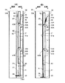
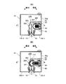
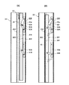
図1は、本発明の第1の実施の形態に係るシートシャッターのレールボックスの構造を示す図であり、図1(A)はシャッター開時の側面断面図、図1(B)はシャッター閉時の側面断面図である。各図において、レールボックスの右側を表側、左側を裏側とする。
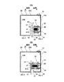
図2は、図1のレールボックスの構造を示す図であり、図2(A)はシャッター開時の平面断面図、図2(B)はシャッター閉時の平面断面図である。各図において、レールボックスの右側を表側、左側を裏側とする。
図3は、図1のシートシャッターの全体の構造を示す図であり、図3(A)はシャッター開時の平面断面図、図3(B)はシャッター閉時の平面断面図である。各図において、シート10の下側を表側、上側を裏側とする。
1A and 1B are views showing the structure of a rail shutter rail box according to a first embodiment of the present invention. FIG. 1A is a side sectional view when the shutter is opened, and FIG. It is side surface sectional drawing at the time. In each figure, the right side of the rail box is the front side and the left side is the back side.
2A and 2B are diagrams showing the structure of the rail box of FIG. 1, FIG. 2A is a plan sectional view when the shutter is open, and FIG. 2B is a plan sectional view when the shutter is closed. In each figure, the right side of the rail box is the front side and the left side is the back side.
3A and 3B are diagrams showing the overall structure of the sheet shutter of FIG. 1, FIG. 3A is a plan sectional view when the shutter is open, and FIG. 3B is a plan sectional view when the shutter is closed. In each figure, the lower side of the
図1、図2を参照してレールボックスの構造を説明する。
レールボックス31は、図2に示すように、断面が正方形の中空のボックス本体33を有する。ボックス本体33は、表壁33a、裏壁33b、内壁33c、外壁33dからなる。内壁33cには、シート10の幅方向端部が挿通される、上下に延びるスリット状の案内部35が形成されている。このシート案内部35により、内壁33cは裏部33c−1と表部33c−2とに分けられている。案内部35の裏側には、内壁裏部33c−1からほぼ直角にボックス本体33内の中央まで延び、その後やや裏方向に直角に延びるシート密着部37が設けられている。図1に示すように、シート密着部37の下端には、後述するアームが出入りするための開口38が開けられている。このシート密着部37の内側において、案内部35を隔てて対向する部分には、図2に示すように、内壁表部33c−2からほぼ直角にボックス本体33内に延びる縁部39が設けられている。
The structure of the rail box will be described with reference to FIGS.
As shown in FIG. 2, the
図2に示すように、この例では、ボックス本体33は、外壁33d、裏壁33b、内壁裏部33c−1とシート密着部37とが、一つの部材(板)を折り曲げ加工して作製されている。そして、表壁33a、内壁表部33c−2と縁部39とが、一つの部材(板)を折り曲げ加工して作製されている。そして、各部材を表壁33aと外壁33dとの交差部をビス41により固定して、ボックス本体33を形成している。
As shown in FIG. 2, in this example, the
次に、図1、図2を参照して、シートの閉限時にシートの固定及びシート案内部の通気性低減を行うシート押し当て機構50について説明する。
シート押し当て機構50は、図2に示すように、ボックス本体33内の、表壁33aと、内壁表部33c−2と縁部39とで囲まれる位置に配置されている。同機構50は、シート10に押し当てられる押し当て部材51と、ボックス本体33に固定されるベース部材53A、53Bと、このベース部材53と押し当て部材51を連結する二対のリンクバー55A、55B、及び、バネ59を有する。
Next, with reference to FIGS. 1 and 2, a sheet
As shown in FIG. 2, the
上下ベース部材53は、図2に示すように断面がコの字状で、図1に示すようにボックス本体33の長さ方向に延びるチャンネル状の部材である。図1に示すように、上下ベース部材53A、53Bは、チャンネルの開口が裏側を向くように表壁33aの内面に固定されている。
The upper and
押し当て部材51は、この例では、図2に示すように断面がコの字状で、図1に示すように、ボックス本体33の長さ方向に延びるチャンネル状の部材である。図1に示すように、押し当て部材51は、チャンネル開口がベース部材53のチャンネル開口に対向するように配置されている。押し当て部材51の長さは、シャッター1の開口部の高さよりやや短い。また、押し当て部材51の下端には、延長部材61が接続部材62で接続されている。延長部材61の奥行きD1は押し当て部材51の奥行きD2よりも、シート10のフラットバー11の厚み程度短い。
なお、図1においては、延長部材61の高さ(長さ)は、押し当て部材51の高さの1/4程度であるが、実際には、延長部材61の高さは、シート10のフラットバー11の高さより高い範囲内で、できるだけ低い(短い)ことが好ましい。
In this example, the pressing
In FIG. 1, the height (length) of the
延長部材61の下端には、裏側へ延びるアーム(押し下げ部材)63が設けられている。アーム63の長さは、案内部35の幅よりやや広い程度である。このアーム63は、シート密着部37の下部に開けられた開口38内に突き出ている。
At the lower end of the
押し当て部材51は、図1に示すように、上下のリンクバー対55A、55Bによって上下のベース部材53A、53Bに連結している。上リンクバー対55Aは、上ベース部材53Aと押し当て部材51の上部とを連結し、下リンクバー対55Bは、下ベース部材53Bと押し当て部材51の下部とを連結している。上下リンクバー55A、55Bの一端は、上下ベース部材53A、53Bの側壁間に掛け渡されたピン65A、65Bに回動可能に接続しており、他端は、押し当て部材51の上部及び下部の側壁間に掛け渡されたピン67A、67Bに回動可能に接続している。
As shown in FIG. 1, the pressing
上下一対のリンクバー55A、55Bの長さは等しく、押し当て部材51の上下のピン67A、67B間の距離と上下ベース部材53A、53Bのピン65A、65B間の距離は等しい。この上下のリンクバー55A、55B及び押し当て部材51は平行リンク機構を構成し、押し当て部材51は垂直の姿勢を保ったまま、ベース部材53に対してスイングするように駆動される。
The lengths of the pair of upper and
各リンクバー55が、ピン65を中心にして図1の時計方向に回転すると、図1(A)に示すように、押し当て部材51がベース部材53方向に移動し、同部材51の各側壁の端部がベース部材53の各側壁の端部にほぼ当接する。以降の説明において、押し当て部材51がベース部材53に当接した状態及び位置を、押し当て部材51の離れ限と言う。
一方、各リンクバー55が、ピン65を中心にして図の反時計方向に回転すると、図1(B)に示すように、押し当て部材51がベース部材53から裏方向に離れて、押し当て部材51の裏側の面(押し当て面51a)が、シート密着面37にほぼ当接する。同時に、押し当て部材51の下端(アーム63)が地面付近に達する。以降の説明において、押し当て部材51がシート密着面37に押し当てられた状態及び位置を、押し当て部材51の押し当て限と言う。
When each
On the other hand, when each
また、押し当て部材51と上ベース部材53Aとは、バネ59で連結されている。バネ59は、上ベース部材53Aの上部に植設されているピン69と、押し当て部材51の上部に植設されているピン67Aとの間に掛け渡されている。このバネ59は、上リンクバー55Aを、ピン65Aを中心にして図1の時計方向に回転させるよう付勢している。つまり、押し当て部材51を図1の右方向に移動させて、離れ限に維持するように付勢している。このときのバネ59の状態を基準状態という。
The pressing
この押し当て部材51の離れ限においては、図1(A)、図2(A)に示すように、同部材51の押し当て面51aと、ボックス本体33のシート密着面37との間に、案内部35の開口とほぼ等しい幅のスキマW1が開いている。また、図1に示すように、押し当て部材51のアーム63には負荷がかかっておらず、同アーム63と地面との間には、所定のスキマW2が開いている。
In the separation limit of the pressing
一方、押し当て部材51のアーム63に下方への力が加わると、図1に示すように、各リンクバー55がピン65を中心として反時計方向に回転する。そして、押し当て部材51が図1の左方向に、押し当て限まで移動する(図1(B)、図2(B)の状態)。同時に、バネ59が伸びて伸張状態となる。
On the other hand, when a downward force is applied to the
次に、このシートシャッター1の開閉時の押し当て機構50の動作について説明する。 図1(A)、図2(A)に示すように、シート10が完全に巻き上げられている状態(以下、シート全開状態という)では、アーム63を下方に押す力が存在しておらず、押し当て部材51は離れ限に位置している。つまり、押し当て部材51の押し当て面51aとボックス本体33のシート密着面37との間に、案内部35と同じ幅のスキマW1が開いている。シート10がシート全開状態から巻き下げられる間、シート10の幅方向端部は案内部35及びこのスキマW1のほぼ中央を通って下降する。
Next, the operation of the
そして、シート10が、同シート下端部のフラットバー11がアーム63に当るまで巻き下げられると、フラットバー11はある程度の重量を持っているため、アーム63がフラットバー11により押し下げられる。アーム63がほぼ地面に接するまで押し下げられると、シート10は、同シート下端部(フラットバー11)が最下部(ほぼ地面上)まで巻き下げられる(以下、シート全閉状態という)。すると、バネ59が伸びてリンクバー55が図1の反時計方向に回転し、押し当て部材51は押し当て限に移動する。(図1(B)、図2(B)の状態)。
When the
押し当て限においては、シート10はボックス本体33のシート密着面37と押し当て部材51の押し当て面51aとの間に挟み込まれる。これにより案内部(開口)35が塞がれて、図3(B)に示すように、シート10で画された2つの空間からボックス本体33内に空気が侵入しにくくなり、両空間の気密性を高めることができる。また、フラットバー11はある程度の重量を有するため、シート10の幅方向端部は押し当て部材51によってある程度の力でシート密着面37に押し当てられている。このためシート10の幅方向両端をボックス本体33から外れないように保持でき、シート10に耐風圧力を与えることができる。
In the pressing limit, the
なお、図1(B)に示すように、シート10のフラットバー11は、押し当て部材51から延びる延長部材61の裏側の面と、ボックス本体33のシート密着面37との間のスキマS内に位置する。そして、延長部材61は押し当て部材51よりも奥行きが短いので、延長部材61の部分においては、シート10はシート密着面37に対して押されていない。しかし、延長部材61は長さ(高さ)が短い(例えば、フラットバー11の高さよりやや高い程度)ため、フラットバー11の剛性によりシート10が幅方向に撓むこともない。
As shown in FIG. 1B, the
シート10が全閉状態から巻き上げられると、同シート10とともにフラットバー11が上昇してアーム63を下方に押す力が徐々に解除される。すると、バネ59が縮み始めて、リンクバー55が図1の時計方向に回転し、押し当て部材51は離れ限に移動する。(図1(A)、図2(A)の状態)。なお、シート10が上昇するとき、押し当て部材51が急にバネ59で付勢されてベース部材53に向かって跳ね上がるようなことがないように、バネ59の張力やフラットバー11の重量等が決められている。
When the
シート10が所定の高さ巻き上げられると、フラットバー11はアーム63から完全に離れ、押し当て部材51は完全にベース部材53方向へ移動する。これにより、押し当て面51aとシート密着面37との間のスキマW1が開き、図3(A)にも示すように、シート10の幅方向端部はこのスキマW1と案内部35を通って上昇可能となる。
When the
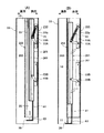
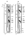
図6は、本発明の第2の実施の形態に係るシートシャッターのレールボックスの構造を示す図であり、図6(A)はシャッター開時の平面断面図、図6(B)はシャッター閉時の平面断面図である。各図において、レールボックスの右側を表側、左側を裏側とする。
図7は、同じく第2の実施の形態に係るシートシャッターのレースボックスの構造を示す図であり、図7(A)は図6(A)のA−A断面図、図7(B)は図6(B)のB−B断面図である。各図において、レールボックスの右側を表側、左側を裏側とする。
6A and 6B are views showing the structure of the rail shutter rail box according to the second embodiment of the present invention. FIG. 6A is a plan sectional view when the shutter is open, and FIG. 6B is the shutter closed. It is a plane sectional view at the time. In each figure, the right side of the rail box is the front side and the left side is the back side.
FIGS. 7A and 7B are views showing the structure of a race box for a sheet shutter according to the second embodiment. FIG. 7A is a cross-sectional view taken along the line A-A in FIG. 6A, and FIG. It is BB sectional drawing of FIG.6 (B). In each figure, the right side of the rail box is the front side and the left side is the back side.
この例のシートシャッターは、実施例1のシートシャッターに対して、
(1)シート押し当て機構の押し当て部材の形状を改良して、シャッター閉時の押し当て部材によるシート押し当てを強化した点、
(2)レールボックスのボックス本体の案内部の構造とシート端部の形状を改良して、シート端部のレールボックスからの抜けを防止した点、
で異なる。以下、主にこれらの点について説明する。以下の説明において、実施例1のシートシャッターと同様の構成・作用を有する部材は実施例1と同じ符号を付し、説明を省略する。
The sheet shutter of this example is compared with the sheet shutter of Example 1.
(1) The shape of the pressing member of the sheet pressing mechanism has been improved to strengthen the sheet pressing by the pressing member when the shutter is closed,
(2) The structure of the guide portion of the box body of the rail box and the shape of the seat end have been improved to prevent the seat end from coming off the rail box,
It is different. Hereinafter, these points will be mainly described. In the following description, members having the same configurations and functions as those of the sheet shutter of the first embodiment are denoted by the same reference numerals as those of the first embodiment, and description thereof is omitted.
まず、この例のシートシャッターの押し当て機構250について説明する。
このシート押し当て機構250は、押し当て部材が、シート端部に表側から当てられる表当て板251と、同部に裏側から当てられる裏当て板253とを含む。両当て板251、253は、ボックス本体33内に、シート案内部35を挟んで対向するように配置されて、同案内部35の長手方向に延びている。表当て板251は、上下ベース部材53A、53Bにリングバー対55A、55Bによって連結している。裏当て板253は、この例では、ボックス本体33の外壁33aに固定されて、ボックス本体33内のほぼ中央に延びている。
First, the sheet shutter
In the sheet
表当て板251の、裏当て板253に対向する面は、横断面が三角形の凸面261となっている。そして、裏当て板253の、表当て板251に対向する面は、横断面が三角形の凹面263となっている。図6(B)に示すように、表当て板251が裏側方向に駆動される(押される)と、それらの当て板251、253の凸面261と凹面263はシート10を挟んで係合する(嵌り合う)。なお、係合時に、凸面261の先端の角が、凹面263の隅により強く当るよう、両面261、263の傾斜を調整することもできる。
The surface of the
表当て板251は、実施例1のシートシャッターと同様の平行リンク機構により、垂直姿勢を保ったまま、上下ベース部材53に対して、押し当て限と離れ限との間をスイングするように駆動される(押し当て限とは、表当て板251と裏当て板253とが係合した状態をいい、離れ限とは、表当て板251が裏当て板253からベース部材53方向に離れた状態という)。押し当て限においては、シート10の端部は、表当て板251の凸面261と裏当て板253の凹面263との間に挟まれている。このようにシート端部を両側から凹凸面で挟むことにより、同部を両側から平面で挟む場合に比べて、シート10をよりしっかりと挟むことができる。あるいは、シート10の端部が折れ曲がるように保持されるので、シート10と両当て板の凸面261と凹面263との摩擦力が増し、シート端部のボックス本体33からの抜けに対する耐力が向上する。これにより、シート10のボックス本体33からの抜けをより確実に防止できる。さらに、シート10の両端部を表裏側から各当て板251、253で挟んでいるため、シート10の表裏側の気密性をより高めることができる。
The
次に、樹脂ガイドについて説明する。
図8は、図7の一部を拡大して示す図であり、図8(A)は図7(A)の一部拡大図、図8(B)は図7(B)の一部拡大図である。
この例のシートシャッターのボックス本体33においては、シート案内部35の両側の内側壁33c−1、33c−2に、樹脂ガイド280を取付けるための縁部271が形成されている。この縁部271は、内側壁33c−1、33c−2からほぼ直角にボックス本体33内へ延びるように形成されている。
Next, the resin guide will be described.
8 is an enlarged view of a part of FIG. 7. FIG. 8 (A) is a partially enlarged view of FIG. 7 (A), and FIG. 8 (B) is a partially enlarged view of FIG. 7 (B). FIG.
In the
樹脂ガイド280は、ボックス本体33の縁部271を囲んで同部に取付けられる基部281と、この基部281から案内部35内に突き出してシート10に接するヒレ部283を有する。ヒレ部283は、基部281(ボックス本体の縁部271)に対して、約30°の角度で案内部35内を斜め奥方向に延びている。また、ヒレ部283の外側(シート案内部側)の面には、同部の上下方向に延びる複数の凸部285が形成されている。このような樹脂ガイド280は、例えばポリエチレンで作製される。
The
一方、シート10の幅方向両端部には、シートの幅方向内側に向けて突き出た干渉部(折り返し部)15が設けられている。この例では、シート10の幅方向両端を折り返し線で内側に折り返して、折り返し片をシート本体に重ね、折り返し線から所定の寸法の部分を熱融着している。折り返し部15は、この熱融着部の端からシート10の幅方向内側に向けて延びている。一例として、熱融着部の幅は約25mm、折り返し部15の幅は約10mmである。
On the other hand, at both ends in the width direction of the
このような樹脂ガイド280を設けることにより、シート端部には表裏側から樹脂ガイド280のヒレ部283が密着するため、シート全閉時での案内部の気密性が向上する。なお、ヒレ部283の外側の面(シートに密着する面)には、上下方向に延びる複数の凸部285が設けられているので、シートの上げ下げ時の摩擦抵抗力を低減できる。
By providing such a
シート10の表側と裏側の空間での圧力の変化などにより、シート10がどちらかの側へ引かれると、シート端部は、図8(B)の矢印で示すように、ボックス本体33から引き出されようとする。このとき、引き出されるシート10の折り返し部15とシート本体10との間に樹脂ガイド280のヒレ部283が入り込み、ヒレ部283が引っ掛かって抵抗となるので、シート端部はボックス本体33から抜け出にくくなる。
When the
図9は、実施例2の変形例を示す図である。
図9(A)に示すシート押し当て機構250´は、裏当て板253の凹面265に高摩擦材料で作製された部材265(例えばラバーシート)が貼られている。このラバーシート265により、シート10と裏当て板253の間の摩擦が増えるため、シート10の抜け防止にさらに有効である。
FIG. 9 is a diagram illustrating a modification of the second embodiment.
In the sheet
また、この例では、シート10の折り返し部15が、シート10の裏側に形成されている。そして、シート10の裏側に取り付けられている樹脂ガイド280のみにヒレ部283が形成されて、シート10の表側に取り付けられている樹脂ガイド280にはヒレ部が形成されていない。このように、片側の樹脂ガイド280のみにヒレ部283を設けることにより、シート10の上げ下げ時にシート10にかかる摩擦抵抗力を減らして、シート10の上げ下げをよりスムーズに行うことができる。
In this example, the folded
図9(B)に示すシート押し当て機構250´´は、表当て板251及び裏当て板253の各対向面に、高摩擦材料で作製された部材266、267(例えばラバーシート)が貼られている。この方法によっても、シャッター閉時に、シート10と表当て板251及び裏当て板253との摩擦力が増えるため、両当て板に凹面と凸面を設けなくてもシート10の抜け防止に有効である。なお、ラバーシートの表面に互いに噛み合う凹凸を形成してもよい。
In the sheet
以上説明したように、この例においては、シート端部を、表裏の当て板251、253の凸面261と凹面263で挟むこと、及び、樹脂ガイド280を設けるとともに同樹脂ガイド280と干渉する折り返し部15をシート端部に設けることにより、シャッター閉時でのシート端部のボックス本体33からの抜け耐力が一層向上する。
As described above, in this example, the sheet end is sandwiched between the
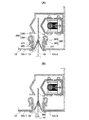
図10は、本発明の第3の実施の形態に係るシートシャッターのレールボックスの構造を示す図であり、図10(A)はシャッター開時の平面断面図、図10(B)はシャッター閉時の平面断面図である。
図11は、同じく第3の実施の形態に係るシートシャッターのレースボックスの構造を示す図であり、図11(A)は図10(A)のC−C断面図、図11(B)は図10(B)のD−D断面図である。
FIGS. 10A and 10B are views showing the structure of a rail shutter rail box according to the third embodiment of the present invention. FIG. 10A is a plan sectional view when the shutter is open, and FIG. It is a plane sectional view at the time.
11A and 11B are views showing the structure of a seat shutter race box according to the third embodiment. FIG. 11A is a cross-sectional view taken along the line CC in FIG. 10A, and FIG. It is DD sectional drawing of FIG. 10 (B).
この例のシートシャッターは、実施例2のシートシャッターに対して、シート押し当て機構の構造を変更した点(当て板駆動用アクチュエータを設けた点)で異なる。
以下、主にシート押し当て機構について説明する。
The sheet shutter of this example is different from the sheet shutter of Example 2 in that the structure of the sheet pressing mechanism is changed (the point plate driving actuator is provided).
Hereinafter, the sheet pressing mechanism will be mainly described.
この例のシートシャッターのシート押し当て機構350は、表当て板251の駆動にソレノイド(アクチュエータ)351を使用する。つまり、図11に示すように、表当て板251と上ベース部材53Aとを、バネではなくソレノイド351で連結している。このようにソレノイド351を設けることにより、表当て板251の下部の延長部材61やアーム63(図7参照)が不要になり、表当て板251をボックス本体33のほぼ全長に渡って延ばすことができる。さらに、裏当て板253にアームが入り込む開口38(図7参照)を設ける必要がなくなる。ただし、表当て板251には、シート10の下段パイプ(又はフラットバー)が入り込むための凹部(図示されず)が形成されている。
In this example, the sheet
ソレノイド351は、シート全閉(シート10が案内部35内を最下部まで下降した状態)を検出するセンサによって駆動される。シート全閉以外の状態(シート全開状態、及び、シートが最下部に達する直前までの状態)では、ソレノイド351は、表当て板251を離れ限に位置するように駆動されている。そして、シート全閉をセンサが検出すると、ソレノイド351は、表当て板251を押し当て限に向かうように駆動する。
The
実施例2では、図7に示すように、シート10の下端にフラットバー11を設けて、同バー11が表当て板251のアーム63に当たってアーム63がフラットバー11の自重で押し下げられることにより、表当て板251をバネ59の力に抗してシート方向に移動させていた。そして、シート全閉状態においては、バネ59は表当て板251をベース部材53の方向に付勢するように作用していた。このため、フラットバー11には、バネ59の抗力に対抗するだけの程度の重量が必要になり、その結果シート全体の重量が増加していた。しかし、この例では、シート全閉(シート10が案内部35内の最下部まで下降したこと)をセンサで検知して、表当て板251をソレノイド351で駆動するため、フラットバーを軽量化できる。
In Example 2, as shown in FIG. 7, the
また、上述のように延長部材61やアーム63を設ける必要がないため、表当て板251の長さを、ボックス本体33のほぼ全長の長さとすることができる。このため、実施例2ではシート10の下端部は両当て板251、253で挟まれていなかったが、この例では、ボックス本体33内のシート10をほぼ全長に渡って両当て板251、253の間に挟んで固定できる。
In addition, since it is not necessary to provide the
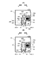
図12は、本発明の第4の実施の形態に係るシートシャッターのレールボックスの構造を示す図であり、図12(A)はシャッター開時の平面断面図、図12(B)はシャッター閉時の平面断面図である。
図13は、同じく第4の実施の形態に係るシートシャッターのレースボックスの構造を示す図であり、図13(A)は図12(A)のE−E断面図、図13(B)は図12(B)のF−F断面図である。
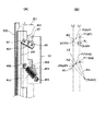
図14は、第4の実施の形態のシートシャッターの表当て板を動作させる際におけるリンクバーとバネの動きを説明する図であり、図14(A)はリンクバーとバネを示す図であり、図14(B)はリンクバーとバネの動作の軌跡等を示す図である。図14(A)において、表当て板251の押し当て限の位置を実線で示し、同板251の離れ限の位置を想像線(二点鎖線)で示す。
12A and 12B are diagrams showing the structure of the rail shutter rail box according to the fourth embodiment of the present invention. FIG. 12A is a plan sectional view when the shutter is open, and FIG. It is a plane sectional view at the time.
FIGS. 13A and 13B are views showing the structure of a seat shutter race box according to the fourth embodiment. FIG. 13A is a cross-sectional view taken along line EE in FIG. 12A, and FIG. It is FF sectional drawing of FIG. 12 (B).
FIG. 14 is a view for explaining the movement of the link bar and the spring when the seating plate of the sheet shutter according to the fourth embodiment is operated. FIG. 14A is a view showing the link bar and the spring. FIG. 14 (B) is a diagram showing the trajectory of the operation of the link bar and the spring. In FIG. 14A, the position of the pressing limit of the
この例のシートシャッターは、実施例2のシートシャッターに対して、シート押し当て機構のバネ453等の構成が異なる。
この例では、重力やバネの力の総合作用によって、表当て板251の押し当て限(表当て板251が裏当て板253に押し当てられている状態、図12(B)、図13(B))においては、表当て板251が裏当て板253に押し付けられるように付勢されているとともに、同板251の離れ限(表当て板251が裏当て板253から離れてベース部材53方向に引き寄せられている状態、図12(A)、図13(A))においては、表当て板251が裏当て板253から引き離されるように付勢されている。一方、実施例2においては(実施例1でも同様)、押し当て限においてバネ59が押し当て板251を引く力が最大となって、強い力で押し当て板251が裏当て板253から離れる方向に付勢される構成となっている。このため、シート全閉時に、表当て板251を裏当て板253に十分な力で押し当てられるようにするためには、バネ59の付勢力に抗するだけの大重量を有するフラットバー11(シート下端部の重り)でアーム63を押しようにする必要があり、その結果シート10全体が重くなってしまう。そうなると、当然シート巻き上げモータの容量も大きくなる。
The sheet shutter of this example is different from the sheet shutter of Example 2 in the configuration of the
In this example, due to the combined action of gravity and spring force, the pressing limit of the front plate 251 (the state in which the
これに対して、本実施例では、バネの付勢力を、表当て板を押し当て限と離れ限の双方に位置させる力として利用している。つまり、表当て板押し当て限においては、表当て板251の自重と、バネの、表当て板251を裏当て板253に押し当てる方向の付勢力との総合作用によって、シート10を表当て板251と裏当て板253の間に挟持させている。また、表当て板の離れ限においては、バネは、表当て板を裏当て板から引き離す方向の付勢力を発揮している。このように構成することにより、シート重量の増加と、シート巻き上げ・巻き下げ用モータの容量の増加を抑制しつつ、表当て板のスムーズな作動と、シートの幅方向両端部のレールボックスからの抜け防止を図ることができる。
On the other hand, in the present embodiment, the biasing force of the spring is used as a force for positioning the front abutting plate at both the pressing limit and the separation limit. In other words, at the front plate pressing limit, the
図13に示すように、表当て板251と上下のベース部材53とは、各々上下リンクバー451で連結している。各リンクバー451の基端(ベース部材53の側)は、ベース部材53に植設された基端ピン65に連結しており、同バーの先端(反ベース部材側)は、表当て板251に植設された先端ピン67に連結している。ここで、図14(A)の想像線に示すように、表当て板251の離れ限(二点鎖線の状態)では、リンクバー451の先端ピン67は、基端ピン65よりもシート側(図の左側)に位置する(例えば、ピン65を中心として、ピン65を通る垂線から5°の位置)。このため、表当て板251を離れ限から押し当て限方向に駆動するときに、リンクバー451がスムーズに回りやすい。というのは、基端ピン65と先端ピン67とが垂線上にあると、表当て板251がアーム63を介して下に押されたときに、リンクバー451の回動がロックされるおそれがあるからである。
As shown in FIG. 13, the
これらの表当て板251、上下のベース部材53、上下リンクバー451は平行リンク機構を構成している。上下リンクバー451が、各々基端ピン65を中心として回転すると、表当て板251は垂直の姿勢を保ったまま、各ベース部材53に対して、表当て板251の押し当て限と離れ限との間をスイングするように移動する。この例では、表当て板251が押し当て限と離れ限との間をスイングする間、各リンクバー451は約55°回転する。
These
また、表当て板251と上下ベース部材53との間には上下のバネ453A、453Bが配設されている。上下バネ453の基端(ベース部材53の側)は、上下ベース部材53に植設された基端ピン455に連結され、先端(反ベース部材側)は、表当て板251に植設された先端ピン456に連結されている。
Further, upper and
図14(B)を参照して、リンクバー451とバネ453の動きを説明する。
まず、図14(B)と図14(A)の関連を説明する。
図14(B)の上方に示す点CLは、リンクバー451(図14(A)参照)の基端ピン65の中心を示す。そして、点Pは、リンクバー451の先端ピン67の中心を示し、点P1は、表当て板の離れ限における同ピン67の中心、点P3は、表当て板の押し当て限における同ピン67の中心を示す。点P2は、表当て板の離れ限と押し当て限との中間における同ピン67の中心を示す。線分RLは、リンクバー451の両ピン65、67間の距離を示す。
平行リンク運動時に、点Pは、点P1と点P3との間を、点CLを中心として回転半径RLで移動する。このときの点Pの回転軌跡をR2とする。
With reference to FIG. 14B, the movement of the
First, the relationship between FIG. 14B and FIG.
A point CL shown in the upper part of FIG. 14B indicates the center of the
During the parallel link movement, the point P moves between the point P1 and the point P3 with the rotation radius RL around the point CL. The rotation locus of point P at this time is R2.
また、図14(B)の下方に示す点CSは、バネ453(図14(A)参照)の基端ピン455の中心を示す。そして、点P´は、バネ453の先端ピン456の中心を示し、点P1´は、表当て板の離れ限における同ピン456の中心、点P3´は、表当て板の押し当て限における同ピン456の中心を示す。点P2´は、表当て板の離れ限と押し当て限との中間における同ピン456の中心を示す。線分RSは、点P1´、点P3´におけるバネ453の両ピン455、456間の距離(以下、バネ453の基準長さともいう)を示す。
A point CS shown below FIG. 14B indicates the center of the
図14(A)、図14(B)を参照して、バネ453の作用と、同バネ453の各ピン455、456の位置関係を説明する。
このバネ453は、先端ピン456がいずれの位置にある場合でも、引き勝手(縮もうとする方向)に作用している。
バネ453の先端ピン456(点P´)は、平行リンク運動中、点P1´と点P3´との間を、回転軌跡をR2´に沿って移動する。この回転軌跡R2´は、リンクバー451の先端ピン67(点P)の回転軌跡R2と同じ曲率の円弧である。平行リンク運動においては、表当て板251はベース部材53と平行に、押し当て限と離れ限との間を移動するので、点P1と点P1´、点P3と点P3´、点P2と点P2´も、各々1本の垂線上にある。
With reference to FIGS. 14A and 14B, the action of the
The
The tip pin 456 (point P ′) of the
一方、バネ453の基端ピン455(点CS)は、点P1´、点P3´を結ぶ線分の中心を通る垂線L3上であって、線分RS(点P1´、点P3´におけるバネ453の両ピン456、455間の距離、基準長さ)が、線分RL(リンクバー451の両ピン65、67間の距離)よりも大となる位置に位置している。
この結果、図14(B)に示すように、点P1´と点P3´との間を、バネ453が基準長さRSの半径で(つまり、バネ453が伸び縮みなく)、基端ピン455を中心として回転すると仮定したときの、先端ピン456の想像上の回転軌跡R1は、基端ピン456の実際の回転軌跡R2´の内側に位置する。つまり、点P1´と点P3´の間で、バネ453が引き勝手に作用する力の大きさは、点P1´と点P3´の中央の点P2´で最も大きい。
On the other hand, the base end pin 455 (point CS) of the
As a result, as shown in FIG. 14B, between the point P1 ′ and the point P3 ′, the
このバネ453の付勢力は、リンクバー451の先端ピン67に作用する。
表当て板の離れ限においては、同ピン67には、バネ453の付勢力の内、リンクバー451を基端ピン65に対して図の時計方向に回転させる方向の要素が主に作用する。この結果、表当て板251はベース部材53に押し当てられている。
The biasing force of the
At the separation limit of the front cover plate, an element in the direction of rotating the
一方、押し当て限においては、同ピン67には、バネ453の付勢力の内、リンクバー451を基端ピン65に対して図の反時計方向に回転させる方向の要素が主に作用する。この結果、表当て板251は裏当て板253に押し当てられている。ここで、表当て板251の自重は、基端ピン65を中心とするモーメント(図14において反時計回りのモーメント)を生むので、この自重モーメントが表当て板251を裏当て板253に、すなわち、シート10に押し当てる付勢力となる。すなわち、押し当て限においては、表当て板251はバネ453の付勢力と同板251の自重による力の総合的な作用によってシート10が両当て板間に挟まれる。
On the other hand, in the pressing limit, an element in the direction of rotating the
なお、上述のように、点P1´と点P3´の間で、バネ453が引き勝手に作用する力の大きさは、点P1´と点P3´の中央点P2´で最も大きいので、バネ453がリンクバー451の先端ピン67に及ぼす付勢力の方向は中央点P2´で逆転する。
Note that, as described above, the magnitude of the force that the
次に、シート押し当て機構全体の一連の作用を説明する。
シート全開時(シート10の下端部のフラットバー11がボックス本体の案内部35内の最上部まで上昇した状態)では、表当て板251は離れ限にある。離れ限においては、上述のように、表当て板251はバネ453によってベース部材53の方向に付勢されている。この状態からシート10が巻き下げられて、シート下端部のフラットバー11が表当て板251のアーム63に当ると、図13(A)の矢印に示すように、同アーム63が押し下げられる。すると、リンクバー451が、図13(B)の矢印で示すように反時計方向へ回転しようとする。離れ限では、バネ453は、リンクバー451を図の時計方向に回転するように付勢しているが、フラットバー11によるアーム63の押し下げによってリンクバー451を反時計方向へ回転させる力が、バネ453の付勢力よりも強いため、リンクバー451は反時計方向に回転する。さらに、上述のように、各リンクバー451の先端ピン67は、基端ピン65よりもシート側に寄って位置しているため、表当て板251は反時計方向へ回転しやすくなっている。
Next, a series of actions of the entire sheet pressing mechanism will be described.
When the seat is fully open (the state where the
そして、リンクバー451が、回転軌跡R2の中央P2を過ぎるまで回転すると、バネ453は、今度はリンクバー451を図の反時計方向に回転させるように付勢する。
また、上述のように、表当て板251の自重によるモーメントによっても、同板251は裏当て板253の方向(リンクバー451を反時計方向に回転させる方向)に付勢される。
When the
Further, as described above, the
最終的に、シート10の下端部が、案内部35の最下部まで下降する(シート全閉)と、リンクバー451は離れ限から図の反時計方向に所定角度θ(この例では約55°)回転し、表当て板251が裏当て板253に押し当てられて、シート10が両板の間に挟まれる。このとき、表当て板251は、バネ453の付勢力と同板251の自重の総合力によって裏当て板253に押し当てられているため、シート10の端部を十分な力で両板251、253間に挟持させることができる。
Finally, when the lower end portion of the
さらに、表当て板251の押し下げに必要であったシート下端部のフラットバー11を実施例2のフラットバーほどに重くする必要がなく、シート全体を軽量化できる。というのは、実施例1や実施例2では、バネが引き勝手(押し当て板をベース部材の方向に引き寄せる方向)に作用しており、その力に打ち勝ってアームを押し下げる必要がある。このため、アームを押し下げるためのフラットバーの重量が重くなっていた。
Furthermore, it is not necessary to make the
なお、この例では、バネ453の基端ピン455を、垂線L3(点P1´、点P3´を結ぶ線分の中心を通る線)上に設けたが、この位置に限るものではない。
例えば、離れ限においては、リンクバー451の先端ピン67に、バネ453の付勢力の内のベース部材方向へ向かう要素が主に作用し、押し当て限においては、同ピン67に、バネ453の付勢力の内の裏当て板方向への向かう要素が主に作用する範囲内で、バネ453の張力や基準長さ等を設定すればよい。
In this example, the
For example, in the separation limit, an element toward the base member of the urging force of the
図13に示すように、表当て板251の下部には、カム板461を介して、裏当て板方向に延びるアーム63が設けられている。カム板461には、図に示すように、裏当て板253側から表当て板251に向けて斜め下方に延びるカム面463が形成されている。
As shown in FIG. 13, an
シート全閉(表当て板の押し当て限)から、シート10が案内部35内を上昇すると、シート下端部のフラットバー11はやがてカム板461のカム面463に当たる。そしてフラットバー11が同カム面463に沿って上昇するときに、カム板461がフラットバー11に蹴り上げられるように引き上げられる。これにより、リンクバー451がバネ453の力に抗して図の時計方向に回転し始める。そして、リンクバー451の先端ピン67が回転軌跡の中心P2を過ぎると、同バー451は今度は図の時計方向に回転するように付勢されるため、表当て板251は裏当て板253から離れてベース部材53に当接する(表当て板の離れ限)。
When the
図12、図13に示すように、裏当て板253の上部の、表当て板251と干渉しない位置には、表当て板251の方向へ突き出たコマ275が形成されている。上述のように、シート10が全閉から巻き上げられるときには、シート10のフラットバー11が表当て板251のカム板461を蹴り上げることにより、バネ453が表当て板251を離れ限に付勢する。この際、表当て板251が離れ限まで行かないような場合があり得る。そのような場合、シート10が巻き上げられてフラットバー11が開限に達すると、同バー11はコマ275に沿って引き上げられながら、表当て板251の方向に寄せられる。これにより、表当て板251がフラットバー11を介してベース部材53の方向へ押され、同板251は離れ限にまで動く。
As shown in FIGS. 12 and 13, a top 275 protruding in the direction of the
以上説明したように、この例のシートシャッターは、表当て板251の、裏当て板253の方向への押し当てに、表当て板251の自重による力とバネ453の力を利用している。このため、シート10のフラットバー11を重くする必要がなく、シート10の重量を軽量化できる。
As described above, the sheet shutter of this example uses the force of the weight of the
この例においては、バネ453の変わりに、実施例2と同様に、ソレノイド等のアクチュエータと、シャッター閉を検知するセンサを使用することもできる。つまり、シャッター開時には、ソレノイドは、表当て板251をベース部材53方向に引き寄せるように作動している。そして、センサがシャッター閉を検知すると、ソレノイドが、表当て板251を裏当て板253方向に押し出すように作動する。
In this example, instead of the
1 シートシャッター
10 シート 15 折り返し部
11 パイプ 20 ローラ組立体
21 ロータパイプ 23 モータ
30 フレーム 31 レールボックス
33 ボックス本体 33a 前壁
33b 後壁 33c 内壁
33d 外壁 35 シート案内部
37 シート密着部 38 開口
39 縁部 41 ビス
50 シート押し当て機構 51 押し当て部材
53 ベース部材 55 リンクバー
59 バネ 63 アーム(押し下げ部材)
65 ピン 67 ピン
81 本体ボックス 83 柱
87 開口 89 コントロールボックス
100 レールボックス 101 レール案内開口
103 樹脂ガイド 110 シート
111 パイプ
250 シート押し当て機構 251 表当て板
253 裏当て板 261 凸面
263 凹面 271 縁部
280 樹脂ガイド 281 基部
283 ヒレ部 285 凸部
350 シート押し当て機構 351 ソレノイド(アクチュエータ)
451 リンクバー 453 バネ
455、456 ピン 461 カム板
463 カム面
DESCRIPTION OF
65
451
Claims (10)
前記シートは、上下方向中間部分に、シートの幅方向の変形を抑制するための補強部材のないフラットなものであり、
前記レールボックスが、
上下方向に延びる、前記シートの幅方向の端部の挿通されるスリット状の案内部を有するボックス本体と、
該ボックス本体内において上下方向に延びるように設けられた、前記シートが閉限にある場合に前記シートに対して押し当てられる押し当て部材(当て板)と、
を具備することを特徴とするシートシャッター。 A sheet shutter comprising: a sheet that is raised and lowered at an opening of a building and that opens and closes the opening; a means for winding and lowering the sheet; and a rail box that vertically guides both ends in the width direction of the sheet,
The sheet is a flat member having no reinforcing member for suppressing deformation in the width direction of the sheet in the middle portion in the vertical direction,
The rail box is
A box body having a slit-shaped guide portion extending in the vertical direction and inserted through an end portion in the width direction of the sheet;
A pressing member (pad plate) provided to extend in the vertical direction in the box body and pressed against the sheet when the sheet is in a closed limit;
A sheet shutter comprising:
該押し当て部材に接続された、前記シートによって下に押されるアームと、
該アームの下降に伴って回動する、前記押し当て部材に回動可能に連結されたリンクと、
を有することを特徴とする請求項1記載のシートシャッター。 A mechanism for pressing the pressing member (plate) against the sheet,
An arm connected to the pressing member and pressed downward by the sheet;
A link that pivots as the arm descends and is pivotally connected to the pressing member;
The sheet shutter according to claim 1, comprising:
両板の前記シート端部を挟持する面に、互いに係合し合う凹凸が形成されていることを特徴とする請求項1記載のシートシャッター。 The pressing member includes a front plate and a backing plate that are relatively driven so as to be applied to the end portion of the sheet and sandwich the portion,
The sheet shutter according to claim 1, wherein concave and convex portions that engage with each other are formed on a surface that sandwiches the sheet end portion of both plates.
該シート端部が前記ボックス本体の案内部から幅方向中央に向けて引き出されようとしたときに、前記干渉部が前記樹脂ガイドのヒレ部と干渉して、該シート端部の前記ボックス本体からの抜けを防止することを特徴とする請求項5記載のシートシャッター。 An interference portion protruding toward the center of the sheet in the width direction is provided at the end of the sheet,
When the sheet end portion is about to be pulled out from the guide portion of the box body toward the center in the width direction, the interference portion interferes with the fin portion of the resin guide, and from the box body at the sheet end portion. 6. The sheet shutter according to claim 5, wherein the sheet shutter is prevented.
該アームの下降に伴って回動する、前記ボックス本体と前記当て板とに回動可能に連結されたリンクと、
前記ボックス本体と前記当て板との間に配設されたバネと、を有し、
前記シートが閉限にあるときには、前記当て板が前記シートに向かって押し当てる方向に付勢され、
前記シートが開いているときには、前記当て板が前記シートから離れる方向に付勢されることを特徴とする請求項1記載のシートシャッター。 An arm connected to the backing plate and pushed down by the sheet;
A link pivotably connected to the box body and the abutting plate that pivots as the arm descends;
A spring disposed between the box body and the backing plate,
When the seat is in the closed limit, the contact plate is urged in a direction to press against the seat,
The sheet shutter according to claim 1, wherein when the sheet is open, the contact plate is biased in a direction away from the sheet.
Priority Applications (1)
| Application Number | Priority Date | Filing Date | Title |
|---|---|---|---|
| JP2004218519A JP2005290966A (en) | 2004-03-11 | 2004-07-27 | Sheet shutter |
Applications Claiming Priority (2)
| Application Number | Priority Date | Filing Date | Title |
|---|---|---|---|
| JP2004068960 | 2004-03-11 | ||
| JP2004218519A JP2005290966A (en) | 2004-03-11 | 2004-07-27 | Sheet shutter |
Publications (1)
| Publication Number | Publication Date |
|---|---|
| JP2005290966A true JP2005290966A (en) | 2005-10-20 |
Family
ID=35324206
Family Applications (1)
| Application Number | Title | Priority Date | Filing Date |
|---|---|---|---|
| JP2004218519A Pending JP2005290966A (en) | 2004-03-11 | 2004-07-27 | Sheet shutter |
Country Status (1)
| Country | Link |
|---|---|
| JP (1) | JP2005290966A (en) |
Cited By (6)
| Publication number | Priority date | Publication date | Assignee | Title |
|---|---|---|---|---|
| KR100748280B1 (en) * | 2006-02-10 | 2007-08-09 | 강연구 | Shutter Delay Device |
| JP2016138372A (en) * | 2015-01-26 | 2016-08-04 | 三和シヤッター工業株式会社 | Waterproof shutter |
| JP2020094385A (en) * | 2018-12-12 | 2020-06-18 | 文化シヤッター株式会社 | Switchgear |
| IT201900022611A1 (en) * | 2019-12-02 | 2021-06-02 | Marvil Eng S R L | AUTOMATED WAREHOUSE SUPPLIED WITH OXYGEN REDUCING FIRE-FIGHTING SYSTEM. |
| JP2024095160A (en) * | 2022-12-28 | 2024-07-10 | 三協立山株式会社 | Opening device |
| NL2038394B1 (en) * | 2024-08-05 | 2026-02-19 | Bg Door Int B V | Gas-tight roller door device and method for operating such a gas-tight roller door. |
Citations (6)
| Publication number | Priority date | Publication date | Assignee | Title |
|---|---|---|---|---|
| JPS53133453U (en) * | 1977-03-29 | 1978-10-23 | ||
| JPH05179874A (en) * | 1991-12-28 | 1993-07-20 | Toyo Shutter Kk | Sheet slip-off preventing device for sheet shutter |
| JPH1072984A (en) * | 1996-08-29 | 1998-03-17 | Bunka Shutter Co Ltd | Shutter silencer |
| JP2000179253A (en) * | 1998-12-10 | 2000-06-27 | Bunka Shutter Co Ltd | Switchgear |
| JP2002070456A (en) * | 2000-09-04 | 2002-03-08 | Yamazaki Sangyo Kk | Shutter noise suppressor |
| JP2003253976A (en) * | 2002-03-01 | 2003-09-10 | Masaharu Sakata | Sheet shutter device and sheet seal unit used therefor |
-
2004
- 2004-07-27 JP JP2004218519A patent/JP2005290966A/en active Pending
Patent Citations (6)
| Publication number | Priority date | Publication date | Assignee | Title |
|---|---|---|---|---|
| JPS53133453U (en) * | 1977-03-29 | 1978-10-23 | ||
| JPH05179874A (en) * | 1991-12-28 | 1993-07-20 | Toyo Shutter Kk | Sheet slip-off preventing device for sheet shutter |
| JPH1072984A (en) * | 1996-08-29 | 1998-03-17 | Bunka Shutter Co Ltd | Shutter silencer |
| JP2000179253A (en) * | 1998-12-10 | 2000-06-27 | Bunka Shutter Co Ltd | Switchgear |
| JP2002070456A (en) * | 2000-09-04 | 2002-03-08 | Yamazaki Sangyo Kk | Shutter noise suppressor |
| JP2003253976A (en) * | 2002-03-01 | 2003-09-10 | Masaharu Sakata | Sheet shutter device and sheet seal unit used therefor |
Cited By (7)
| Publication number | Priority date | Publication date | Assignee | Title |
|---|---|---|---|---|
| KR100748280B1 (en) * | 2006-02-10 | 2007-08-09 | 강연구 | Shutter Delay Device |
| JP2016138372A (en) * | 2015-01-26 | 2016-08-04 | 三和シヤッター工業株式会社 | Waterproof shutter |
| JP2020094385A (en) * | 2018-12-12 | 2020-06-18 | 文化シヤッター株式会社 | Switchgear |
| JP7128103B2 (en) | 2018-12-12 | 2022-08-30 | 文化シヤッター株式会社 | switchgear |
| IT201900022611A1 (en) * | 2019-12-02 | 2021-06-02 | Marvil Eng S R L | AUTOMATED WAREHOUSE SUPPLIED WITH OXYGEN REDUCING FIRE-FIGHTING SYSTEM. |
| JP2024095160A (en) * | 2022-12-28 | 2024-07-10 | 三協立山株式会社 | Opening device |
| NL2038394B1 (en) * | 2024-08-05 | 2026-02-19 | Bg Door Int B V | Gas-tight roller door device and method for operating such a gas-tight roller door. |
Similar Documents
| Publication | Publication Date | Title |
|---|---|---|
| CN1580479B (en) | Sheet roller shutter door | |
| JP2005290966A (en) | Sheet shutter | |
| JP2017214745A (en) | Overhead door | |
| JP7342327B2 (en) | Deflector mechanism of sunroof device | |
| JP5333553B2 (en) | Waterproof door device | |
| JP5158401B2 (en) | Shutter device | |
| JP4897295B2 (en) | Upper guide structure | |
| JP2015048599A (en) | Sheet shutter | |
| JP2004060307A (en) | Retaining structure of shutter curtain for architectural shutter | |
| JP6425582B2 (en) | Window regulator | |
| JP4668715B2 (en) | Shutter curtain guide structure | |
| JPH0740078Y2 (en) | Panel shutter panel | |
| JP2021075929A (en) | Water cut-off plate and water cut-off structure using the same | |
| TWI869029B (en) | Doors, windows and their screen anti-lifting devices | |
| EP1795693A1 (en) | Crime prevention structure of shutter for building | |
| JP5007553B2 (en) | Waterproof door device | |
| JP2006037596A (en) | Sheet shutter and projection sheet shutter | |
| JP2010196365A (en) | Building shutter | |
| JP3876421B2 (en) | shutter | |
| JP7489843B2 (en) | Sheet Shutter | |
| JP4675789B2 (en) | Screen device | |
| JP2005515327A (en) | See-through window covering actuator device and manufacturing method thereof | |
| JP2008008038A5 (en) | ||
| JP2008008038A (en) | Shutter device | |
| JP2003082887A (en) | Retractable membrane roof structure |
Legal Events
| Date | Code | Title | Description |
|---|---|---|---|
| A621 | Written request for application examination |
Effective date: 20070727 Free format text: JAPANESE INTERMEDIATE CODE: A621 |
|
| A977 | Report on retrieval |
Free format text: JAPANESE INTERMEDIATE CODE: A971007 Effective date: 20100311 |
|
| A131 | Notification of reasons for refusal |
Effective date: 20100316 Free format text: JAPANESE INTERMEDIATE CODE: A131 |
|
| A02 | Decision of refusal |
Effective date: 20100810 Free format text: JAPANESE INTERMEDIATE CODE: A02 |