JP2005291073A - Engine system - Google Patents
Engine system Download PDFInfo
- Publication number
- JP2005291073A JP2005291073A JP2004106452A JP2004106452A JP2005291073A JP 2005291073 A JP2005291073 A JP 2005291073A JP 2004106452 A JP2004106452 A JP 2004106452A JP 2004106452 A JP2004106452 A JP 2004106452A JP 2005291073 A JP2005291073 A JP 2005291073A
- Authority
- JP
- Japan
- Prior art keywords
- catalyst
- temperature
- reducing agent
- fuel ratio
- exhaust gas
- Prior art date
- Legal status (The legal status is an assumption and is not a legal conclusion. Google has not performed a legal analysis and makes no representation as to the accuracy of the status listed.)
- Pending
Links
- 239000003054 catalyst Substances 0.000 claims abstract description 65
- 238000010926 purge Methods 0.000 claims abstract description 39
- 239000000446 fuel Substances 0.000 claims abstract description 17
- 239000003638 chemical reducing agent Substances 0.000 claims abstract description 16
- 239000011593 sulfur Substances 0.000 claims abstract description 12
- 229910052717 sulfur Inorganic materials 0.000 claims abstract description 12
- NINIDFKCEFEMDL-UHFFFAOYSA-N Sulfur Chemical compound [S] NINIDFKCEFEMDL-UHFFFAOYSA-N 0.000 claims abstract description 11
- 230000000630 rising effect Effects 0.000 claims description 2
- 231100000572 poisoning Toxicity 0.000 abstract description 12
- 230000000607 poisoning effect Effects 0.000 abstract description 12
- 239000007789 gas Substances 0.000 description 18
- 238000000034 method Methods 0.000 description 12
- 101000585359 Homo sapiens Suppressor of tumorigenicity 20 protein Proteins 0.000 description 5
- 102100029860 Suppressor of tumorigenicity 20 protein Human genes 0.000 description 5
- QVGXLLKOCUKJST-UHFFFAOYSA-N atomic oxygen Chemical compound [O] QVGXLLKOCUKJST-UHFFFAOYSA-N 0.000 description 4
- 229910052760 oxygen Inorganic materials 0.000 description 4
- 239000001301 oxygen Substances 0.000 description 4
- 230000004913 activation Effects 0.000 description 3
- 238000010586 diagram Methods 0.000 description 3
- 238000000746 purification Methods 0.000 description 3
- 230000001174 ascending effect Effects 0.000 description 2
- 238000009529 body temperature measurement Methods 0.000 description 2
- 238000002347 injection Methods 0.000 description 2
- 239000007924 injection Substances 0.000 description 2
- 238000002485 combustion reaction Methods 0.000 description 1
- 230000006866 deterioration Effects 0.000 description 1
- 238000005259 measurement Methods 0.000 description 1
- 238000012986 modification Methods 0.000 description 1
- 230000004048 modification Effects 0.000 description 1
- 230000008929 regeneration Effects 0.000 description 1
- 238000011069 regeneration method Methods 0.000 description 1
- 238000001179 sorption measurement Methods 0.000 description 1
- 150000003463 sulfur Chemical class 0.000 description 1
- 230000002123 temporal effect Effects 0.000 description 1
- 238000011144 upstream manufacturing Methods 0.000 description 1
Images

Landscapes
- Exhaust Gas After Treatment (AREA)
- Electrical Control Of Air Or Fuel Supplied To Internal-Combustion Engine (AREA)
- Combined Controls Of Internal Combustion Engines (AREA)
Abstract
Description
本発明は、内燃機関の排気に含まれる有害成分や微粒子等を浄化する排気浄化装置に関し、特に、触媒のS被毒を回復させるSパージ運転時の触媒昇温制御に関する。 The present invention relates to an exhaust gas purification device that purifies harmful components, particulates, and the like contained in exhaust gas of an internal combustion engine, and more particularly to catalyst temperature increase control during an S purge operation that recovers S poisoning of a catalyst.
従来、ディーゼルエンジンの排気管にNOx吸蔵触媒が設けられた排ガス浄化装置が知られている。このようなNOx触媒を用いた排ガス浄化装置は、NOx吸蔵触媒には燃料中の硫黄分により硫黄被毒が発生する。この硫黄の除去のため、定期的(例えば5000km走行に1回)に硫黄分放出のSパージ運転を1分程度行う必要がある。Sパージ運転は、600℃以上の触媒温度が必要である。このために排気配管中に軽油を添加したり、ポスト噴射等により還元成分であるHCの供給を行うことでNOx吸蔵触媒の温度を上昇させる技術が知られている(例えば、特許文献1参照)。
上述したエンジンシステムであると次のような問題があった。すなわち、NOx吸蔵触媒が適温に達していない、触媒の劣化が進んでいる等の理由により、供給されたHCがNOx吸蔵触媒で処理されずにNOx吸蔵触媒に吸着するHC被毒が生じる。HC被毒が生じると、NOx吸蔵触媒に酸素が供給されない状態が生じ、HCを供給しつづけても触媒温度は上昇しないため、硫黄分が十分に除去されない虞があった。 The engine system described above has the following problems. That is, HC poisoning occurs in which the supplied HC is adsorbed to the NOx storage catalyst without being treated by the NOx storage catalyst, for example, because the NOx storage catalyst has not reached the proper temperature or the deterioration of the catalyst has progressed. When HC poisoning occurs, there is a state in which oxygen is not supplied to the NOx storage catalyst, and the catalyst temperature does not rise even if HC is continuously supplied, so that the sulfur content may not be sufficiently removed.
図4のグラフD1〜D3は上述した現象を時間経過とともに示す説明図である。すなわち、グラフD1に示すように、Sパージ運転の開始に伴ってHCが一定割合ずつ供給され始める。グラフD3に示すように、当初は触媒温度は上昇するが、HC被毒により酸素が供給されず触媒温度が下降し始めると、グラフD2に示すようにHCスリップ現象が始まる。 Graphs D1 to D3 in FIG. 4 are explanatory diagrams showing the above-described phenomenon over time. That is, as shown in the graph D1, HC starts to be supplied at a constant rate with the start of the S purge operation. As shown in graph D3, the catalyst temperature initially increases. However, when oxygen is not supplied due to HC poisoning and the catalyst temperature starts to decrease, the HC slip phenomenon starts as shown in graph D2.
そこで本発明は、HCを供給して触媒の温度を上昇させるSパージ運転を行う際に、HC被毒による温度上昇不良を防止し、触媒に付着した硫黄分の除去を適切に行うことができるエンジンシステムを提供することを目的としている。 Therefore, according to the present invention, when performing the S purge operation for increasing the temperature of the catalyst by supplying HC, it is possible to prevent a temperature increase failure due to HC poisoning and to appropriately remove the sulfur content adhering to the catalyst. It aims to provide an engine system.
上記課題を解決し目的を達成するために、本発明のエンジンシステムは次のように構成されている。 In order to solve the above problems and achieve the object, the engine system of the present invention is configured as follows.
(1)エンジンの排気通路に設けられ、前記排気通路に流入する排ガス中のNOxを吸蔵し、かつ、前記排ガスの空燃比が理論空燃比以下で還元剤成分が増加したときに再生処理されるするとともに、前記排ガス中のHC,CO成分が増加し、かつ、所定温度まで昇温され空燃比が理論空燃比とされるSパージ運転時に吸着した硫黄分が除去される触媒と、前記排気通路内にHCを含む還元剤成分を供給する還元剤供給手段と、前記触媒の温度を検出する触媒温度センサとを備え、前記還元剤供給手段は、前記Sパージ運転時に還元剤を供給するとともに、所定のタイミングで還元剤供給を所定時間だけ休止することを特徴とする。 (1) Provided in the exhaust passage of the engine, occludes NOx in the exhaust gas flowing into the exhaust passage, and is regenerated when the air-fuel ratio of the exhaust gas is less than the stoichiometric air-fuel ratio and the reducing agent component increases. And a catalyst for removing sulfur adsorbed during an S purge operation in which the HC and CO components in the exhaust gas increase and the temperature is raised to a predetermined temperature and the air-fuel ratio is the stoichiometric air-fuel ratio, and the exhaust passage A reducing agent supply means for supplying a reducing agent component containing HC therein, and a catalyst temperature sensor for detecting the temperature of the catalyst, wherein the reducing agent supply means supplies the reducing agent during the S purge operation, The supply of the reducing agent is stopped for a predetermined time at a predetermined timing.
(2)上記(1)に記載されたエンジンシステムであって、前記所定のタイミングは、前記Sパージ運転開始後、Sパージ運転時間と前記触媒の上昇温度との関係に基づいて定められることを特徴とする。 (2) In the engine system described in (1) above, the predetermined timing is determined based on a relationship between an S purge operation time and a rising temperature of the catalyst after the start of the S purge operation. Features.
(3)上記(1)に記載されたエンジンシステムであって、前記所定のタイミングは、前記還元剤供給量と前記触媒の温度との関係に基づいて定められることを特徴とする。 (3) In the engine system described in (1) above, the predetermined timing is determined based on a relationship between the reducing agent supply amount and the temperature of the catalyst.
本発明によれば、HCを供給して触媒の温度を上昇させるSパージ運転を行う際に、HC被毒による温度上昇不良を防止し、触媒に付着した硫黄分の除去を適切に行うことが可能となる。 According to the present invention, when performing the S purge operation for increasing the temperature of the catalyst by supplying HC, it is possible to prevent a temperature increase failure due to HC poisoning and to appropriately remove the sulfur content adhering to the catalyst. It becomes possible.
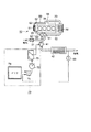
エンジンシステム10は、ディーゼルエンジン20を備えている。ディーゼルエンジン20の入口側には吸気配管30が接続され、出口側には排気配管40が接続されている。さらにディーゼルエンジン20の出口側と吸気配管30とは、排ガス(EGRガス)を吸気配管30に還流するEGR配管50とで接続されている。なお、図1中60は過給機、70はHC供給手段における制御部である。
The
吸気配管30には、吸気側からエアフローセンサ31、過給機60のコンプレッサ61と、インタークーラ32と、吸気スロットル33と、EGR配管50との接続部34とが設けられている。
The
排気配管40には、ディーゼルエンジン20側から、過給機60のタービン62と、NOx吸蔵触媒42と、このNOx吸蔵触媒42の温度を検出する触媒温度センサ43とが設けられている。NOx吸蔵触媒42の排気上流にはHC供給手段としての排気軽油添加インジェクタ41を備えている。
The
NOx吸蔵触媒42は排ガス中の酸素量が多いリーン状態の時に、排気配管40に流入する排ガス中のNOxを吸蔵し、かつ、排ガス中の燃料成分を増加させたリッチ状態(空燃比が理論空燃比以下)のときに吸蔵したNOxを再生処理する。
The
EGR配管50には、排気配管40側から排気ガスを冷却するEGRクーラ51と、排ガスの流量を調節するEGRバルブ52とが設けられている。
The EGR
HC供給制御部70は、予め定められた制御条件にしたがってHC供給のON/OFFを行う供給判定部71と、一定時間をカウントするタイマ72と、このタイマ72の出力が接続され排気軽油添加インジェクタ41への通電を行う通電部73と、閾値マップM1,M2を記憶したメモリ74とを備えている。供給判定部71の制御入力には、触媒温度測定センサ43の計測値と、メモリ74が接続されている。制御出力には、タイマ72を介して通電部73が接続されている。
The HC
閾値マップM1は、昇温開始から最初にSパージ目標温度に到達するまでの運転条件、HC供給量を元にした理想的な昇温速度のマップである。また、閾値マップM2は、一旦、Sパージ目標温度に到達した後の運転条件、HC供給量を元にした理想的な触媒温度のマップである。 The threshold map M1 is an ideal temperature increase rate map based on the operating conditions and the HC supply amount from the start of temperature increase until the S purge target temperature is first reached. The threshold map M2 is an ideal catalyst temperature map based on the operating conditions and the HC supply amount once the S purge target temperature has been reached.
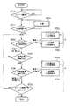
このように構成されたエンジンシステム10では、次のような動作でSパージ運転を行う。図2はSパージ運転のフローを示す説明図である。
In the
すなわち、エンジン運転中に、Sパージの要求の有無が判断され(ST10)、要求があればST11に進む。触媒活性温度以上か否かが判断され(ST11)、触媒活性温度以上であればST20に進む。触媒活性温度未満であれば、ポスト噴射等のディーゼルエンジン20側の制御により昇温させる(ST12)。
That is, during engine operation, it is determined whether or not there is a request for S purge (ST10), and if there is a request, the process proceeds to ST11. It is determined whether the temperature is equal to or higher than the catalyst activation temperature (ST11). If the temperature is equal to or higher than the catalyst activation temperature, the process proceeds to ST20. If the temperature is lower than the catalyst activation temperature, the temperature is raised by control on the
ST20では、閾値マップM1に基づいて触媒温度の上昇速度が判定される。上昇速度が所定値以上の場合にはHC被毒(吸着)現象が発生していないと判断し、ST21に進む。上昇速度が所定値以下の場合にはST22に進む。 In ST20, the rate of increase of the catalyst temperature is determined based on the threshold map M1. If the ascending speed is equal to or higher than the predetermined value, it is determined that the HC poisoning (adsorption) phenomenon has not occurred, and the process proceeds to ST21. If the ascending speed is equal to or lower than the predetermined value, the process proceeds to ST22.
ST21では、触媒温度が所定のSパージ目標温度(例えば600℃)に到達したか否かが判断され、Sパージ目標温度に到達した場合には、ST30に進み、到達していなければST20に戻る。ST22では、HC被毒現象が生じていると判断されることから、通電部73における排気軽油添加インジェクタ41への通電を停止し、一定時間HC供給が中止される。タイマ72によって一定時間経過が計測されると、通電部73により通電HC供給が再開され(ST23)、ST20に戻る。
In ST21, it is determined whether or not the catalyst temperature has reached a predetermined S purge target temperature (eg, 600 ° C.). If the catalyst temperature has reached the S purge target temperature, the process proceeds to ST30, and if not, the process returns to ST20. . In ST22, since it is determined that an HC poisoning phenomenon has occurred, the energization to the exhaust gas
ST30では、閾値マップM2に基づいて触媒温度が触媒温度下限値以上であるか否かが判定され、触媒温度下限値以上であればST31に進む。触媒温度が下限値未満であればST32に進む。 In ST30, it is determined whether or not the catalyst temperature is equal to or higher than the catalyst temperature lower limit value based on the threshold map M2, and if it is equal to or higher than the catalyst temperature lower limit value, the process proceeds to ST31. If the catalyst temperature is less than the lower limit, the process proceeds to ST32.
ST31では、Sパージ運転時間がカウントされ、目標Sパージ時間以上であれば終了し、目標Sパージ時間未満であればST30に戻る。ST32では、一定時間HC供給が中止され、一定時間経過にHC供給が再開され(ST33)、ST30に戻る。 In ST31, the S purge operation time is counted. If it is equal to or longer than the target S purge time, the process ends. If it is less than the target S purge time, the process returns to ST30. In ST32, the HC supply is stopped for a certain time, the HC supply is resumed after a certain time (ST33), and the process returns to ST30.
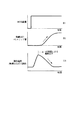
図3のグラフG1〜G3は上述したようなフローでSパージ運転を行った場合におけるHC供給量、触媒出口HCスリップ量、触媒温度の時間変化を示す図である。 Graphs G1 to G3 in FIG. 3 are diagrams showing temporal changes in the HC supply amount, the catalyst outlet HC slip amount, and the catalyst temperature when the S purge operation is performed in the flow as described above.
Sパージ運転が開始された直後の区間A(ST20〜ST23に相当)では、HC供給量に対する触媒温度が一定以上の割合で上昇しており、HC供給は停止せずに、所定の温度に到達する。 In the section A (corresponding to ST20 to ST23) immediately after the start of the S purge operation, the catalyst temperature with respect to the HC supply amount rises at a certain rate, and the HC supply reaches a predetermined temperature without stopping. To do.
触媒温度に到達した後の区間B(ST30〜ST33に相当)では、触媒温度が目標温度よりも下がると、一定時間(区間C)、HC供給が停止される。この間に触媒に酸素が供給されHCが触媒により処理されることにより、触媒温度が再び上昇する。このような動作を繰り返しながら、Sパージの運転時間が予め設定された時間を超えた時点で、Sパージ運転が終了する。 In the section B (corresponding to ST30 to ST33) after reaching the catalyst temperature, the supply of HC is stopped for a certain time (section C) when the catalyst temperature falls below the target temperature. During this time, oxygen is supplied to the catalyst and HC is treated by the catalyst, whereby the catalyst temperature rises again. While repeating this operation, the S purge operation ends when the S purge operation time exceeds a preset time.
上述したように、本実施の形態に係るエンジンシステム10においては、HC供給をする際に所定のタイミングでHC供給を一時停止するようにしているので、HC被毒に伴う温度上昇不良を防止することができ、触媒に付着した硫黄分除去のためのSパージ運転を正常に行うことができる。また、Sパージ運転開始時には昇温開始から最初にSパージ目標温度に到達するまでの運転条件、HC供給量を元にした理想的な昇温速度のマップに基づいているため、HC供給の可否を適切に判定できる。さらに、一旦、Sパージ目標温度に到達した後は、Sパージ運転を行うための触媒温度よりも低い温度の場合にはHC供給を停止し、HCスリップ現象に伴うHC被毒の発生を防止することで、触媒温度の低下を防止することができる。
As described above, in the
なお、本発明は前記実施の形態に限定されるものではない。上述した例では、触媒が劣化してHCの処理効率が低い場合であっても、同様にしてHCスリップ現象を回避し、触媒をSパージ運転のための温度に維持することが可能となる。また、排気通路にディーゼルパティキュレートフィルタを備えた場合におけるフィルタの強制再生時の昇温にも適用可能である。 The present invention is not limited to the above embodiment. In the above-described example, even when the catalyst is deteriorated and the HC treatment efficiency is low, the HC slip phenomenon can be similarly avoided and the catalyst can be maintained at the temperature for the S purge operation. Further, the present invention can also be applied to a temperature increase during forced regeneration of a filter when a diesel particulate filter is provided in the exhaust passage.
く、本発明の要旨を逸脱しない範囲で種々変形実施可能であるのは勿論である。 Of course, various modifications can be made without departing from the scope of the present invention.
10…エンジンシステム、20…ディーゼルエンジン、30…吸気配管、40…排気配管、41…排気軽油添加インジェクタ、42…NOx吸蔵触媒、43…触媒温度測定センサ、50…EGR配管、52…EGRバルブ、60…過給機、70…制御部、71…供給判定部、72…タイマ、73…通電部、74…メモリ。
DESCRIPTION OF
Claims (3)
前記排気通路内にHCを含む還元剤成分を供給する還元剤供給手段と、
前記触媒の温度を検出する触媒温度センサとを備え、
前記還元剤供給手段は、前記Sパージ運転時に還元剤を供給するとともに、所定のタイミングで還元剤供給を所定時間だけ休止することを特徴とするエンジンシステム。 Provided in the exhaust passage of the engine, occludes NOx in the exhaust gas flowing into the exhaust passage, and is regenerated when the air-fuel ratio of the exhaust gas is less than the stoichiometric air-fuel ratio and the reducing agent component increases, A catalyst in which the sulfur component adsorbed during the S purge operation in which the reducing agent component in the exhaust gas is increased and the temperature is raised to a predetermined temperature and the air-fuel ratio is equal to or lower than the theoretical air-fuel ratio is removed;
Reducing agent supply means for supplying a reducing agent component containing HC into the exhaust passage;
A catalyst temperature sensor for detecting the temperature of the catalyst,
The engine system characterized in that the reducing agent supply means supplies the reducing agent during the S purge operation and suspends the reducing agent supply for a predetermined time at a predetermined timing.
Priority Applications (1)
| Application Number | Priority Date | Filing Date | Title |
|---|---|---|---|
| JP2004106452A JP2005291073A (en) | 2004-03-31 | 2004-03-31 | Engine system |
Applications Claiming Priority (1)
| Application Number | Priority Date | Filing Date | Title |
|---|---|---|---|
| JP2004106452A JP2005291073A (en) | 2004-03-31 | 2004-03-31 | Engine system |
Publications (1)
| Publication Number | Publication Date |
|---|---|
| JP2005291073A true JP2005291073A (en) | 2005-10-20 |
Family
ID=35324294
Family Applications (1)
| Application Number | Title | Priority Date | Filing Date |
|---|---|---|---|
| JP2004106452A Pending JP2005291073A (en) | 2004-03-31 | 2004-03-31 | Engine system |
Country Status (1)
| Country | Link |
|---|---|
| JP (1) | JP2005291073A (en) |
-
2004
- 2004-03-31 JP JP2004106452A patent/JP2005291073A/en active Pending
Similar Documents
| Publication | Publication Date | Title |
|---|---|---|
| CN1981915B (en) | Exhaust gas purification device | |
| JP6135198B2 (en) | Control method of exhaust gas aftertreatment device | |
| US7716918B2 (en) | Method of exhaust gas purification and exhaust gas purification system | |
| JP4241032B2 (en) | Sulfur poisoning release control device for diesel engine catalyst | |
| USRE48658E1 (en) | Exhaust gas purification apparatus for an internal combustion engine | |
| JP4720054B2 (en) | Exhaust gas purification device for internal combustion engine | |
| FR2861426A1 (en) | PROCESS FOR RECOVERING A CATALYST | |
| US9051859B2 (en) | Exhaust gas purification device and control method for exhaust gas purification device | |
| CN100449128C (en) | Exhaust purification device and exhaust purification method for internal combustion engine | |
| KR100797503B1 (en) | Exhaust purifier of internal combustion engine | |
| JP3649130B2 (en) | Exhaust gas purification device for internal combustion engine | |
| JP5293279B2 (en) | Exhaust pipe direct fuel injection system and exhaust gas purification system | |
| JP2006291834A (en) | Exhaust purification catalyst thermal degradation state detection device | |
| JP2016151183A (en) | Exhaust emission control system for internal combustion engine, internal combustion engine and exhaust emission control method | |
| JP4291650B2 (en) | Exhaust purification equipment | |
| JP2005155500A (en) | Exhaust gas purification device for internal combustion engine | |
| JP4357241B2 (en) | Exhaust purification equipment | |
| JP4613787B2 (en) | Exhaust gas purification device for internal combustion engine | |
| JP2005291073A (en) | Engine system | |
| JP4692376B2 (en) | Exhaust gas purification device for internal combustion engine | |
| JP4263642B2 (en) | Exhaust gas purification device for internal combustion engine | |
| JP4325723B2 (en) | Exhaust gas purification device for internal combustion engine | |
| JP2007077875A (en) | Exhaust gas purification system for internal combustion engine | |
| JP5151959B2 (en) | Exhaust gas purification system and exhaust gas purification method | |
| JP2002364439A (en) | Exhaust gas purification device for internal combustion engine |
Legal Events
| Date | Code | Title | Description |
|---|---|---|---|
| A621 | Written request for application examination |
Effective date: 20070112 Free format text: JAPANESE INTERMEDIATE CODE: A621 |
|
| A977 | Report on retrieval |
Free format text: JAPANESE INTERMEDIATE CODE: A971007 Effective date: 20090831 |
|
| A131 | Notification of reasons for refusal |
Free format text: JAPANESE INTERMEDIATE CODE: A131 Effective date: 20090901 |
|
| A02 | Decision of refusal |
Effective date: 20100105 Free format text: JAPANESE INTERMEDIATE CODE: A02 |