JP2005291314A - Vibration control device - Google Patents
Vibration control device Download PDFInfo
- Publication number
- JP2005291314A JP2005291314A JP2004105693A JP2004105693A JP2005291314A JP 2005291314 A JP2005291314 A JP 2005291314A JP 2004105693 A JP2004105693 A JP 2004105693A JP 2004105693 A JP2004105693 A JP 2004105693A JP 2005291314 A JP2005291314 A JP 2005291314A
- Authority
- JP
- Japan
- Prior art keywords
- vibration
- damper
- damping device
- main
- vibration damping
- Prior art date
- Legal status (The legal status is an assumption and is not a legal conclusion. Google has not performed a legal analysis and makes no representation as to the accuracy of the status listed.)
- Pending
Links
- 238000013016 damping Methods 0.000 claims abstract description 136
- 239000012530 fluid Substances 0.000 claims abstract description 28
- 230000008602 contraction Effects 0.000 claims abstract description 20
- 230000005284 excitation Effects 0.000 claims description 37
- 230000001133 acceleration Effects 0.000 claims description 22
- 230000002238 attenuated effect Effects 0.000 claims description 4
- 230000000694 effects Effects 0.000 abstract description 13
- 238000010586 diagram Methods 0.000 description 5
- 239000007788 liquid Substances 0.000 description 3
- 230000010354 integration Effects 0.000 description 2
- 230000001629 suppression Effects 0.000 description 2
- 230000005674 electromagnetic induction Effects 0.000 description 1
- XLYOFNOQVPJJNP-UHFFFAOYSA-N water Substances O XLYOFNOQVPJJNP-UHFFFAOYSA-N 0.000 description 1
Images
Landscapes
- Vibration Prevention Devices (AREA)
Abstract
Description
本発明は、構造物上に設置され、この構造物の振動を減衰させて制振するために用いられる制振装置に関するものである。 The present invention relates to a vibration damping device that is installed on a structure and is used to damp and dampen the vibration of the structure.
このような制振装置の一例として、例えば特許文献1に開示されているようなものが知られている。
この制振装置は、所定の質量を有する制振体が構造物上でバネによって支えられて移動可能に設けられて構成されたダンパーを備えており、制振体が振動することによって構造物の振動を減衰させるものである。また、この制振装置は、制振体に対して電磁誘導によって加振力を作用させるための加振手段を備えており、構造物が振動したときに、上記制振体が受動的(パッシブ)に振動して構造物の振動を減衰させるのではなく、上記制振体を加振手段によって能動的(アクティブ)に振動させて構造物の振動を減衰させるようになっている。
This vibration damping device includes a damper that is configured such that a vibration damping body having a predetermined mass is supported on a structure by a spring so as to be movable. It attenuates vibrations. Further, the vibration damping device includes a vibration means for applying a vibration force to the vibration damping body by electromagnetic induction, and the vibration damping body is passive (passive) when the structure vibrates. ) To dampen the vibration of the structure, but the vibration damping body is vibrated actively by the vibrating means to dampen the vibration of the structure.
しかしながら、上記のような制振装置では、1つのダンパーのみによって構造物の振動を直接減衰させるようにしたものであるため、たとえ加振手段を用いてアクティブに構造物の振動を減衰させるようにしたとしても、十分な制振効果を得ることができないのが現状であった。
本発明は、上記課題に鑑みてなされたもので、十分な制振効果を得ることができる制振装置を提供することを目的としている。
However, in the vibration damping device as described above, the vibration of the structure is directly damped by only one damper. Therefore, even if the vibration of the structure is actively damped by using the vibration means. Even so, the current situation is that a sufficient damping effect cannot be obtained.
The present invention has been made in view of the above problems, and an object thereof is to provide a vibration damping device capable of obtaining a sufficient vibration damping effect.
上記の課題を解決して、このような目的を達成するために、本発明による制振装置は、構造物上に設置され、この構造物の振動を減衰させる制振装置であって、前記構造物の振動を減衰させる主ダンパーと、前記主ダンパーの振動を減衰させる副ダンパーとを備えていることを特徴とするものである。 In order to solve the above problems and achieve such an object, a vibration damping device according to the present invention is a vibration damping device that is installed on a structure and damps the vibration of the structure. The apparatus includes a main damper that attenuates vibration of an object and a sub-damper that attenuates vibration of the main damper.
本発明の制振装置によれば、構造物が振動したときに、その振動を減衰させるための主ダンパーを備えているだけではなく、この主ダンパーの振動を減衰させるための副ダンパーを備えていることから、構造物の振動が効果的に抑制され、十分な制振効果を得ることが可能となる。
なお、本発明の制振装置は、このような主ダンパーと副ダンパーとを備えていることによって、受動的に構造物の振動を減衰させるパッシブタイプのものとされていたとしても十分な制振効果を得ることが可能ではあるが、本発明の制振装置が、前記主ダンパー及び前記副ダンパーのうちの少なくとも一方に対して加振力を入力する加振手段を備えていて、能動的に構造物の振動を減衰させるアクティブタイプのものとされていることが好ましい。
このような構成とすることによって、制振装置の小型化を図りつつも、小さい加振力でより大きな制振効果を得ることが可能となり、とくに、加振手段が副ダンパーに対して加振力を入力するようになっていれば、幅広い周波数の振動に対する追従性が高められ、さらなる制振効果の向上を図ることができる。
According to the vibration damping device of the present invention, when the structure vibrates, not only has the main damper for damping the vibration, but also has the sub-damper for damping the vibration of the main damper. Therefore, the vibration of the structure is effectively suppressed, and a sufficient damping effect can be obtained.
Note that the vibration damping device of the present invention is provided with such a main damper and a sub damper, so that even if it is a passive type that passively attenuates the vibration of the structure, the vibration damping device is sufficient. Although it is possible to obtain the effect, the vibration damping device of the present invention includes a vibration means for inputting a vibration force to at least one of the main damper and the sub damper, and actively It is preferable to be an active type that attenuates the vibration of the structure.
By adopting such a configuration, it is possible to obtain a greater vibration suppression effect with a small vibration force while reducing the size of the vibration damping device. If force is input, the followability to vibrations of a wide range of frequencies can be improved, and the vibration damping effect can be further improved.
本発明の制振装置の具体的な一例として、前記主ダンパーは、流体が前記構造物上に設置されたタンクに空気室を形成するように収容されて構成されており、前記流体が振動することによって前記構造物の振動を減衰させ、前記副ダンパーは、容積変化可能な伸縮部が前記タンクに接続されて構成されており、前記伸縮部が容積変化することによって前記流体の振動を減衰させるようにした流体式のものが挙げられる。
このような構成とすることにより、後述する機械式の制振装置と比較したときに、制振体を構造物上で移動可能とするためのレールなどの摺動部が必要とならないため、摩耗によって疲労しやすい箇所がなくなり、装置寿命の延長を図ることができる。
As a specific example of the vibration damping device of the present invention, the main damper is configured such that a fluid is accommodated so as to form an air chamber in a tank installed on the structure, and the fluid vibrates. The sub-damper is configured such that a volume-variable expansion / contraction part is connected to the tank, and the volume of the expansion / contraction part changes the volume of the fluid to dampen the vibration of the fluid. Examples of such fluid type are mentioned.
By adopting such a configuration, when compared with a mechanical vibration control device to be described later, a sliding part such as a rail for enabling the vibration control body to move on the structure is not required. As a result, there is no place where fatigue tends to occur, and the life of the apparatus can be extended.
また、前記伸縮部は、前記タンクに着脱可能に接続されていることが好ましい。
このような構成とすることにより、容積変化を繰り返すことで伸縮部に疲労が蓄積してしまった場合であっても、この疲労した伸縮部をタンクから取り外して新たな伸縮部をタンクに取り付けるだけで済み、制振装置全体を交換するようなことがない。
Moreover, it is preferable that the said expansion-contraction part is connected to the said tank so that attachment or detachment is possible.
By adopting such a configuration, even if fatigue accumulates in the stretchable part due to repeated volume changes, just remove this fatigued stretchable part from the tank and attach a new stretchable part to the tank No need to replace the entire damping device.
ここで、このような流体式の制振装置が、前記主ダンパー及び前記副ダンパーのうちの少なくとも一方に対して加振力を入力する加振手段を備えている場合、この加振手段が、構造物の振動を効果的に減衰させるための加振力を入力するようにするための具体的な構成例としては、以下に示すようなものが挙げられる。
・本発明の制振装置が、前記構造物が振動するときの加速度を検出する加速度計と、前記流体が振動するときの圧力を検出する圧力計と、前記加速度計で検出された前記加速度と前記圧力計で検出された前記圧力とに基づいて前記加振力を演算し、この演算した加振力を前記加振手段が入力するように制御する制御器とを備える。
Here, when such a fluid type vibration damping device includes a vibration means for inputting a vibration force to at least one of the main damper and the sub damper, the vibration means includes: Specific examples of the configuration for inputting the excitation force for effectively attenuating the vibration of the structure include the following.
The vibration damping device of the present invention includes an accelerometer that detects an acceleration when the structure vibrates, a pressure gauge that detects a pressure when the fluid vibrates, and the acceleration detected by the accelerometer. A controller that calculates the excitation force based on the pressure detected by the pressure gauge and controls the excitation unit to input the calculated excitation force.
また、本発明の制振装置の他の具体的な一例として、前記主ダンパーは、主制振体が前記構造物上で主弾性体によって支えられて移動可能に設けられて構成されており、前記主制振体が振動することによって前記構造物の振動を減衰させ、前記副ダンパーは、副制振体が前記主制振体上で副弾性体によって支えられて移動可能に設けられて構成されており、前記副制振体が振動することによって前記主制振体の振動を減衰させるようにした機械式のものが挙げられる。 Further, as another specific example of the vibration damping device of the present invention, the main damper is configured such that the main vibration damping body is supported by the main elastic body on the structure and is movable. The main vibration damping body attenuates the vibration of the structure, and the secondary damper is configured such that the secondary vibration damping body is supported on the main vibration damping body by the secondary elastic body and is movable. There is a mechanical type in which the vibration of the main vibration damping body is attenuated by the vibration of the auxiliary vibration damping body.
ここで、このような機械式の制振装置が、前記主ダンパー及び前記副ダンパーのうちの少なくとも一方に対して加振力を入力する加振手段を備えている場合、この加振手段が、構造物の振動を効果的に減衰させるための加振力を入力するようにするための具体的な構成例としては、以下に示すようなものが挙げられる。
・本発明の制振装置が、前記構造物が振動するときの加速度を検出する加速度計と、前記主制振体が振動するときの速度を検出する速度計と、前記加速度計で検出された前記加速度と前記速度計で検出された前記速度とに基づいて前記加振力を演算し、この演算した加振力を前記加振手段が入力するように制御する制御器とを備える。
Here, in the case where such a mechanical vibration damping device includes a vibration unit that inputs a vibration force to at least one of the main damper and the sub damper, the vibration unit includes: Specific examples of the configuration for inputting the excitation force for effectively attenuating the vibration of the structure include the following.
The vibration damping device of the present invention is detected by an accelerometer that detects an acceleration when the structure vibrates, a speedometer that detects a speed when the main vibration damping body vibrates, and the accelerometer. A controller that calculates the excitation force based on the acceleration and the velocity detected by the speedometer, and controls the excitation unit to input the calculated excitation force.
まず、本発明の第1実施形態を添付した図1及び図2を参照しながら説明する。
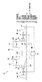
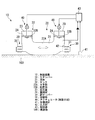
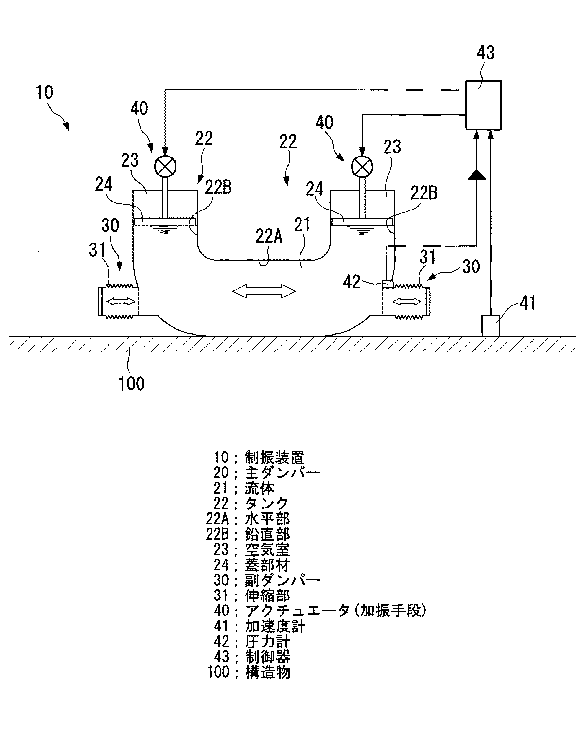
本第1実施形態による制振装置10は、図1に示すように、主ダンパー20と副ダンパー30とを備えたものであり、例えば船舶における居住区の屋上である構造部100上に設置されることによって、この構造物100の振動を減衰させて制振するものである。
First, a first embodiment of the present invention will be described with reference to FIGS.
As shown in FIG. 1, the
主ダンパー20は、例えば水などの液体である流体21が、構造物100上に設置されたU字管状のタンク22に収容されて構成されている。タンク22は、水平方向に延在させられた水平部22Aとこの水平部22Aの両端に一体に連結された鉛直部22B,22BとからなるU字管状とされたものであり、流体21が水平部22A及び鉛直部22B,22Bの下方側部分に満たされていることにより、各鉛直部22B,22Bの上方側部分にそれぞれ空気室23,23が形成されている。なお、これら空気室23,23は、構造物100の振動数に応じて、大気に開放された状態、密閉された状態、加圧された状態のいずれかに維持される。
このような主ダンパー20は、構造物100が振動したときに、流体21がタンク22の水平部22Aを水平方向に振動することによって、構造物100の振動を減衰させるようになっている。
The
The
副ダンパー30は、容積変化可能な管状をなす一対の伸縮部31,31が、タンク22における水平部22Aの両端(水平部22Aと各鉛直部22B,22Bとの連結部分)に接続されて構成されている。伸縮部31,31は、水平方向に延在させられた例えば蛇腹構造を有する管状とされたものであり、タンク22の内部に連通させられていることにより、各伸縮部31,31にも流体21が収容されている。なお、これら伸縮部31,31は、フランジ構造(図1における破線部分)によって、タンク22に着脱可能に接続されている。
このような副ダンパー30は、タンク22に収容された流体21が振動したときに、同じくこの流体21が収容された状態の伸縮部31,31が容積変化することによって、流体21の振動を減衰させるようになっている。
The
When the
また、本第1実施形態では、副ダンパー30に対して加振力を入力するための加振手段として、後述する制御器43によって制御される一対のアクチュエータ40,40が設けられている。アクチュエータ40,40は、副ダンパー30を構成する一対の伸縮部31,31の端面に対して加振力を作用させ、かつ、この加振力の反力を構造物100(構造物100に固定設置された支柱101,101)に対して作用させるように配置されている。
このような一対のアクチュエータ40,40は、制御器43によって演算された加振力を副ダンパー30の伸縮部31,31に対して作用させ、これら伸縮部31,31を容積変化させることにより、アクティブに流体21を振動させて構造物100の振動を減衰させるようになっている。
In the first embodiment, a pair of
Such a pair of
さらに、本第1実施形態では、構造物100が振動するときの加速度を検出するための加速度計41が構造物100上に設置されるように設けられ、流体21が振動するときの圧力を検出するための圧力計42がタンク22内における一方の伸縮部31の接続部に設置されるように設けられており、これら加速度計41及び圧力計42は、制御器43に接続されている。とくに、圧力計42は、積分回路を介して制御器43に接続されている。
Further, in the first embodiment, an
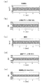
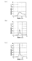
制御器43は、構造物100が振動したときに(例えば、7Hz(構造物100の固有振動数)、1tonの振動が起振力として構造物100に印加されたときに)、加速度計41で検出された構造物100の加速度aと圧力計42で検出された流体21の圧力pとに基づき、上記加速度a(図3(a)参照)にゲインKaを掛けて得られた状態量Ka*a(図3(b)参照)と、上記圧力pから求められる流体21の速度v(図3(c)参照)を積分してからゲインKvを掛けて得られた状態量Kv*v(図3(d)参照)とを加算した状態量Ka*a+Kv*v(図3(e)参照)、つまり、加振手段としてのアクチュエータ40,40が副ダンパー30の伸縮部31,31に対して作用させるべき加振力を演算する。
When the
そして、制御器43は、演算した加振力を加振手段である一対のアクチュエータ40,40が副ダンパー30の一対の伸縮部31,31に対して作用させるように、各アクチュエータ40,40を制御する。
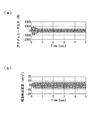
その結果、一対のアクチュエータ40,40が、図4(a)に示すような出力とされる加振力を、副ダンパー30の一対の伸縮部31,31に対して作用させて、これら一対の伸縮部31,31をアクティブに容積変化(振動)させることにより、構造物100の振動を減衰させて制振するので、この構造物100が振動するときの加速度が図4(b)に示すようになる。
Then, the
As a result, the pair of
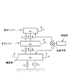
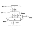
ここで、上記のような構成とされた制振装置10は、図2のようなモデル図として示され、その運動方程式は、以下の式(1)において、F1=f−u、F2=0、F3=u、となる。
以上説明したような本第1実施形態の制振装置10では、構造物100が振動したときに、その振動を減衰させるための主ダンパー20を備えているだけではなく、この主ダンパー20の振動を減衰させるための副ダンパー30を備えていることから、構造物100の振動が効果的に抑制され、十分な制振効果を得ることが可能となっている。
The
また、このような主ダンパー20と副ダンパー30とを備えた本第1実施形態による制振装置10が、副ダンパー30に対して加振力を入力するための加振手段を備えていて、能動的に構造物100の振動を減衰させるアクティブタイプのものとされていることから、制振装置10の小型化を図りつつも、小さい加振力で従来より大きな制振効果を得ることができるのに加え、構造物100に生じる振動の幅広い周波数に対する追従性を高めることができる。
Further, the
ここで、図5(a)に、本第1実施形態の制振装置10を用いてアクティブに構造物100を制振したときの構造物100の振動の加速度を示し、図5(b)に、本第1実施形態の制振装置10を用いてパッシブに構造物100を制振したとき(加振手段を使用しないとき)の構造物100の振動の加速度を示し、図5(c)に、制振装置10を用いないときの構造物100の振動の加速度を示す。
図5に示されるように、本第1実施形態の制振装置10は、構造物100の振動をパッシブに減衰させたときでも、十分な制振効果を得ることができ、とくに、構造物100の振動をアクティブに減衰させたときには、とくに優れた制振効果を得ることができているのが分かる。
Here, FIG. 5A shows acceleration of vibration of the
As shown in FIG. 5, the
また、本第1実施形態による制振装置10は、例えば船舶における居住区の屋上部である構造部100上に設置されて用いられることから、制振対象となる構造物100の振動数が5〜10Hzとなって例えば地震の場合(1〜2Hz)と比べて高いため、制振装置10の小型化につながっている。
Further, since the
さらに、本第1実施形態による制振装置10は、流体21を用いて構造物100の振動を減衰させる流体式のものとされていることから、機械式の制振装置のように、制振体を構造物100上で移動可能にするレールなどの摺動部が存在せず、摩耗によって疲労しやすい部分がないので、装置寿命の延長を図ることができる。
このとき、制振装置10の副ダンパー30を構成している伸縮部31,31が、タンク22に対して着脱可能とされていることから、容積変化を繰り返すことで伸縮部31,31に疲労が蓄積した場合であっても、これらの疲労した伸縮部31,31を新たなものに取り替えるだけで済み、制振装置10全体を交換するような必要がない。
Furthermore, since the
At this time, since the expansion /
加えて、本第1実施形態による制振装置10は、構造物100が振動するときの加速度を検出する加速度計41と、流体21が振動するときの圧力を検出する圧力計42と、これら加速度計41及び圧力計42で検出された2つの情報に基づいて加振手段であるアクチュエータ40,40が副ダンパー30に入力するべき加振力を演算する制御器40とを備えていることから、構造物100のアクティブな制振をより確実なものとすることができる。
In addition, the
次に、本発明の第2実施形態を添付した図6及び図7を参照しながら説明するが、上述した第1実施形態と同様の部分には同一の符号を用いてその説明を省略する。
本第2実施形態による制振装置10は、第1実施形態と同様の構成をなすものであるが、副ダンパー30ではなく主ダンパー20に対して加振力を入力するための加振手段として、制御器43によって制御される一対のアクチュエータ40,40が設けられている。アクチュエータ40,40は、タンク22の各鉛直部22B,22B内に存在する流体21の液面に載置された蓋部材24,24に対して加振力を作用させ、かつ、この加振力の反力を構造物100に対して作用させる(図示略)ように配置されている。
Next, a second embodiment of the present invention will be described with reference to FIG. 6 and FIG. 7 attached, but the same reference numerals are used for the same parts as in the first embodiment described above, and the description thereof is omitted.
The
このような一対のアクチュエータ40,40は、制御器43によって演算された加振力を主ダンパー20の蓋部材24,24に対して作用させることにより、これら蓋部材24,24が液面に載置された状態となっている流体21をアクティブに振動させて構造物100の振動を減衰させるようになっている。
ここで、上記のような構成とされた制振装置10は、図7のようなモデル図として示され、その運動方程式は、上記の式(1)において、F1=f−u、F2=u、F3=0、となる。
この第2実施形態による制振装置10では、上述した第1実施形態と類似の構成を採用した部分については同様の効果を得ることが可能となっている。
Such a pair of
Here, the
In the
次に、本発明の第3実施形態を添付した図8を参照しながら説明するが、上述した第1〜2実施形態と同様の部分には同一の符号を用いてその説明を省略する。
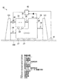
本第3実施形態による制振装置10において、主ダンパー20は、所定の質量を有する剛体である主制振体26が、例えばレールなどの主摺動部27を介して構造物100上に載置されるとともに、この主制振体26の両端部のそれぞれが主弾性体としての主バネ28,28によって支えられることにより、水平方向に移動(振動)可能に設けられて構成されている。主弾性体としての一対の主バネ28,28は、それらの片側端部が主制振体26に対して接続されるとともに、残りの片側端部が構造物100(構造物100に固定設置された支柱101,101)に対して接続されることにより、主制振体26を支えている。
このような主ダンパー20は、構造物100が振動したときに、主制振体26が構造物100上で水平方向に振動することによって、構造物100の振動を減衰させるようになっている。
Next, a third embodiment of the present invention will be described with reference to FIG. 8 attached, but the same parts as those in the first and second embodiments described above will be denoted by the same reference numerals and the description thereof will be omitted.
In the
The
副ダンパー30は、主制振体26よりも小さい所定の質量を有する剛体である副制振体33が、例えばレールなどの副摺動部34を介して主制振体26上に載置されるとともに、この副制振体33の片側端部が副弾性体としての副バネ35によって支えられることにより、水平方向に移動(振動)可能に設けられて構成されている。副弾性体としての副バネ28は、その片側端部が副制振体33に対して接続されるとともに、残りの片側端部が構造物100(構造物100に固定設置された支柱101)に対して接続されることにより、副制振体33を支えている。
このような副ダンパー30は、主制振体26が振動したときに、副制振体33が主制振体26上で水平方向に振動することによって、主制振体26の振動を減衰させるようになっている。
In the
Such a
また、本第3実施形態では、副ダンパー30に対して加振力を入力するための加振手段として、後述する制御器43によって制御されるアクチュエータ40が設けられている。アクチュエータ40は、副ダンパー30を構成する副制振体33において副バネ35が接続されていない片側端部に対して加振力を作用させ、かつ、この加振力の反力を構造物100(構造物100に固定設置された支柱101)に対して作用させるように配置されている。
このようなアクチュエータ40は、制御器43によって演算された加振力を副ダンパー30の副制振体33に対して作用させ、この副制振体33を振動させることにより、アクティブに副制振体33を振動させて構造物100の振動を減衰させるようになっている。
In the third embodiment, an
Such an
さらに、本第3実施形態では、構造物100が振動するときの加速度を検出するための加速度計41が構造物100上に設置されるように設けられ、主制振体26が振動するときの速度を検出するための速度計44が主制振体26上に設置されるように設けられており、これら加速度計41及び速度計44は、制御器43に接続されている。とくに、速度計44は、積分回路を介して制御器43に接続されている。
Furthermore, in the third embodiment, an
制御器43は、構造物100が振動したときに、加速度計41で検出された構造物100の加速度と速度計44で検出された主制振体26の速度とに基づき、上記加速度にゲインを掛けて得られた状態量と、上記速度を積分してからゲインを掛けて得られた状態量とを加算した状態量、つまり、加振手段としてのアクチュエータ40が副ダンパー30の副制振体33に対して作用させるべき加振力を演算する。
When the
そして、制御器43は、演算した加振力を加振手段であるアクチュエータ40が副ダンパー30の副制振体33に対して作用させるように、アクチュエータ40を制御する。
その結果、アクチュエータ40が、所定の加振力を副ダンパー30の副制振体33に対して作用させて、この副制振体33をアクティブに振動させることにより、構造物100の振動を減衰させて制振する。
Then, the
As a result, the
ここで、上記のような構成とされた制振装置10は、第1実施形態と同じく図2のようなモデル図として示され、その運動方程式は、上記の式(1)において、F1=f−u、F2=0、F3=u、となる。
この第3実施形態による制振装置10では、上述した第1〜2実施形態と類似の構成を採用した部分については同様の効果を得ることが可能となっている。
Here, the
In the
次に、本発明の第4実施形態を添付した図9を参照しながら説明するが、上述した第1〜3実施形態と同様の部分には同一の符号を用いてその説明を省略する。
本第4実施形態による制振装置10は、第3実施形態と同様の構成をなすものであるが、副ダンパー30ではなく主ダンパー20に対して加振力を入力するための加振手段として、制御器43によって制御されるアクチュエータ40が設けられている。そのため、主ダンパー20は、主制振体26の片側端部が主弾性体としての主バネ28によって支えられ、副ダンパー30は、副制振体33の両端部のそれぞれが副弾性体としての副バネ35,35によって支えられている。アクチュエータ40は、主ダンパー20を構成する主制振体26において主バネ28が接続されていない片側端部に対して加振力を作用させ、かつ、この加振力の反力を構造物100(構造物100に固定設置された支柱101)に対して作用させるように配置されている。
Next, a fourth embodiment of the present invention will be described with reference to FIG. 9 attached, but the same parts as those in the first to third embodiments described above will be denoted by the same reference numerals and the description thereof will be omitted.
The
このようなアクチュエータ40は、制御器43によって演算された加振力を主ダンパー20の主制振体26に対して作用させ、この主制振体26を振動させることにより、アクティブに主制振体26を振動させて構造物100の振動を減衰させるようになっている。
ここで、上記のような構成とされた制振装置10は、図7のようなモデル図として示され、その運動方程式は、上記の式(1)において、F1=f−u、F2=u、F3=0、となる。
この第4実施形態による制振装置10は、上述した第1〜3実施形態と類似の構成を採用した部分については、同様の効果を得ることが可能となる。
Such an
Here, the
The
なお、上述した各実施形態では、副ダンパー30あるいは主ダンパー20に対して加振力を入力するための加振手段が、この加振力の反力を構造物100に対して入力する(図2、図7)ようになっているが、これに限定されることはなく、例えば、副ダンパー30に対して加振力を入力するとともにその反力を主ダンパー20に対して入力するような加振手段を設けることもできる(この場合、上記の式(1)において、F1=f、F2=−u、F3=u、となる)。
In each of the above-described embodiments, the excitation means for inputting the excitation force to the
10 制振装置
20 主ダンパー
21 流体
22 タンク
23 空気室
26 主制振体
28 主バネ(主弾性体)
30 副ダンパー
31 伸縮部
33 副制振体
35 副バネ(副弾性体)
40 アクチュエータ(加振手段)
41 加速度計
42 圧力計
43 制御器
44 速度計
100 構造物
DESCRIPTION OF
30 Sub-damper 31
40 Actuator (Excitation means)
41
Claims (11)
前記構造物の振動を減衰させる主ダンパーと、
前記主ダンパーの振動を減衰させる副ダンパーとを備えていることを特徴とする制振装置。 A damping device that is installed on a structure and attenuates the vibration of the structure,
A main damper that attenuates vibrations of the structure;
And a sub-damper that attenuates vibrations of the main damper.
前記主ダンパー及び前記副ダンパーのうちの少なくとも一方に対して加振力を入力する加振手段を備えていることを特徴とする制振装置。 The vibration damping device according to claim 1,
A vibration damping device comprising vibration means for inputting a vibration force to at least one of the main damper and the sub damper.
前記主ダンパーは、流体が前記構造物上に設置されたタンクに空気室を形成するように収容されて構成されており、前記流体が振動することによって前記構造物の振動を減衰させることを特徴とする制振装置。 The vibration damping device according to claim 1,
The main damper is configured such that a fluid is accommodated so as to form an air chamber in a tank installed on the structure, and the vibration of the structure is attenuated by the vibration of the fluid. Damping device.
前記副ダンパーは、容積変化可能な伸縮部が前記タンクに接続されて構成されており、前記伸縮部が容積変化することによって前記流体の振動を減衰させることを特徴とする制振装置。 In the vibration damping device according to claim 3,
The sub-damper is configured by connecting an expansion / contraction part whose volume can be changed to the tank, and the vibration of the fluid is attenuated by the volume change of the expansion / contraction part.
前記伸縮部は、前記タンクに着脱可能に接続されていることを特徴とする制振装置。 The vibration damping device according to claim 4,
The expansion / contraction part is detachably connected to the tank.
前記主ダンパー及び前記副ダンパーのうちの少なくとも一方に対して加振力を入力する加振手段を備えていることを特徴とする制振装置。 The vibration damping device according to any one of claims 3 to 5,
A vibration damping device comprising vibration means for inputting a vibration force to at least one of the main damper and the sub damper.
前記構造物が振動するときの加速度を検出する加速度計と、
前記流体が振動するときの圧力を検出する圧力計と、
前記加速度計で検出された前記加速度と前記圧力計で検出された前記圧力とに基づいて前記加振力を演算し、この演算した加振力を前記加振手段が入力するように制御する制御器とを備えていることを特徴とする制振装置。 The vibration damping device according to claim 6,
An accelerometer that detects acceleration when the structure vibrates;
A pressure gauge for detecting a pressure when the fluid vibrates;
Control for calculating the excitation force based on the acceleration detected by the accelerometer and the pressure detected by the pressure gauge, and controlling the excitation means to input the calculated excitation force And a vibration control device.
前記主ダンパーは、主制振体が前記構造物上で主弾性体によって支えられて移動可能に設けられて構成されており、前記主制振体が振動することによって前記構造物の振動を減衰させることを特徴とする制振装置。 The vibration damping device according to claim 1,
The main damper is configured such that a main damping body is supported by a main elastic body on the structure so as to be movable, and the vibration of the structure is attenuated by the vibration of the main damping body. A vibration control device characterized in that
前記副ダンパーは、副制振体が前記主制振体上で副弾性体によって支えられて移動可能に設けられて構成されており、前記副制振体が振動することによって前記主制振体の振動を減衰させることを特徴とする制振装置。 The vibration damping device according to claim 8,
The auxiliary damper is configured such that the auxiliary damping body is supported by the auxiliary elastic body on the main damping body so as to be movable, and the main damping body vibrates when the auxiliary damping body vibrates. Damping device characterized by attenuating vibration of
前記主ダンパー及び前記副ダンパーのうちの少なくとも一方に対して加振力を入力する加振手段を備えていることを特徴とする制振装置。 The vibration damping device according to claim 8 or 9,
A vibration damping device comprising vibration means for inputting a vibration force to at least one of the main damper and the sub damper.
前記構造物が振動するときの加速度を検出する加速度計と、
前記主制振体が振動するときの速度を検出する速度計と、
前記加速度計で検出された前記加速度と前記速度計で検出された前記速度とに基づいて前記加振力を演算し、この演算した加振力を前記加振手段が入力するように制御する制御器とを備えていることを特徴とする制振装置。 The vibration damping device according to claim 10, wherein
An accelerometer that detects acceleration when the structure vibrates;
A speedometer for detecting a speed when the main damping body vibrates;
Control for calculating the excitation force based on the acceleration detected by the accelerometer and the velocity detected by the speedometer, and controlling the excitation means to input the calculated excitation force And a vibration control device.
Priority Applications (1)
| Application Number | Priority Date | Filing Date | Title |
|---|---|---|---|
| JP2004105693A JP2005291314A (en) | 2004-03-31 | 2004-03-31 | Vibration control device |
Applications Claiming Priority (1)
| Application Number | Priority Date | Filing Date | Title |
|---|---|---|---|
| JP2004105693A JP2005291314A (en) | 2004-03-31 | 2004-03-31 | Vibration control device |
Publications (1)
| Publication Number | Publication Date |
|---|---|
| JP2005291314A true JP2005291314A (en) | 2005-10-20 |
Family
ID=35324481
Family Applications (1)
| Application Number | Title | Priority Date | Filing Date |
|---|---|---|---|
| JP2004105693A Pending JP2005291314A (en) | 2004-03-31 | 2004-03-31 | Vibration control device |
Country Status (1)
| Country | Link |
|---|---|
| JP (1) | JP2005291314A (en) |
Cited By (3)
| Publication number | Priority date | Publication date | Assignee | Title |
|---|---|---|---|---|
| JP2015163490A (en) * | 2014-02-28 | 2015-09-10 | 三菱重工業株式会社 | Antimotion device and ship |
| CN113323982A (en) * | 2020-05-10 | 2021-08-31 | 河南牛帕力学工程研究院 | Anti-resonance damping method for structural body |
| CN115262794A (en) * | 2022-08-22 | 2022-11-01 | 中建八局第三建设有限公司 | Multi-point control system for horizontal vibration of building |
-
2004
- 2004-03-31 JP JP2004105693A patent/JP2005291314A/en active Pending
Cited By (4)
| Publication number | Priority date | Publication date | Assignee | Title |
|---|---|---|---|---|
| JP2015163490A (en) * | 2014-02-28 | 2015-09-10 | 三菱重工業株式会社 | Antimotion device and ship |
| KR101827040B1 (en) * | 2014-02-28 | 2018-02-07 | 미츠비시 쥬고교 가부시키가이샤 | Swing motion reducing apparatus and ship |
| CN113323982A (en) * | 2020-05-10 | 2021-08-31 | 河南牛帕力学工程研究院 | Anti-resonance damping method for structural body |
| CN115262794A (en) * | 2022-08-22 | 2022-11-01 | 中建八局第三建设有限公司 | Multi-point control system for horizontal vibration of building |
Similar Documents
| Publication | Publication Date | Title |
|---|---|---|
| JP6308999B2 (en) | Active vibration isolation system | |
| US6874748B2 (en) | Active floor vibration control system | |
| CN105229334B (en) | Mixing vibration shielding system for measuring table | |
| JP6775029B2 (en) | Active inertia damper system and method | |
| KR20130012786A (en) | Tuned mass damper using metal plate spring and vibration isolation base using the tuned mass damper | |
| JP5993658B2 (en) | Vibration testing machine | |
| CN109736362A (en) | Vibration isolation system | |
| JP4855378B2 (en) | Damping device, damping method and damping program | |
| JP2011247314A (en) | Active vibration removing device | |
| JP5005068B2 (en) | Quay crane and control method thereof | |
| JP4897619B2 (en) | Active vibration isolation system with air bearing without hysteresis | |
| JP2013029137A (en) | Damping device | |
| JP2013029136A (en) | Active damping device | |
| JP4706312B2 (en) | Seismic isolation device, seismic isolation system | |
| CN100465473C (en) | Actuator arrangement for active vibration isolation including inertial reference mass | |
| KR20130073645A (en) | High damping vertical dynamic absorber | |
| JP2007205543A (en) | Vibration cancellation device | |
| JP2847225B2 (en) | Anti-resonance type active dynamic vibration absorber | |
| JP2004332847A (en) | Damping device | |
| JP2008281048A (en) | Active vibration removing device | |
| JP2010196839A (en) | Damping device | |
| JP4239362B2 (en) | Active vibration control method | |
| JPS62155347A (en) | Active vibrationproof supporting device | |
| JP4314930B2 (en) | Vibration absorber | |
| RU87483U1 (en) | ADAPTIVE VIBRATOR |
Legal Events
| Date | Code | Title | Description |
|---|---|---|---|
| A621 | Written request for application examination |
Free format text: JAPANESE INTERMEDIATE CODE: A621 Effective date: 20060206 |
|
| A977 | Report on retrieval |
Free format text: JAPANESE INTERMEDIATE CODE: A971007 Effective date: 20080519 |
|
| A131 | Notification of reasons for refusal |
Free format text: JAPANESE INTERMEDIATE CODE: A131 Effective date: 20080624 |
|
| A02 | Decision of refusal |
Free format text: JAPANESE INTERMEDIATE CODE: A02 Effective date: 20081021 |