JP2005291430A - Pipe coupling - Google Patents
Pipe coupling Download PDFInfo
- Publication number
- JP2005291430A JP2005291430A JP2004109761A JP2004109761A JP2005291430A JP 2005291430 A JP2005291430 A JP 2005291430A JP 2004109761 A JP2004109761 A JP 2004109761A JP 2004109761 A JP2004109761 A JP 2004109761A JP 2005291430 A JP2005291430 A JP 2005291430A
- Authority
- JP
- Japan
- Prior art keywords
- hole
- joint
- pipe
- hose
- diameter
- Prior art date
- Legal status (The legal status is an assumption and is not a legal conclusion. Google has not performed a legal analysis and makes no representation as to the accuracy of the status listed.)
- Pending
Links
- 230000008878 coupling Effects 0.000 title abstract description 11
- 238000010168 coupling process Methods 0.000 title abstract description 11
- 238000005859 coupling reaction Methods 0.000 title abstract description 11
- 230000002093 peripheral effect Effects 0.000 claims abstract description 29
- 239000002184 metal Substances 0.000 claims abstract description 17
- 239000012530 fluid Substances 0.000 claims description 23
- 238000003780 insertion Methods 0.000 abstract description 9
- 230000037431 insertion Effects 0.000 abstract description 9
- 239000011248 coating agent Substances 0.000 description 16
- 238000000576 coating method Methods 0.000 description 16
- 239000003973 paint Substances 0.000 description 12
- 239000000463 material Substances 0.000 description 11
- 238000010422 painting Methods 0.000 description 7
- 238000004140 cleaning Methods 0.000 description 6
- 239000002904 solvent Substances 0.000 description 6
- 239000007769 metal material Substances 0.000 description 5
- 239000004952 Polyamide Substances 0.000 description 4
- 238000004519 manufacturing process Methods 0.000 description 4
- 210000002445 nipple Anatomy 0.000 description 4
- 229920002647 polyamide Polymers 0.000 description 4
- 229920005989 resin Polymers 0.000 description 4
- 239000011347 resin Substances 0.000 description 4
- 230000007423 decrease Effects 0.000 description 3
- 230000004308 accommodation Effects 0.000 description 2
- 238000000034 method Methods 0.000 description 2
- -1 polyethylene terephthalate Polymers 0.000 description 2
- 229920000139 polyethylene terephthalate Polymers 0.000 description 2
- 239000005020 polyethylene terephthalate Substances 0.000 description 2
- 239000004810 polytetrafluoroethylene Substances 0.000 description 2
- 229920001343 polytetrafluoroethylene Polymers 0.000 description 2
- 239000000126 substance Substances 0.000 description 2
- 239000012780 transparent material Substances 0.000 description 2
- 229910001369 Brass Inorganic materials 0.000 description 1
- 230000015572 biosynthetic process Effects 0.000 description 1
- 239000010951 brass Substances 0.000 description 1
- 239000010724 circulating oil Substances 0.000 description 1
- 239000003086 colorant Substances 0.000 description 1
- 239000012141 concentrate Substances 0.000 description 1
- 238000010276 construction Methods 0.000 description 1
- 230000000694 effects Effects 0.000 description 1
- 230000000149 penetrating effect Effects 0.000 description 1
- 230000035515 penetration Effects 0.000 description 1
- 229920000515 polycarbonate Polymers 0.000 description 1
- 239000004417 polycarbonate Substances 0.000 description 1
- 238000003825 pressing Methods 0.000 description 1
- 238000007789 sealing Methods 0.000 description 1
- 239000004065 semiconductor Substances 0.000 description 1
- 229910001220 stainless steel Inorganic materials 0.000 description 1
- 239000010935 stainless steel Substances 0.000 description 1
- 229920003002 synthetic resin Polymers 0.000 description 1
- 239000000057 synthetic resin Substances 0.000 description 1
- 230000000007 visual effect Effects 0.000 description 1
- XLYOFNOQVPJJNP-UHFFFAOYSA-N water Substances O XLYOFNOQVPJJNP-UHFFFAOYSA-N 0.000 description 1
Images
Landscapes
- Joints That Cut Off Fluids, And Hose Joints (AREA)
- Coating Apparatus (AREA)
- Joints With Pressure Members (AREA)
Abstract
Description
本発明は、ホースなどの可撓性を有する管体を接続する際に使用する管継手に関するものである。 The present invention relates to a pipe joint used when connecting a flexible pipe body such as a hose.
従来、塗装装置などの流体供給装置には、自動車ボディなどの被塗物を塗装するための塗料や、塗装機から塗料を噴出させるためのエアや、塗装装置内に残存した塗料を洗浄して除去する溶剤などの流体を供給させるために、例えば、可撓性を有するチューブやホースなどの管体が設けられている。そして、このような管体を用いて配管を行う際には、必要に応じて、管体を接続する管継手が用いられる(例えば、特許文献1参照)。 Conventionally, a fluid supply device such as a painting device is used to wash paint for painting an object such as an automobile body, air for jetting paint from a painting machine, or paint remaining in the painting device. In order to supply a fluid such as a solvent to be removed, for example, a flexible tube or hose is provided. And when piping using such a pipe body, the pipe joint which connects a pipe body is used as needed (for example, refer patent document 1).
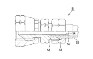
例えば、図8に示される管継手51には、可撓性を有する管体52が接続可能になっている。また、管継手51は、継手本体53、芯金54、スリーブ55及び締め付けナット56を備えている。芯金54は、継手本体53に一体形成され、管体52の先端部内周側に嵌挿される。一方、スリーブ55は管体52の先端部外周側に嵌挿される。また、締め付けナット56は、継手本体53の外周側に螺合することにより、スリーブ55を縮径しつつ継手本体53の一端に接続されるようになっている。これにより、管体52の先端部が、芯金54とスリーブ55とで圧縮されることによってシールされる。
ところが、上記従来技術の管継手51では、締め付けナット56を締め付けた後に流体を流して加圧したときに、管体52の差し込み不足による管体52の抜けが起こる場合があった。しかし、この場合において抜けを防止するために、施工時に差し込み状態の目視確認を行おうとしても、その構造上できなかった。
However, in the above-described prior
本発明は上記の課題に鑑みてなされたものであり、その目的は、管体の差し込み不足を解消することにより、加圧時の管体の抜けを防止することができる管継手を提供することにある。 The present invention has been made in view of the above problems, and an object of the present invention is to provide a pipe joint that can prevent the pipe body from coming off during pressurization by eliminating the insufficient insertion of the pipe body. It is in.
上記課題を解決するために、請求項1に記載の発明では、可撓性を有する管体が接続可能な管継手において、ナット状に形成された大径部を有し、その大径部よりも先端側に配置されるとともに外周部にネジ溝が形成された小径部を有し、流体通路の一部を形成する第1貫通孔を有する継手本体と、前記流体通路の一部を形成する第2貫通孔を有し、前記管体の先端部内周側に嵌挿され、内端側が前記第1貫通孔内に配置される芯金と、前記管体の先端部外周側に嵌挿されるスリーブと、前記継手本体の前記ネジ溝に螺合することにより、前記スリーブを縮径しつつ前記継手本体の管体接続側端に接続する締め付けナットとを備えるとともに、前記締め付けナットの完全締め付け時に前記ナット状の大径部と前記締め付けナットとの間にクリアランスができるように設定し、前記小径部において前記クリアランスができる箇所に、前記継手本体の内側を視認可能とする窓部を形成したことを特徴とする管継手をその要旨とする。
In order to solve the above-mentioned problem, in the invention according to
従って、請求項1に記載の発明によると、窓部から管体が視認可能であるか否かによって、管体が完全に差し込まれているか否かを確認することができる。よって、窓部から管体が視認できなければ、管体を完全に差し込むことにより、管体の差し込み不足を解消することができる。このため、締め付けナットを締め付けた後に流体を流して加圧したときに、管体が抜けてしまうのを防止することができる。 Therefore, according to the first aspect of the present invention, whether or not the tubular body is completely inserted can be confirmed based on whether or not the tubular body is visible from the window portion. Therefore, if the tubular body cannot be visually recognized from the window portion, the insufficient insertion of the tubular body can be solved by completely inserting the tubular body. For this reason, it is possible to prevent the tubular body from coming off when the fluid is supplied and pressurized after tightening the tightening nut.
ここで、可撓性を有する管体としては、ゴム材や樹脂材料からなるホースやチューブが挙げられる。なお、窓部から管体を容易に確認できるようにするためには、管体は有色の材料、即ち、青色、黄色、赤色などに着色された材料からなることが好ましい。また、管体内に塗料を流す場合、塗料の色を確認できるようにするために、管体は無色透明の材料からなっていてもよいが、窓部から見える管体の先端部については着色しておくことが好ましい。 Here, examples of the flexible tube include a hose and a tube made of a rubber material or a resin material. In order to make it easy to confirm the tube from the window, the tube is preferably made of a colored material, that is, a material colored in blue, yellow, red, or the like. In addition, when the paint is allowed to flow through the pipe, the pipe may be made of a colorless and transparent material so that the color of the paint can be confirmed, but the tip of the pipe visible from the window is colored. It is preferable to keep it.
管体を形成する樹脂材料としては、ポリアミド(PA)、ポリエチレンテレフタレート(PET)、ポリカーボネート(PC)、ポリテトラフルオロエチレン(PTFE)などが挙げられる。 Examples of the resin material forming the tubular body include polyamide (PA), polyethylene terephthalate (PET), polycarbonate (PC), polytetrafluoroethylene (PTFE), and the like.
第1貫通孔において芯金が配置されていない部分の直径は、第2貫通孔の直径と略等しくなっていることが好ましい。このようにすれば、流体通路を通過する流体の流体抵抗を低減することができる。 It is preferable that the diameter of the portion where the core metal is not disposed in the first through hole is substantially equal to the diameter of the second through hole. In this way, the fluid resistance of the fluid passing through the fluid passage can be reduced.
また、芯金は、締め付けナットを締め付けたときに変形しない程度の硬さを有する金属材料によって形成されることがよく、特には、継手本体と同じ金属材料を用いて形成されることが好ましい。なお、好適な金属材料の例としては、黄銅や、SUS303、SUS304のようなステンレスなどが挙げられる。 The core metal is preferably formed of a metal material having a hardness that does not deform when the tightening nut is tightened, and is preferably formed using the same metal material as that of the joint body. Examples of suitable metal materials include brass and stainless steel such as SUS303 and SUS304.
なお、芯金は、継手本体と一体に形成されていてもよいが、継手本体とは別体に形成されていることが好ましい。このようにすれば、芯金及び継手本体の寸法管理が容易になり、それらの加工も容易になる。よって、管継手の製造コストを低減することができる。 The cored bar may be formed integrally with the joint body, but is preferably formed separately from the joint body. If it does in this way, the size management of a metal core and a joint main part will become easy, and those processing will also become easy. Therefore, the manufacturing cost of the pipe joint can be reduced.
また、窓部は、小径部においてクリアランスができる箇所の任意の位置に形成することが可能である。好ましくは、窓部は、ネジ溝を避けて配置されることがよい。このようにすれば、締め付けナットを締め付けるときに、締め付けナットが分断されたネジ溝のエッジに引っかかることがない。しかも、締め付けナットを完全に締め付けたときに、窓部が締め付けナットによって覆われてしまうこともない。さらに、窓部は、管体が完全に差し込まれているときに、管体の先端部が位置する箇所に配置されることがよい。このようにすれば、管体の差し込みが少しだけ不足している場合でも、窓部から視認可能な管体の面積が小さくなるため、管体が完全に差し込まれているか否かをより正確に確認することができる。 Further, the window portion can be formed at an arbitrary position where a clearance can be formed in the small diameter portion. Preferably, the window portion may be arranged avoiding the thread groove. In this way, when the tightening nut is tightened, the tightening nut is not caught on the edge of the threaded groove. Moreover, when the tightening nut is completely tightened, the window portion is not covered with the tightening nut. Further, the window portion may be arranged at a position where the tip portion of the tubular body is located when the tubular body is completely inserted. In this way, even if the insertion of the tubular body is a little short, the area of the tubular body visible from the window is reduced, so it is more accurate whether the tubular body is completely inserted or not. Can be confirmed.
なお、窓部としては、小径部を貫通する透孔や、継手本体の管体接続側端の一部を切り欠くことで形成される切欠き部などが挙げられる。また、小径部において透明な材料で形成した部分なども挙げられる。さらに、窓部の形状としては、円形状、矩形状、三角形状などが挙げられる。 Examples of the window portion include a through-hole that penetrates the small-diameter portion, and a notch portion formed by notching a part of the pipe body connection side end of the joint body. Moreover, the part etc. which were formed with the transparent material in a small diameter part are mentioned. Furthermore, examples of the shape of the window include a circular shape, a rectangular shape, and a triangular shape.
請求項2に記載の発明は、請求項1において、前記窓部は円形状の透孔であり、前記透孔は前記継手本体の周方向に沿って等間隔に複数個配置されていることをその要旨とする。 According to a second aspect of the present invention, in the first aspect, the window portion is a circular through hole, and a plurality of the through holes are arranged at equal intervals along a circumferential direction of the joint body. The gist.
従って、請求項2に記載の発明によると、窓部が円形状の透孔であるため、継手本体にドリルを貫通させるだけで、窓部を容易に形成することができる。また、円形状の透孔には応力が集中しにくいため、このような形状の透孔を設けた場合でも継手本体の小径部の強度を維持することができる。さらに、透孔が継手本体の周方向に沿って等間隔に複数個配置されている。そのため、一つの窓部が見えない箇所に配置されている場合でも、別の窓部から継手本体の内側を視認することができる。 Therefore, according to the second aspect of the present invention, since the window portion is a circular through hole, the window portion can be easily formed simply by passing the drill through the joint body. In addition, since stress is unlikely to concentrate in the circular through hole, the strength of the small diameter portion of the joint body can be maintained even when such a through hole is provided. Furthermore, a plurality of through holes are arranged at equal intervals along the circumferential direction of the joint body. Therefore, even when it arrange | positions in the location which cannot see one window part, the inner side of a coupling main body can be visually recognized from another window part.
請求項3に記載の発明は、請求項2において、前記透孔の直径は2mm〜3mmに設定され、前記クリアランスの幅は前記透孔の直径以上の大きさに設定されていることをその要旨とする。
The gist of the invention described in
従って、請求項3に記載の発明によると、透孔の直径が小さすぎないため、透孔から継手本体の内側を容易に視認することができる。また、透孔の直径が大きすぎないため、透孔を設けた場合でも継手本体の小径部の強度を維持することができる。さらに、クリアランスの幅が透孔の直径以上の大きさに設定されているため、締め付けナットを完全に締め付けたときに、透孔が締め付けナットによって覆われてしまうことはない。
Therefore, according to the invention described in
以上詳述したように、請求項1〜3に記載の発明によると、管体の差し込み不足を解消することにより、加圧時の管体の抜けを防止することができる。 As described in detail above, according to the first to third aspects of the present invention, it is possible to prevent the tubular body from coming off during pressurization by eliminating the insufficient insertion of the tubular body.
以下、本発明を具体化した一実施形態を図1〜図7に基づき詳細に説明する。まず、本実施形態の管継手1を備えた自動車用塗装装置について説明する。
DESCRIPTION OF EMBODIMENTS Hereinafter, an embodiment embodying the present invention will be described in detail with reference to FIGS. First, the coating apparatus for motor vehicles provided with the
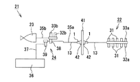
図1に示されるように、塗装装置21は、例えば自動車ボディなどの被塗物を塗装するのに用いられるものであり、バルブユニット24、塗装機23及び色替装置22を備えている。バルブユニット24には、塗装機23に塗料(本実施形態では、水溶性塗料)を供給するための塗装機側系路35bと、排液タンク36に通じるタンク側系路37とが接続されている。また、バルブユニット24は、洗浄時に塗装機側系路35b内にエアを供給するエア供給バルブ32bと、洗浄時に塗装機側系路35b内に溶剤を供給する溶剤供給バルブ33bと、塗料の流れをタンク側系路37側に切り換えるトリガバルブ38と、タンク側系路37を開閉する排液バルブ39とを備えている。
As shown in FIG. 1, the
また、色替装置22は、色替装置側系路35aを介してバルブユニット24に接続されている。色替装置22は、各色の塗料を選択供給する複数の色替バルブ31と、洗浄時に色替装置側系路35a内にエアを供給するエア供給バルブ32aと、洗浄時に色替装置側系路35aに溶剤を供給する溶剤供給バルブ33aとを備えている。
The
色替装置側系路35aは、中継パネル41の両側に設けられた接続管42に、それぞれ後記するホース13が接続された管継手1を接続することによって、配管されている。具体的には、後記するスイベルナット7が有する雌ネジ部7aを、接続管42の外周面に形成された雄ネジ部(図示略)に螺合させることにより、管継手1が接続管42に接続される。なお、両ホース13の基端部は、それぞれ色替装置22またはバルブユニット24のトリガバルブ38に接続される。
The color changer
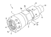
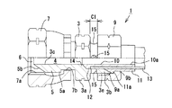
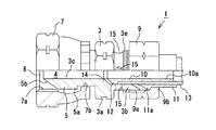
図2,図3に示されるように、管継手1は、主として金属材料(本実施形態ではSUS304)によって構成されており、継手本体3、スイベルナット7、締め付けナット9などを備えている。継手本体3は、ナット状に形成された大径部3a、小径部3b及びニップル部5を同軸上に備えるとともに、それらを貫通する第1貫通孔3cを有している。小径部3bは、大径部3aよりも先端側(図3において右端側)に配置されている。なお、第1貫通孔3cは、塗料が流れる流体通路4の一部を形成している。また、ニップル部5の外周部には環状リブ5aが突設され、同環状リブ5aの先端部(図3において左端部)には、接続管42に圧接するテーパ状のシール部5bが設けられている。
As shown in FIGS. 2 and 3, the
スイベルナット7は、直径が環状リブ5aの外径よりも若干大きく設定され、ニップル部5が回転可能に収容された収容口6を有している。また、スイベルナット7は、直径が環状リブ5aの外径よりも若干小さく設定された貫通孔7bを有している。これにより、環状リブ5aは貫通孔7bを挿通しなくなるため、スイベルナット7が継手本体3から抜けてしまうのが防止される。また、収容口6の内周面には、接続管42に形成された雄ネジ部に螺合する雌ネジ部7aが形成されている。
The
図3に示されるように、前記第1貫通孔3c内には、略円筒状をなす芯金10の内端側が挿入されている。即ち、芯金10は、前記継手本体3とは別体に形成されている。芯金10は、継手本体3と同じ金属材料(本実施形態ではSUS304)によって形成されており、前記流体通路4の一部を形成する第2貫通孔10aを有している。第2貫通孔10aの直径は、第1貫通孔3cにおいて芯金10が配置されていない部分の直径と同一になっている。これにより、流体通路4が全体に亘って等断面形状となるため、流体通路4を通過する塗料の流体抵抗を低減することができる。そして、芯金10の外端部は継手本体3から突出しており、可撓性を有するホース13(管体)の先端部内周側に嵌挿されている。これにより、管継手1にはホース13が接続されるようになっている。なお、ホース13は、着色された樹脂材料(本実施形態では黄色に着色されたポリアミド)によって形成されている。
As shown in FIG. 3, the inner end side of the cored
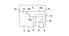
図3,図4に示されるように、芯金10の内端部外周側には、芯金側環状リブ12が突設されている。芯金側環状リブ12の外径は、第1貫通孔3cにおいて芯金10が配置されている部分の直径と略等しくなっている。さらに、芯金側環状リブ12の内端側外周部は、継手本体3の管体接続側端(図3の右端)から離れるに従って芯金10の外径が徐々に小さくなる第2テーパ面12aを有している。なお、本実施形態において、第1貫通孔3c及び第2貫通孔10aの中心軸線に対する第2テーパ面12aの傾斜角度は、45°に設定されている。
As shown in FIGS. 3 and 4, a cored bar-side
図3に示されるように、前記ホース13の先端部外周側には、合成樹脂(本実施形態ではポリアミド)によって形成された略円筒状をなすスリーブ11が嵌挿されている。即ち、スリーブ11の内径は、前記ホース13の外径と略等しくなっている。また、スリーブ11の外端側は継手本体3から突出している。一方、スリーブ11の内端部外周側は、同スリーブ11の内端に行くに従ってスリーブ11の外径が徐々に小さくなる環状テーパ部11aを有している。環状テーパ部11aは、前記小径部3bの内周面とホース13の外周面との隙間内に進入可能になっている。
As shown in FIG. 3, a substantially
前記締め付けナット9の内周面には、小径部3bの外周部に形成されたネジ溝3eに螺合するネジ溝9aが形成されている。このネジ溝9aがネジ溝3eに螺合することにより、締め付けナット9が、スリーブ11を縮径しつつ継手本体3の管体接続側端に接続されるようになっている。これにより、ホース13の先端部が、前記芯金10とスリーブ11とで圧縮されることによってシールされる。また、締め付けナット9は、内径が小径部3bの内径よりも小さく設定された段部9bを有している。この段部9bにスリーブ11の環状テーパ部11aが係合することにより、締め付けナット9からのスリーブ11の抜けが防止される。
On the inner peripheral surface of the tightening
図4,図5に示されるように、継手本体3の内周側には、芯金10の内端が当接しうるストッパ段部14が形成されている。ストッパ段部14は、継手本体3の管体接続側端から離れるに従って前記第1貫通孔3cが徐々に小さくなる第1テーパ面14aを有している。そして、ストッパ段部14に芯金10の内端が当接したとき、第1テーパ面14aに芯金10の前記第2テーパ面12aが面接触するようになっている。即ち、本実施形態において、第1貫通孔3c及び前記第2貫通孔10aの中心軸線に対する第1テーパ面14aの傾斜角度は、第2テーパ面12aの傾斜角度と同じ45°に設定されている。また、ストッパ段部14に芯金10の内端が当接したとき、芯金10の外端がスリーブ11の外端と同じ位置に配置されるようになっている。
As shown in FIGS. 4 and 5, a
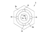
図2,図3に示されるように、前記締め付けナット9の完全締め付け時において、前記大径部3aと締め付けナット9との間には、クリアランスC1ができるようになっている。小径部3bにおいてクリアランスC1ができる箇所には、円形状の透孔15(窓部)が設けられている。なお、本実施形態において、透孔15の直径は3mmに設定されている。また、クリアランスC1の幅は、透孔15の直径以上の大きさ(本実施形態では4mm)に設定されている。
As shown in FIGS. 2 and 3, a clearance C <b> 1 is formed between the large-
図5に示されるように、透孔15は、小径部3bの周方向に沿って90°間隔に4個配置されている。即ち、透孔15は、小径部3bの周方向に沿って等間隔に偶数個配置されている。さらに、各透孔15は、小径部3bに形成された前記ネジ溝3eを避けた位置であって、ネジ溝3eよりも大径部3aに近い位置に設けられている。これら透孔15は、小径部3bの内側を視認可能とするためのものである。なお、透孔15は、小径部3bの径方向(図5において上下方向及び左右方向)にドリルを貫通させることにより、一度に2個ずつ形成可能である。なお、小径部3bを有する継手本体3と芯金10とは別体で構成されているため、小径部3bに対する孔加工時に芯金10に孔が形成されてしまうことはない。従って、芯金10のシール性の低下を未然に防ぐことができる。
As shown in FIG. 5, four through
次に、本実施形態の管継手1にホース13を接続する方法を説明する。
Next, a method for connecting the
まず、ホース13の先端部内周側に芯金10の外端部を嵌挿し、ホース13の先端部外周側にスリーブ11を嵌挿する。そして、ホース13の先端部を継手本体3の第1貫通孔3c内に挿入する。それに伴い、図6に示されるように、継手本体3の小径部3bに対して締め付けナット9を螺着させる。
First, the outer end portion of the cored
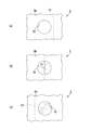
このとき、第1貫通孔3c内に挿入されるホース13の先端は、透孔15よりも手前側の位置、即ち、透孔15よりも継手本体3の管体接続側端に近い位置(図7(a)参照)から、透孔15が設けられている位置(図7(b)参照)に移動する。なお、図7では説明の便宜上、ホース13の先端部にハッチングを付けて表している。そして最終的には、ホース13の先端は、透孔15よりも奥側の位置(図7(c)参照)へと移動する。その結果、芯金10の内端がストッパ段部14に当接し、締め付けナット9が、スリーブ11を縮径しつつ継手本体3の管体接続側端に接続される。これにより、ホース13の先端部が、芯金10とスリーブ11とで圧縮されることによってシールされる。また、スリーブ11の環状テーパ部11aは、締め付けナット9の螺着に伴い、小径部3bの内周面とホース13の外周面との隙間内に進入する。これにより、スリーブ11がさらに縮径されてホース13の先端部を押圧するため、ホース13の固定状態がより強固になる。
At this time, the tip of the
その後、ホース13が取り付けられた管継手1のスイベルナット7を、図1に示される接続管42の端面に押し付けて螺着させることにより、管継手1が接続管42に固定される。なお、継手本体3に対してスイベルナット7が回動可能に設けられる。よって、管継手1に固定されたホース13がスイベルナット7の回動に伴って捩れるのを防止しながら配管することができる。
After that, the
従って、本実施形態によれば以下の効果を得ることができる。 Therefore, according to the present embodiment, the following effects can be obtained.
(1)本実施形態の管継手1によれば、透孔15からホース13が視認可能であるか否かをもって、ホース13が完全に差し込まれているか否かを確認することができる。よって、透孔15からホース13が全く視認できない場合(図7(a)参照)や、透孔15から視認可能なホース13の面積が透孔15の面積よりも小さい場合(図7(b)参照)には、差し込みが不完全であると把握することができる。よって、この場合には、ホース13を完全に差し込んで図7(c)に示す状態にすることにより、ホース13の差し込み不足を解消することができる。このため、締め付けナット9を締め付けた後に塗料を流して加圧したときに、ホース13が抜けてしまうのを防止することができる。ゆえに、ホース13内の塗料が飛び散ることにより、管継手1の周囲が汚れてしまうのを防止できる。
(1) According to the
(2)本実施形態では、芯金10が継手本体3とは別体で形成されていることから、芯金10及び継手本体3の寸法管理が容易になり、それらの加工も容易になる。しかも、本実施形態では、透孔15が等間隔に偶数個(4個)配置されているため、小径部3bの径方向(図5において上下方向及び左右方向)にドリルを貫通させることにより、透孔15を一度に2個ずつ形成することができる。よって、継手本体3の製作において、透孔15を形成するためにドリルを貫通させる回数が、透孔15の数の半分で済む。従って、管継手1の製造コストを低減することができる。
(2) In this embodiment, since the cored
(3)本実施形態では、芯金10が継手本体3とは別体で形成されているため、締め付けナット9を取り外すだけで、ホース13に嵌挿された芯金10を継手本体3から容易に抜き取ることができる。よって、継手本体3からのホース13の抜き取りが容易になる。
(3) In the present embodiment, since the cored
なお、本発明の実施形態は以下のように変更してもよい。 In addition, you may change embodiment of this invention as follows.
・上記実施形態では、管継手1は、塗装装置21の色替装置側系路35aの配管を行うために、中継パネル41の両側に設けられた接続管42とホース13との接続部分に用いられていた。しかし、管継手1は、色替装置22とホース13との接続部分や、バルブユニット24とホース13との接続部分などに用いられていてもよい。即ち、管継手1内を流れる流体は、塗料に限らず、塗装機23から塗料を噴出させるためのエアや、塗装装置21内に残存した塗料を洗浄して除去する溶剤などであってもよい。
In the above embodiment, the
・上記実施形態では、管継手1は、塗装装置21において、塗料を塗装機23に供給する色替装置側系路35aに用いられていた。しかし、管継手1は、半導体製造装置において洗浄用の水を供給及び循環させる系路、化学プラントにおいて各種薬液を供給及び循環させる系路、及び、油圧機器において油を供給及び循環させる経路などに用いられていてもよい。
In the above embodiment, the
・上記実施形態の管継手1は、接続管42に対してホース13をストレートに接続して配管する管継手であったが、ティーズ型、エルボ型の管継手などに変更してもよい。また、上記実施形態の管継手1は、スイベルナット7を備えるスイベル継手でなくてもよい。
-Although the
・上記実施形態では、透孔15は小径部3bに4個配置されていたが、1〜3個配置されていてもよいし、5個以上配置されていてもよい。また、上記実施形態では、透孔15が、ネジ溝3eを避けた位置であって、ネジ溝3eよりも大径部3aに近い位置に設けられていた。しかし、透孔15は、小径部3bにおいてクリアランスC1ができる箇所の任意の位置であれば、どこに設けられていてもよい。
In the above embodiment, four through
次に、特許請求の範囲に記載された技術的思想のほかに、前述した実施形態によって把握される技術的思想を以下に列挙する。 Next, in addition to the technical ideas described in the claims, the technical ideas grasped by the embodiment described above are listed below.
(1)請求項1乃至3のいずれか1項において、前記管体は有色の樹脂材料からなること。
(1) In any one of
(2)請求項2または3において、前記透孔は前記継手本体の前記ネジ溝を避けて配置されていること。
(2) In
(3)請求項1乃至3のいずれか1項において、前記芯金を前記継手本体と別体で形成したこと。
(3) In any one of
(4)請求項1乃至3のいずれか1項において、前記芯金を前記継手本体と別体で形成し、前記芯金の内端が当接しうるストッパ段部を前記継手本体の内周側に形成し、そのストッパ段部に前記芯金の内端が当接したときに前記芯金の外端が前記スリーブの外端と略同じ位置に配置されるように構成したこと。
(4) In any one of
(5)請求項1乃至3のいずれか1項において、前記第1貫通孔において前記芯金が配置されていない部分の直径と、前記第2貫通孔の直径とが略等しいこと。このようにすれば、流体通路を通過する流体の流体抵抗を低減することができる。
(5) In any one of
(6)可撓性を有する管体が接続可能な管継手において、ナット状に形成された大径部を有し、その大径部よりも先端側に配置されるとともに外周部にネジ溝が形成された小径部を有し、流体通路の一部を形成する第1貫通孔を有する継手本体と、前記継手本体が備えるニップル部を回転可能に収容する収容口を有するスイベルナットと、前記流体通路の一部を形成する第2貫通孔を有し、前記管体の先端部内周側に嵌挿され、内端側が前記第1貫通孔内に配置される芯金と、前記管体の先端部外周側に嵌挿されるスリーブと、前記継手本体の前記ネジ溝に螺合することにより、前記スリーブを縮径しつつ前記継手本体の管体接続側端に接続する締め付けナットとを備えるとともに、前記締め付けナットの完全締め付け時に前記ナット状の大径部と前記締め付けナットとの間にクリアランスができるように設定し、前記小径部において前記クリアランスができる箇所に、前記継手本体の内側を視認可能とする窓部を形成したことを特徴とする管継手。 (6) In a pipe joint to which a flexible pipe body can be connected, the pipe joint has a large-diameter portion formed in a nut shape, and is disposed on the tip side of the large-diameter portion and has a thread groove on the outer peripheral portion. A joint body having a formed small diameter part and having a first through hole forming a part of a fluid passage; a swivel nut having a receiving port for rotatably housing a nipple part included in the joint body; and the fluid A metal core having a second through hole forming a part of the passage, fitted into the inner peripheral side of the distal end portion of the tubular body, the inner end side being disposed in the first through hole, and the distal end of the tubular body A sleeve fitted into the outer periphery of the joint, and a tightening nut connected to the tube connection side end of the joint body while reducing the diameter of the sleeve by screwing into the thread groove of the joint body, When fully tightening the tightening nut, A pipe joint characterized in that a clearance is set between the clamping nut and the tightening nut, and a window portion is formed in the small diameter portion where the clearance can be seen so that the inside of the joint body can be visually recognized. .
1…管継手
3…継手本体
3a…大径部
3b…小径部
3c…第1貫通孔
3e…ネジ溝
4…流体通路
9…締め付けナット
10…芯金
10a…第2貫通孔
11…スリーブ
13…管体としてのホース
15…窓部としての透孔
C1…クリアランス
DESCRIPTION OF
Claims (3)
ナット状に形成された大径部を有し、その大径部よりも先端側に配置されるとともに外周部にネジ溝が形成された小径部を有し、流体通路の一部を形成する第1貫通孔を有する継手本体と、
前記流体通路の一部を形成する第2貫通孔を有し、前記管体の先端部内周側に嵌挿され、内端側が前記第1貫通孔内に配置される芯金と、
前記管体の先端部外周側に嵌挿されるスリーブと、
前記継手本体の前記ネジ溝に螺合することにより、前記スリーブを縮径しつつ前記継手本体の管体接続側端に接続する締め付けナットと
を備えるとともに、
前記締め付けナットの完全締め付け時に前記ナット状の大径部と前記締め付けナットとの間にクリアランスができるように設定し、前記小径部において前記クリアランスができる箇所に、前記継手本体の内側を視認可能とする窓部を形成したことを特徴とする管継手。 In a pipe joint to which a flexible pipe body can be connected,
A large-diameter portion formed in a nut shape is disposed on the tip side of the large-diameter portion and has a small-diameter portion in which a thread groove is formed on the outer peripheral portion, and forms a part of the fluid passage. A joint body having one through hole;
A metal core having a second through hole forming a part of the fluid passage, being fitted into the inner peripheral side of the distal end of the tubular body, and having an inner end side disposed in the first through hole;
A sleeve fitted into the outer peripheral side of the distal end of the tubular body;
A fastening nut that is connected to the tube connection side end of the joint body while reducing the diameter of the sleeve by being screwed into the thread groove of the joint body,
It is set so that a clearance can be formed between the nut-shaped large diameter portion and the tightening nut when the tightening nut is completely tightened, and the inside of the joint body can be visually recognized at a position where the clearance can be formed in the small diameter portion. A pipe joint characterized in that a window portion is formed.
Priority Applications (1)
| Application Number | Priority Date | Filing Date | Title |
|---|---|---|---|
| JP2004109761A JP2005291430A (en) | 2004-04-02 | 2004-04-02 | Pipe coupling |
Applications Claiming Priority (1)
| Application Number | Priority Date | Filing Date | Title |
|---|---|---|---|
| JP2004109761A JP2005291430A (en) | 2004-04-02 | 2004-04-02 | Pipe coupling |
Publications (1)
| Publication Number | Publication Date |
|---|---|
| JP2005291430A true JP2005291430A (en) | 2005-10-20 |
Family
ID=35324579
Family Applications (1)
| Application Number | Title | Priority Date | Filing Date |
|---|---|---|---|
| JP2004109761A Pending JP2005291430A (en) | 2004-04-02 | 2004-04-02 | Pipe coupling |
Country Status (1)
| Country | Link |
|---|---|
| JP (1) | JP2005291430A (en) |
Cited By (1)
| Publication number | Priority date | Publication date | Assignee | Title |
|---|---|---|---|---|
| JP2010025194A (en) * | 2008-07-17 | 2010-02-04 | Hino Motors Ltd | Flare nut |
Citations (2)
| Publication number | Priority date | Publication date | Assignee | Title |
|---|---|---|---|---|
| JPH0315905Y2 (en) * | 1987-03-30 | 1991-04-05 | ||
| JPH11351464A (en) * | 1999-06-04 | 1999-12-24 | Uekkusu:Kk | Pipe joint |
-
2004
- 2004-04-02 JP JP2004109761A patent/JP2005291430A/en active Pending
Patent Citations (2)
| Publication number | Priority date | Publication date | Assignee | Title |
|---|---|---|---|---|
| JPH0315905Y2 (en) * | 1987-03-30 | 1991-04-05 | ||
| JPH11351464A (en) * | 1999-06-04 | 1999-12-24 | Uekkusu:Kk | Pipe joint |
Cited By (1)
| Publication number | Priority date | Publication date | Assignee | Title |
|---|---|---|---|---|
| JP2010025194A (en) * | 2008-07-17 | 2010-02-04 | Hino Motors Ltd | Flare nut |
Similar Documents
| Publication | Publication Date | Title |
|---|---|---|
| US6708717B1 (en) | Flushing system for air conditioning drainage pipes | |
| JP5360619B2 (en) | Pipe fitting | |
| US9200740B2 (en) | Piping system drain down tool | |
| US20150144717A1 (en) | Conduit With Connector And Assembly Thereof | |
| US7703814B2 (en) | Universal quick connection unit for connecting pipe to hydraulic or pneumatic tool | |
| US20130269806A1 (en) | Vee Manifold | |
| EP3259077B1 (en) | Sprayer adapter | |
| US8286275B2 (en) | Drain clean-out assembly and method of using | |
| US9661807B2 (en) | Conduit with connector and assembly thereof | |
| JP2005291430A (en) | Pipe coupling | |
| US7055865B2 (en) | Lateral connection system | |
| JP2005291429A (en) | Pipe coupling | |
| US20160312918A1 (en) | Hose Restraint System and Method for Using the Same | |
| JP2012189093A (en) | Hose joint and manufacturing method thereof | |
| KR200457869Y1 (en) | Air ejector with slide valve | |
| JP2008071565A (en) | Connection structure between lead wire and heater wire | |
| GB2535741A (en) | Pipe coupling for multilayer pipes | |
| KR101313112B1 (en) | Saddle for water works | |
| CN211315392U (en) | Double-channel pipe-in-pipe and water supply equipment adopting same | |
| US20090058082A1 (en) | Two-part quick connect retention attachment for flexible tubing in a water supply system | |
| JP2011041891A (en) | Brush for pressure coating system | |
| US7111820B2 (en) | Inline connector for a plumbing conduit | |
| CN210890206U (en) | Quick-connecting ball valve | |
| US20090058084A1 (en) | Adaptor for quick connect coupling in water supply system | |
| JP2008019980A (en) | Hose connection pipe joint |
Legal Events
| Date | Code | Title | Description |
|---|---|---|---|
| A621 | Written request for application examination |
Effective date: 20070330 Free format text: JAPANESE INTERMEDIATE CODE: A621 |
|
| A977 | Report on retrieval |
Effective date: 20091019 Free format text: JAPANESE INTERMEDIATE CODE: A971007 |
|
| A131 | Notification of reasons for refusal |
Free format text: JAPANESE INTERMEDIATE CODE: A131 Effective date: 20091030 |
|
| A02 | Decision of refusal |
Free format text: JAPANESE INTERMEDIATE CODE: A02 Effective date: 20100330 |