JP2005291446A - Pipe joint - Google Patents
Pipe joint Download PDFInfo
- Publication number
- JP2005291446A JP2005291446A JP2004110367A JP2004110367A JP2005291446A JP 2005291446 A JP2005291446 A JP 2005291446A JP 2004110367 A JP2004110367 A JP 2004110367A JP 2004110367 A JP2004110367 A JP 2004110367A JP 2005291446 A JP2005291446 A JP 2005291446A
- Authority
- JP
- Japan
- Prior art keywords
- resin tube
- lock member
- valve
- tube
- peripheral surface
- Prior art date
- Legal status (The legal status is an assumption and is not a legal conclusion. Google has not performed a legal analysis and makes no representation as to the accuracy of the status listed.)
- Pending
Links
- 229920005989 resin Polymers 0.000 claims abstract description 70
- 239000011347 resin Substances 0.000 claims abstract description 70
- 229920003002 synthetic resin Polymers 0.000 claims description 5
- 239000000057 synthetic resin Substances 0.000 claims description 5
- 230000002093 peripheral effect Effects 0.000 abstract description 30
- 230000001105 regulatory effect Effects 0.000 abstract description 6
- 230000007246 mechanism Effects 0.000 description 25
- 238000004891 communication Methods 0.000 description 13
- 239000012530 fluid Substances 0.000 description 12
- XLYOFNOQVPJJNP-UHFFFAOYSA-N water Substances O XLYOFNOQVPJJNP-UHFFFAOYSA-N 0.000 description 11
- 238000000034 method Methods 0.000 description 6
- 239000000463 material Substances 0.000 description 5
- 230000008569 process Effects 0.000 description 5
- 230000006835 compression Effects 0.000 description 4
- 238000007906 compression Methods 0.000 description 4
- 238000010438 heat treatment Methods 0.000 description 4
- 239000002184 metal Substances 0.000 description 4
- 230000008878 coupling Effects 0.000 description 3
- 238000010168 coupling process Methods 0.000 description 3
- 238000005859 coupling reaction Methods 0.000 description 3
- 238000006073 displacement reaction Methods 0.000 description 3
- BZHJMEDXRYGGRV-UHFFFAOYSA-N Vinyl chloride Chemical compound ClC=C BZHJMEDXRYGGRV-UHFFFAOYSA-N 0.000 description 2
- 230000009471 action Effects 0.000 description 2
- 238000013459 approach Methods 0.000 description 2
- 230000033228 biological regulation Effects 0.000 description 2
- 229920003020 cross-linked polyethylene Polymers 0.000 description 2
- 239000004703 cross-linked polyethylene Substances 0.000 description 2
- 238000003780 insertion Methods 0.000 description 2
- 230000037431 insertion Effects 0.000 description 2
- 210000002445 nipple Anatomy 0.000 description 2
- 229920002635 polyurethane Polymers 0.000 description 2
- 239000004814 polyurethane Substances 0.000 description 2
- 230000015572 biosynthetic process Effects 0.000 description 1
- 230000007423 decrease Effects 0.000 description 1
- 230000003247 decreasing effect Effects 0.000 description 1
- 238000001035 drying Methods 0.000 description 1
- 238000012986 modification Methods 0.000 description 1
- 230000004048 modification Effects 0.000 description 1
- 230000000149 penetrating effect Effects 0.000 description 1
- 238000005086 pumping Methods 0.000 description 1
Images

Landscapes
- Joints With Pressure Members (AREA)
- Joints That Cut Off Fluids, And Hose Joints (AREA)
Abstract
Description
本発明は、管継手に関するものである。 The present invention relates to a pipe joint.
給水、排水、散水等に際して水等の流体を圧送する作業において、ホースを接続するための管継手として、従来、外周に複数のテーパ状の段差を連続させた筍状のニップル(管部)を有しており、この筍状のニップルをホースに差し込んでテーパ状の鋭角な段差にホースの内周を食い込ませ、さらに、ホースの外周を金属製のホースバンドで締め付けることによって、ホースの抜止めと防水シールを行うようになっていた。尚、テーパ状の段差に樹脂チューブを食い込ませて嵌める形態の管継手としては、特許文献1に開示されているものがある。
上記従来の管継手では、ホースバンドの締付け手段として、ネジをねじ込むという方法がとられていたため、ネジの頭部の小さい溝に工具の先端を嵌め込むという煩わしい作業が必要となり、作業性が良くないという問題があった。 In the above conventional pipe joint, the method of screwing in the hose band has been adopted as a means for tightening the hose band. There was no problem.
また、ネジの緩みによってホースバンドの締付けが甘くなり、ホースが外れたり、流体の漏れが発生したりする虞もあった。 In addition, the hose band tightens loosely due to the loosening of the screws, and the hose may come off or fluid leakage may occur.
尚、上記問題は、床暖房設備等、合成樹脂製のホースやチューブに接続される手段として広く使用される管継手においても、同様に解決が望まれる。 The above problem is similarly desired to be solved in pipe joints widely used as means for connecting to synthetic resin hoses and tubes such as floor heating equipment.
本発明は上記のような事情に基づいて完成されたものであって、作業性と信頼性に優れた管継手を提供することを目的とする。 This invention is completed based on the above situations, Comprising: It aims at providing the pipe joint excellent in workability | operativity and reliability.
上記の目的を達成するための手段として、請求項1の発明は、合成樹脂製のチューブを接続させるものであって、嵌合管と雄ネジ部とを有する筒状の継手本体と、内周にテーパ面を有し、前記雄ネジ部に螺合された筒状のロック部材と、前記嵌合管との間に径方向の隙間を空けるとともに前記テーパ面と対応するように配された略C字形の締付リングとを備えてなり、前記樹脂チューブの端末部を、前記嵌合管と前記締付リングとの間に差し込んだ状態で、前記ロック部材を螺進させて前記テーパ面の傾斜により前記締付リングを縮径変形させることで、前記樹脂チューブを締め付けて抜け規制する構成とされているところに特徴を有する。 As means for achieving the above object, the invention of claim 1 is to connect a tube made of synthetic resin, and has a cylindrical joint body having a fitting tube and a male screw portion, an inner circumference And a cylindrical lock member screwed into the male threaded portion, and a gap in the radial direction between the fitting tube and an approximately arranged to correspond to the tapered surface A C-shaped clamping ring, and with the terminal portion of the resin tube inserted between the fitting tube and the clamping ring, the lock member is screwed to make the taper surface The present invention is characterized in that the diameter of the fastening ring is reduced by an inclination so that the resin tube is tightened to be prevented from being pulled out.
尚、ここで、樹脂チューブとは、手で湾曲させることのできる程度の比較的剛性の低い材質(例えば、架橋ポリエチレン、ポリウレタン)のもの、手で曲げたり湾曲させたりすることが困難な剛性の高い一般にパイプと称されるもの、比較的柔軟に変形し得る材質(例えば、塩化ビニル)からなる一般にホースと称されるものも含む。 Here, the resin tube is made of a material with relatively low rigidity (for example, cross-linked polyethylene or polyurethane) that can be bent by hand, and has a rigidity that is difficult to bend or curve by hand. Also included are those generally referred to as pipes and those generally referred to as hoses made of a material that can be deformed relatively flexibly (for example, vinyl chloride).
また、第2の発明として、請求項1に記載のものにおいて、継手本体に連通する流路を開閉可能なバルブ機構を備えている構成とすることができる。
かかる構成によれば、継手本体及び継手本体に接続されるチューブによって構成される流路を自在に開閉することができる。
Further, as a second invention, in the invention described in claim 1, a valve mechanism capable of opening and closing a flow path communicating with the joint body can be provided.
According to this structure, the flow path comprised by the joint main body and the tube connected to a joint main body can be opened and closed freely.
また、第3の発明として、請求項1または第2の発明に記載のものにおいて、継手本体に径方向の変位を可能とされたロックボールを設け、前記継手本体に連結されるプラグに対しロックボールを係止させることで、プラグを離脱規制する構成とすることができる。
かかる構成によれば、プラグに取り付けたホースなどを傷つけることなく、継手本体に対して着脱することができる。
According to a third aspect of the present invention, in the first or second aspect of the present invention, the joint body is provided with a lock ball that can be displaced in the radial direction, and locked to the plug connected to the joint body. By locking the ball, the plug can be regulated to be detached.
According to this configuration, the hose attached to the plug can be attached to and detached from the joint body without damaging the hose.
また、第4の発明として、請求項第3の発明において、プラグにおける継手本体との接続側と反対側の端部に、嵌合管とテーパ面を有するロック部材と締付リングとを備えたロック機構を設ける構成としてもよい。
かかる構成によれば、プラグにおけるホースなどの接続部分の外径を小さくすることができる。
Further, as a fourth invention, in the third invention, a plug is provided with a fitting member, a lock member having a tapered surface, and a tightening ring at an end of the plug opposite to the connection side with the joint body. It is good also as a structure which provides a lock mechanism.
According to such a configuration, the outer diameter of a connecting portion such as a hose in the plug can be reduced.
<請求項1の発明>
樹脂チューブの接続に際しては、樹脂チューブを包囲する比較的外径の大きい筒状のロック部材を螺進させるだけでよいので、ネジの頭部の小さい溝に工具の先端を嵌めるような煩わしさがなく、作業性に優れる。また、樹脂チューブを締め付けて接続した状態では、締付リングの外周面とロック部材のテーパ面との間に生じる摩擦抵抗によって、ロック部材の緩みが規制されるとともに、樹脂チューブの外周面と締付リングの内周面との間に生じる摩擦抵抗及び樹脂チューブの内周面と嵌合管の外周面との間に生じる摩擦抵抗によって、樹脂チューブの抜けが規制されるので、確実に樹脂チューブを接続状態にロックしておくことができる。
<Invention of Claim 1>
When connecting the resin tube, it is only necessary to screw the cylindrical lock member having a relatively large outer diameter surrounding the resin tube, so that the troublesomeness of fitting the tip of the tool into the small groove on the head of the screw is eliminated. There is no workability. In addition, in a state where the resin tube is tightened and connected, the frictional resistance generated between the outer peripheral surface of the tightening ring and the taper surface of the lock member regulates loosening of the lock member and tightens the outer periphery of the resin tube. The resin tube is securely pulled out by the frictional resistance generated between the inner peripheral surface of the attached ring and the frictional resistance generated between the inner peripheral surface of the resin tube and the outer peripheral surface of the fitting tube. Can be locked in a connected state.
<実施形態1>
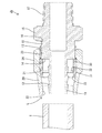
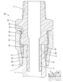
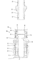
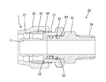
以下、本発明を具体化した実施形態1を図1乃至図4を参照して説明する。本実施形態1の管継手Jaは、樹脂チューブTを容易且つ確実に接続するためのものであり、具体的には、水等の流体を給水、排水、散水等のために圧送する際に、樹脂チューブTを接続する手段として使用される。その他、熱交換を利用した床暖房設備において、マット内に配索した温水流通用の樹脂チューブTを給湯器のヘッダーから延びた配管に接続する手段、又はマット側から延びた樹脂チューブTをヘッダーに接続するための手段として使用される。また、床暖房設備以外にも、浴室内暖房設備、浴室内乾燥設備、台所や洗面所への給湯設備等の多様の給湯設備における樹脂チューブTの接続手段としても使用することができるものである。ここで、樹脂チューブTとは、比較的剛性の高い材質(例えば、架橋ポリエチレン、ポリウレタン)のものや、比較的柔軟に変形し得る材質(例えば、塩化ビニル)からなる一般にホースと称されるものも含む。
<Embodiment 1>
A first embodiment of the present invention will be described below with reference to FIGS. The pipe joint Ja of the first embodiment is for connecting the resin tube T easily and reliably. Specifically, when a fluid such as water is pumped for water supply, drainage, watering, etc., Used as means for connecting the resin tube T. In addition, in floor heating equipment using heat exchange, means for connecting the resin tube T for circulating hot water routed in the mat to a pipe extending from the header of the water heater, or the resin tube T extending from the mat side as a header Used as a means to connect to. In addition to floor heating equipment, it can also be used as a connecting means for the resin tube T in various hot water supply equipment such as heating equipment in the bathroom, drying equipment in the bathroom, and hot water supply equipment to the kitchen and washroom. . Here, the resin tube T is a material generally called a hose made of a material having relatively high rigidity (for example, cross-linked polyethylene, polyurethane) or a material that can be deformed relatively flexibly (for example, vinyl chloride). Including.
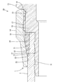
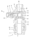
管継手Jaは、継手本体10とロック部材20と締付リング30を備えて構成されている。継手本体10は、金属製であって、全体として概ね円筒形をなす。継手本体10の前端部には、円筒状をなす嵌合管11が形成されている。嵌合管11の外周には、前方に向かって縮径する形態のテーパ状(筍状)をなす複数の段差部12が、軸線方向(前後方向)に一定ピッチで並んで形成されている。段差部12の最大外径は樹脂チューブTの内径よりも大きい寸法とされている。
The pipe joint Ja includes a
継手本体10の外周における軸線方向略中央位置には雄ネジ部13が形成されている。雄ネジ部13の外径は嵌合管11の外径よりも大きく、雄ネジ部13の前端と嵌合管11の後端との境界に形成された段差部の前面は、軸線方向(継手本体10に対する樹脂チューブTの差込み方向)と直角な突当面14となっている。継手本体10の外周における雄ネジ部13よりも後方の位置には、外形が六角形をなす治具嵌合部15が形成されており、この治具嵌合部15の前面はストッパ16となっている。また、継手本体10の後端部外周には、管継手Jaを樹脂チューブTの図示しない接続相手(例えば、給水源の接続孔や給湯器のヘッダーの接続孔)に接続するためのテーパ状ネジ部17が形成されている。
A
ロック部材20は、金属製であって、全体として概ね円筒状をなす。ロック部材20の内周には、前方に向かって縮径するテーパ面21が形成されている。ロック部材20の内周前端部には、テーパ面21の前端から径方向内側へ張り出した形態の抜止部22が形成されている。抜止部22の内径は樹脂チューブTの外径よりも僅かに大きい寸法である。また、ロック部材20の内周後端部には雌ネジ部23が形成されており、ロック部材20は、雌ネジ部23を雄ネジ部13に螺合させることによって継手本体10に取り付けられている。取り付けられたロック部材20のテーパ面21は、嵌合管11の外周に対して同心状に且つ筒状空間を空けて対応している。尚、ロック部材20の外周には、外形が六角形をなす治具嵌合部24が形成されている。
The
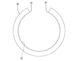
締付リング30は、合成樹脂製であって、全体として略C字形をなす。変形していない自由状態(図3を参照)では、継手本体10と同心の円弧形をなし、周方向における両端部の間に適当な角度の間隔が空いている。また、自由状態における締付リング30の内径は樹脂チューブTの外径よりも僅かに大きい寸法とされている。締付リング30の外周には、前方へ向かって縮径するテーパ状の被押圧面31が形成されている。この被押圧面31の勾配はロック部材20のテーパ面21と同じ角度とされている。
The fastening
また、締付リング30の内周には、周方向に沿って延びる1本の溝32が形成されている。前後方向において、溝32は、最も後方の段差部12の傾斜面と対応するように位置している。周方向における溝32の形成領域は、締付リング30の周方向両端部を除いた範囲となっている。締付リング30の内周面における溝32の前後両開口縁は、段差状を呈しており、この段差部のエッジが樹脂チューブTの外周に食い込むようになっている。
A
また、締付リング30の前端部内周には、前方に向かって拡径するテーパ状のガイド斜面33が形成されている。かかる締付リング30は、ロック部材20の内周に装着されており、装着された締付リング30は抜止部22によって前方への抜けを規制されている。
In addition, a
上記した嵌合管11と雄ネジ部13とを有する筒状の継手本体10と、内周にテーパ面21を有していて雄ネジ部13に螺合された筒状のロック部材20と、嵌合管11との間に径方向の隙間を空けるとともにテーパ面21と対応するように配された略C字形の締付リング30とによって、ロック機構Lが構成されている。後述するように、このロック機構Lによれば、樹脂チューブTの端末部を、嵌合管11と締付リング30との間に差し込んだ状態で、ロック部材20を螺進させてテーパ面21の傾斜により締付リング30を縮径変形させることで、樹脂チューブTを締め付けて抜け規制できるようになっている。
A
次に、本実施形態の作用を説明する。
管継手Jaに樹脂チューブTを接続する際には、ロック部材20を継手本体10のストッパ16よりも前方の位置で待機させ、締付リング30をほぼ自由状態としておく。このとき、締付リング30は、その被押圧面31をテーパ面21の後端側領域、即ちテーパ面21のうちの内径の大きい領域と近接して対応又は面接触させるように位置し、締付リング30の後端面が継手本体10の突当面14に当接又は接近して対向している。
Next, the operation of this embodiment will be described.
When the resin tube T is connected to the pipe joint Ja, the
この状態で、樹脂チューブTの端末部を前方からロック部材20内の締付リング30と嵌合管11との間に挿入し、樹脂チューブTの差込み方向先端を突当面14に当接させるか、若しくは当接する直前の位置まで進ませる。この継手本体10内に差し込まれた樹脂チューブTの内周は嵌合管11のテーパ状の段差部12に食い込んだ状態となる。この後、継手本体10の治具嵌合部15とロック部材20の治具嵌合部24に治具(図示せず)を嵌め、継手本体10に対してロック部材20を回転させることで、ロック部材20を後方(ストッパ16に接近する方向)へ螺進させる。螺進の過程では、ロック部材20のテーパ面21が、締付リング30の被押圧面31に摺接しつつ径方向内側へ押圧し、この押圧によって締付リング30が次第に縮径変形していく。縮径変形する過程では、締付リング30の内周が樹脂チューブTの外周に対して面接触状態で密着するとともに、溝32の開口縁のエッジが樹脂チューブTの外周に食い込む。これと同時に、嵌合管11に対する樹脂チューブTの内周の食い込みの度合いが増していくとともに、嵌合管11の外周と樹脂チューブTの内周との間の面接触領域が拡大していく。
In this state, the end portion of the resin tube T is inserted between the
また、締め付ける過程において、締付リング30の外周にはロック部材20との間の摩擦によって回転力(周方向に変位する力)が付与されるのに対し、樹脂チューブTの内周には嵌合管11が面接触状態で食い込んで回転を阻止する力が付与されるため、樹脂チューブTが締付リング30と嵌合管11との間で捻れることが懸念される。しかし、本実施形態では、締付リング30の溝32が樹脂チューブTの外周に食い込んでおり、この食い込み力が、締付リング30の外周の被押圧面31とロック部材20の内周のテーパ面21との間の面接触に起因して生じる摩擦抵抗よりも大きくなっている。したがって、ロック部材20が回転しても、締付リング30とロック部材20との間で滑りを生じるだけであって、樹脂チューブTと締付リング30との間での周方向への滑り、即ち締付リング30の周方向への変位(回転)は規制され、ひいては、樹脂チューブTの捻れが防止されている。
Further, in the tightening process, a rotational force (a force displaced in the circumferential direction) is applied to the outer periphery of the tightening
そして、ロック部材20をストッパ16に突き当たるまで螺進させると、接続作業が完了する。接続が完了した状態では、締付リング30が縮径して樹脂チューブTを径方向内側へ締め付けることにより、樹脂チューブTが締付リング30と嵌合管11との間で概ね全周に亘って均一に挟圧され、この挟圧、即ち締付けにより、樹脂チューブTの内周と嵌合管11との間が液密状にシールされるとともに、テーパ状の段差の食い込みによって樹脂チューブTが継手本体10に対して抜止めされる。
Then, when the
尚、接続完了状態において、締付リング30の周方向両端は、互いに接近するものの、当接することはない。また、締付リング30の内周における周方向両端縁には弧状のテーパ縁部34が形成されているので、締付リング30が縮径してその両端部が接近したときに、その締付リング30の両端部の間で樹脂チューブTの外周が摘まれるように挟まれる虞はない。
In the connection completed state, both ends in the circumferential direction of the tightening
上述のように本実施形態の管継手Jaは、樹脂チューブTの接続に際して、樹脂チューブTを包囲する比較的外径の大きい筒状のロック部材20を螺進させるようになっているので、ネジの頭部の小さい溝に工具の先端を嵌めるような煩わしさがなく、作業性に優れている。
また、樹脂チューブTを締め付けて接続した状態では、面接触している締付リング30の外周面とロック部材20のテーパ面21との間に生じる摩擦抵抗によって、ロック部材20の緩みが規制されるとともに、面接触している樹脂チューブTの外周面と締付リング30の内周面との間に生じる摩擦抵抗及び同じく面接触している樹脂チューブTの内周面と嵌合管11の外周面との間に生じる摩擦抵抗によって、樹脂チューブTの抜けが規制されるので、確実に樹脂チューブTを接続状態にロックしておくことができる。
さらに、樹脂チューブTの外周を略C字形の締付リング30と筒状のロック部材20によって締め付けるようになっているので、操作部が径方向に突出した形態のホースバンドで締め付けるものに比べて、管継手Jaの外径を小さくすることができる。
As described above, the pipe joint Ja of the present embodiment is configured to screw the
In the state where the resin tube T is tightened and connected, the looseness of the
Furthermore, since the outer periphery of the resin tube T is tightened by a substantially C-shaped
<実施形態2>
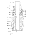
次に、本発明を具体化した実施形態2を図5及び図6を参照して説明する。本実施形態2の管継手Jbは、例えば散水用のホース(樹脂チューブ)に取り付けられるプラグ50をワンタッチで接続できるようにしたものである。管継手Jbの前端部には、実施形態1と同じ構成のロック機構Lが設けられており、管継手Jbの後端部には、連結機構40が設けられている。
<Embodiment 2>
Next, a second embodiment of the present invention will be described with reference to FIGS. The pipe joint Jb of the second embodiment is configured such that, for example, a
連結機構40は、継手本体41の後端部に形成された円筒部42と、この円筒部42の保持孔43に径方向への変位を可能に収容されたロックボール44と、円筒部42の外周に沿って前後方向(軸方向)に往復スライド可能なスライダ45とを備えている。スライダ45の内周面には逃がし溝46が形成されている。円筒部42の外周のバネ受け部とスライダ45のバネ受け部との間には圧縮コイルバネ47が装着され、スライダ45は、常には圧縮コイルバネ47の付勢により後方のロック位置に保持されているが、圧縮コイルバネ47の付勢に抗して前方のロック解除位置へスライドできるようになっている。
The
スライダ45がロック位置にある状態では、スライダ45の内周面がロックボール44を内周側へ押すため、ロックボール44の一部が円筒部42の内周よりも突出している。スライダ45がロック解除位置にある状態では、逃がし溝46がロックボール44と対応するので、ロックボール44が、逃がし溝46内に入り込んで円筒部42の内周面から突出しない状態となるように、径方向外側へ変位し得るようになっている。
In a state where the
プラグ50は、全体として円筒状をなし、前端部(連結機構40との接続端部)の外周には、ロック溝51が形成されているとともに、ロック溝51よりも前方の位置にOリング52が装着されている。また、プラグ50の後端部外周のネジ部53には、ホース(図示せず)の端末部が固着されるようになっている。
The
プラグ50を管継手Jbに接続する際には、スライダ45を前方のロック解除位置へスライドさせることで、逃がし溝46をロックボール44と対応させた状態で、プラグ50を後方から円筒部42の内周に嵌合させる。嵌合の過程では、プラグ50の外周がロックボール44を径方向外側へ押し、押されたロックボール44が逃がし溝46内に進入するので、プラグ50の嵌合が支障なく進む。そして、プラグ50の先端が円筒部42の奥端のストッパ48に突き当たるまで差し込むと、ロック溝51がロックボール44と対応するように位置するので、プラグ50の突き当て状態(前止まり状態)を保ったままで、スライダ45を圧縮コイルバネ47の付勢にしたがって、後方へスライド(復動)させる。すると、スライダ45の内周面がロックボール44を径方向内側へ押し動かすため、ロックボール44は、ロック溝51に嵌合される。このロックボール44とロック溝51との係止作用により、プラグ50は管継手Jbに対して後方への抜けが規制され、管継手Jbとプラグ50とが連結状態(接続状態)にロックされる。また、接続状態では、Oリング52が円筒部42の内周面に密着することで、プラグ50の外周と円筒部42の内周との隙間がシールされる。
When connecting the
このロック状態からプラグ50を外す際には、スライダ45をロック解除位置へスライドさせて、逃がし溝46をロックボール44と対応させ、このロック解除状態を保ったままで、プラグ50を後方へ引っ張れば良い。プラグ50を引き抜く過程では、ロックボール44が逃がし溝46へ進入しつつ径方向外側へ逃げるので、プラグ50の引き抜き動作が支障なく行われる。
When removing the
<実施形態3>
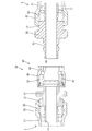
次に、本発明を具体化した実施形態3を図7及び図8を参照して説明する。本実施形態3の管継手Jcは、実施形態2のプラグ50の後端部に、ネジ部53に替えて、実施形態1と同じロック機構Lを設けたものである。このプラグ50のロック機構Lにも樹脂チューブT(図示せず)を接続することができる。その他の構成は、実施形態2と同じであるため、説明は省略する。
<Embodiment 3>
Next, a third embodiment of the present invention will be described with reference to FIGS. In the pipe joint Jc of the third embodiment, the same locking mechanism L as that of the first embodiment is provided at the rear end portion of the
<実施形態4>
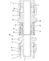
次に、本発明を具体化した実施形態4を図9を参照して説明する。本実施形態4の管継手Jdは、継手本体60の後端部に、プラグ61を、前後方向の軸線を中心として自在に回転し得るように設けたものである。継手本体60の後端部には、プラグ61を収容する円形の取付孔62が形成され、取付孔62の内周には、周方向に係止溝63が形成されている。プラグ61は、その前端部を取付孔62内に径方向のガタ付きなく且つ取付孔62の内周に摺接しつつ継手本体60に対して周方向に相対回転し得るように嵌合されている。プラグ61の外周には、取付孔62の係止溝63と対応する係止溝64が形成され、双方の係止溝63,64には略C字形の抜止リング65が係止されている。この抜止リング65の係止作用により、プラグ61は、周方向の回転は許容されるが、軸方向の変位を規制された状態で継手本体60に取り付けられている。尚、継手本体60の前端部には、実施形態と同じ構成のロック機構Lが設けられている。また、プラグ61の後端部には、ホースや樹脂チューブ(図示せず)などを接続するためのネジ部66が形成されている。
<Embodiment 4>
Next, a fourth embodiment of the present invention will be described with reference to FIG. In the pipe joint Jd of the fourth embodiment, a
<実施形態5>
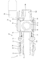
次に、本発明を具体化した実施形態5を図10ないし図12を参照して説明する。本実施形態5の管継手Jeは、前端側に実施形態1と同じ構成のロック機構Lを設けるとともに、後端側にバルブ機構70を設けたものである。以下、バルブ機構70について説明する。継手本体71の後端部には、前後方向に貫通する筒状のバルブ保持体72がねじ込みにより取り付けられている。バルブ保持体72の中心孔72Hの前端が継手本体71の中心孔71Hの後端と連通し、双方の中心孔71H,72Hによって流体の流路が構成されている。
<
Next, a fifth embodiment of the present invention will be described with reference to FIGS. The pipe joint Je of the fifth embodiment is provided with a lock mechanism L having the same configuration as that of the first embodiment on the front end side and a
バルブ保持体72には、軸線を上下方向に向けた円形の保持孔73が、バルブ保持体72を上下方向に貫通するとともに、バルブ保持体72の中心孔72Hに連通する形態で形成されている。保持孔73内には、円柱形をなす弁体74が、上下方向の軸線を中心とする回転を許容され、且つバルブ保持体72(保持孔73)に対する上下方向への相対変位を規制された状態で嵌合されている。
The
弁体74の上面には、弁体74と同心の略円形の規制板75が一体回転し得るように固着され、この規制板75の上面には、弁体74及び規制板75の中心から径方向(水平方向)に延出した形態のレバー78が、弁体74及び規制板75と一体的に回転し得るように取り付けられている。規制板75の外周には、概ね90°の角度範囲に亘って径が小さくなるように周方向に沿って切欠した形態のガイド部76が形成されている。一方、バルブ保持体72の上面には、規制ピン77が、ガイド部76と対応するように上向きに突出して設けられている。
A substantially
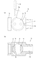
弁体74は、レバー78を摘むことにより、開弁位置と閉弁位置との間で約90°の角度範囲内で回転させることができる。開弁位置では、図11(a)に示すように、レバー78がバルブ保持体72に沿って後方へ延出するとともに、規制ピン77がガイド部76の一方の端部の係止部76aに当接することで、弁体74が閉弁方向とは逆方向(図11における時計回り方向)へ回動することが規制される。閉弁位置では、図12(a)に示すように、レバー78がバルブ保持体72から側方へ突出するとともに、規制ピン77がガイド部76の他方の端部の係止部76bに当接することで、開弁方向とは逆方向への弁体74の回動が規制される。
The
弁体74には、開弁状態において前後方向に貫通する(閉弁状態では左右方向に貫通する)円形の連通孔79が形成されている。開弁状態では、連通孔79がバルブ保持体72の中心孔72Hと連通し、これにより、管継手Jeのロック機構Lに接続された樹脂チューブ(図示せず)とバルブ保持体72の後端部外周のネジ部に固着したホースや樹脂チューブ(図示せず)との間を流体が流通できるようになる。閉弁状態では、連通孔79の両側の開口縁が共に保持孔73の内周面と対向する状態、即ち、連通孔79と中心孔72Hが連通しない(隔絶された)状態となるため、流通が不能となる。
The
弁体74の外周には、その周方向に沿ったリング状をなす上下一対のシール部材80が装着されている。このシール部材80は、連通孔79の上方位置と下方位置とに配置されて保持孔73の内周面に密着しており、この一対のシール部材80により、連通孔79内を流れる流体は、弁体74の外周と保持孔73の内周との隙間を通ってバルブ保持体72の外面側へ漏出することを規制される。
On the outer periphery of the
また、弁体74の外周には、閉弁状態においてバルブ保持体72の中心孔72Hにおける保持孔73の内周面への開口領域を包囲するリング状のシール部材81が装着されている。閉弁状態において、このシール部材81が保持孔73の内周面に密着することにより、中心孔72H内で滞留している流体は、保持孔73の内周面と弁体74の外周面との隙間を通ってバルブ保持体72の外部へ漏出することを規制される。尚、本実施形態では、このシール部材は、後部側の中心孔と対応するように配置されているが、前部側の中心孔と対応するように配置してもよい。
Further, on the outer periphery of the
<実施形態6>
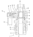
次に、本発明を具体化した実施形態6を図13及び図14を参照して説明する。本実施形態6の管継手Jfは、実施形態5においてバルブ機構を異なる構成としたものである。以下、本実施形態6のバルブ機構90について説明する。継手本体91の後端部に取り付けたバルブ保持体92内には、継手本体91の中心孔91Hとバルブ保持体92の中心孔92Hに連通する保持孔93が形成され、この保持孔93内には、略球形の弁体94が収容されている。保持孔93内には、継手本体91の中心孔91Hの後端側の開口縁を包囲するリング状のシール部材95と、バルブ保持体92の中心孔92Hの前端側の開口縁を包囲するリング状のシール部材96とが設けられ、弁体94は、その前後一対のシール部材95,96で挟まれることにより、バルブ保持体92に対して上下方向の軸を中心とする回動のみを可能に保持されている。
<Embodiment 6>
Next, a sixth embodiment of the present invention will be described with reference to FIGS. The pipe joint Jf of the sixth embodiment has a valve mechanism different from that of the fifth embodiment. Hereinafter, the valve mechanism 90 of the sixth embodiment will be described. In the
バルブ保持体92には、その上面から保持孔93に連通する軸受孔97が形成され、この軸受孔97には、回転軸98が上下方向の軸線を中心とする回転のみを可能に支持されている。この回転軸98には、レバー99が一体回転するように固着されている。かかる弁体94は、レバー99の操作により、図13に示すようにレバー99が前後方向を向く開弁位置と、図14に示すようにレバー99が開弁位置の向きに対して約90°向きを変えた閉弁位置との間で往復回動できるようになっている。
The
弁体94には、開弁状態において前後方向に貫通する(閉弁状態では左右方向に貫通する)円形の連通孔100が形成されている。開弁状態では、連通孔100が継手本体91の中心孔91H及びバルブ保持体92の中心孔92Hと連通し、これにより、管継手Jfのロック機構Lに接続された樹脂チューブ(図示せず)とバルブ保持体92の後端部外周のネジ部に固着したホース(図示せず)との間を流体が流通できるようになる。閉弁状態では、連通孔100の両側の開口縁が共に保持孔93の内周面と対向する状態、即ち、連通孔100と中心孔91H,92Hが連通しない(隔絶された)状態となるため、流通が不能となる。
The
開弁状態において、連通孔100及び中心孔91H,92Hを流れる流体は、前後一対のシール部材95,96により、弁体94の外周と保持孔93の内周との隙間へ漏出することを規制される。また、閉弁状態において、連通孔100内に残留している流体及び中心孔91H,92H内で滞留している流体は、前後一対のシール部材95,96により、弁体94の外周と保持孔93の内周との隙間へ漏出することを規制される。また、回転軸98の外周と軸受孔97の内周との隙間にはOリング101が装着されており、こりOリング101により、バルブ保持体92の外部から保持孔93内への流体の浸入が規制されている。
In the valve open state, the fluid flowing through the
<他の実施形態>
本発明は上記記述及び図面によって説明した実施形態に限定されるものではなく、例えば次のような実施態様も本発明の技術的範囲に含まれ、さらに、下記以外にも要旨を逸脱しない範囲内で種々変更して実施することができる。
<Other embodiments>
The present invention is not limited to the embodiment described with reference to the above description and drawings. For example, the following embodiments are also included in the technical scope of the present invention, and further, within the scope not departing from the gist of the invention other than the following. Various modifications can be made.
(1)上記実施形態1では締付リングの内周に溝を形成したが、本発明によれば、実施形態1において溝を形成しない形態としてもよい。 (1) Although the groove is formed on the inner periphery of the fastening ring in the first embodiment, according to the present invention, the groove may not be formed in the first embodiment.
(2)上記実施形態1において締付リングの溝を締付リングの周方向両端を除いた領域に形成したが、本発明によれば、締付リングの溝は締付リングの周方向両端に至る形態としてもよい。 (2) In Embodiment 1 above, the grooves of the tightening ring are formed in the region excluding both ends of the tightening ring in the circumferential direction. According to the present invention, the grooves of the tightening ring are formed at both ends in the circumferential direction of the tightening ring. It is good also as a form.
(3)上記実施形態1では締付リングの溝を周方向において連続する形態としたが、本発明によれば、複数の溝又は凹部を周方向に間隔を空けて配置してもよい。 (3) In Embodiment 1 described above, the grooves of the fastening ring are continuous in the circumferential direction. However, according to the present invention, a plurality of grooves or recesses may be arranged at intervals in the circumferential direction.
(4)上記実施形態1において締付リングの溝を軸線方向に間隔を空けて複数本形成してもよい。 (4) In the first embodiment, a plurality of grooves of the fastening ring may be formed at intervals in the axial direction.
(5)上記実施形態2〜6では締付リングの内周に溝を形成しない形態としたが、本発明によれば、実施形態2〜6において締付リングの内周に溝を形成してもよい。 (5) In Embodiments 2 to 6, a groove is not formed on the inner periphery of the tightening ring. However, according to the present invention, a groove is formed on the inner periphery of the tightening ring in Embodiments 2 to 6. Also good.
(6)上記実施形態では締付リングを合成樹脂製としたが、本発明によれば、締付リングを金属製としてもよい。 (6) In the above embodiment, the fastening ring is made of synthetic resin. However, according to the present invention, the fastening ring may be made of metal.
(7)上記実施形態では嵌合管の外周にテーパ状の段差を設けたが、本発明によれば、テーパ状の段差を形成しない形態としてもよい。 (7) In the above embodiment, the tapered step is provided on the outer periphery of the fitting tube. However, according to the present invention, the tapered step may not be formed.
(8)上記実施形態では嵌合管を継手本体と一体に形成したが、本発明によれば、嵌合管を継手本体とは別体部品としてもよい。 (8) In the above embodiment, the fitting tube is formed integrally with the joint body. However, according to the present invention, the fitting tube may be a separate part from the joint body.
(9)上記実施形態2、3のロックボールとプラグを用いた連結機構は、実施形態4〜6にも適用することができる。 (9) The connection mechanism using the lock ball and the plug of the second and third embodiments can be applied to the fourth to sixth embodiments.
(10)上記実施形態4のプラグを自在に回転させる構成は、実施形態5及び6にも適用できる。 (10) The configuration for freely rotating the plug of the fourth embodiment can be applied to the fifth and sixth embodiments.
(11)上記実施形態2〜6の締付リングに、実施形態1と同様の溝を形成してもよい。 (11) A groove similar to that of the first embodiment may be formed in the tightening ring of the second to sixth embodiments.
Ja…管継手
T…樹脂チューブ
10…継手本体
11…嵌合管
13…雄ネジ部
20…ロック部材
21…テーパ面
30…締付リング
Jb,Jc,Jd,Je,Jf…管継手
Ja ... pipe joint T ...
Claims (1)
嵌合管と雄ネジ部とを有する筒状の継手本体と、
内周にテーパ面を有し、前記雄ネジ部に螺合された筒状のロック部材と、
前記嵌合管との間に径方向の隙間を空けるとともに前記テーパ面と対応するように配された略C字形の締付リングとを備えてなり、
前記樹脂チューブの端末部を、前記嵌合管と前記締付リングとの間に差し込んだ状態で、前記ロック部材を螺進させて前記テーパ面の傾斜により前記締付リングを縮径変形させることで、前記樹脂チューブを締め付けて抜け規制する構成とされていることを特徴とする管継手。 To connect a tube made of synthetic resin,
A cylindrical joint body having a fitting tube and a male thread portion;
A cylindrical lock member having a tapered surface on the inner periphery and screwed to the male screw portion;
A substantially C-shaped clamping ring disposed so as to have a radial gap between the fitting tube and the tapered surface;
In a state where the end portion of the resin tube is inserted between the fitting tube and the tightening ring, the lock member is screwed to reduce the diameter of the tightening ring by the inclination of the tapered surface. The pipe joint is characterized in that the resin tube is tightened to prevent it from coming off.
Priority Applications (1)
| Application Number | Priority Date | Filing Date | Title |
|---|---|---|---|
| JP2004110367A JP2005291446A (en) | 2004-04-02 | 2004-04-02 | Pipe joint |
Applications Claiming Priority (1)
| Application Number | Priority Date | Filing Date | Title |
|---|---|---|---|
| JP2004110367A JP2005291446A (en) | 2004-04-02 | 2004-04-02 | Pipe joint |
Publications (1)
| Publication Number | Publication Date |
|---|---|
| JP2005291446A true JP2005291446A (en) | 2005-10-20 |
Family
ID=35324593
Family Applications (1)
| Application Number | Title | Priority Date | Filing Date |
|---|---|---|---|
| JP2004110367A Pending JP2005291446A (en) | 2004-04-02 | 2004-04-02 | Pipe joint |
Country Status (1)
| Country | Link |
|---|---|
| JP (1) | JP2005291446A (en) |
Cited By (3)
| Publication number | Priority date | Publication date | Assignee | Title |
|---|---|---|---|---|
| JP2012047233A (en) * | 2010-08-25 | 2012-03-08 | Daikin Industries Ltd | Pipe joint, and hot water supply device, air conditioning device and floor heating device using the same |
| JP2014114827A (en) * | 2012-12-06 | 2014-06-26 | Cosmo Koki Co Ltd | Branch pipe having valve device, and method of using the same |
| WO2020256302A1 (en) * | 2019-06-21 | 2020-12-24 | 샘찬에너지(주) | Tube fitting and assembly method therefor |
-
2004
- 2004-04-02 JP JP2004110367A patent/JP2005291446A/en active Pending
Cited By (5)
| Publication number | Priority date | Publication date | Assignee | Title |
|---|---|---|---|---|
| JP2012047233A (en) * | 2010-08-25 | 2012-03-08 | Daikin Industries Ltd | Pipe joint, and hot water supply device, air conditioning device and floor heating device using the same |
| JP2014114827A (en) * | 2012-12-06 | 2014-06-26 | Cosmo Koki Co Ltd | Branch pipe having valve device, and method of using the same |
| WO2020256302A1 (en) * | 2019-06-21 | 2020-12-24 | 샘찬에너지(주) | Tube fitting and assembly method therefor |
| KR20200145190A (en) * | 2019-06-21 | 2020-12-30 | 샘찬에너지(주) | Tube fitting and method for assembling the same |
| KR102362653B1 (en) | 2019-06-21 | 2022-02-14 | 샘찬에너지(주) | Method for assembling tube fitting |
Similar Documents
| Publication | Publication Date | Title |
|---|---|---|
| US8185984B2 (en) | Spout mounting assembly | |
| BR0300967B1 (en) | hydraulic swallowtail seal coupling having multiple radial seal surfaces. | |
| EP2563981B1 (en) | Mixing valve assembly and method of connecting supply pipes to inlets of a mixing valve | |
| JP2003232474A (en) | Pipe joint | |
| JP4145183B2 (en) | Pipe fitting | |
| JP2005291446A (en) | Pipe joint | |
| US20050280260A1 (en) | Hose connector of faucet | |
| JPH1060964A (en) | Fitting structure for water faucet hardware and cylindrical plug | |
| US7322615B1 (en) | Adjustable plumbing fitting | |
| JP2849076B2 (en) | Pipe fittings | |
| JP2005539183A (en) | Fluid quick connector for screwed fluid components | |
| JP2008106920A (en) | Pipe joint | |
| KR101642889B1 (en) | Connection device for connecting the branching pipe | |
| CN220688342U (en) | Water inlet pipe joint plugging structure of constant-temperature water mixing valve | |
| JP4909117B2 (en) | Eccentric tube and hot water mixing faucet equipped with the same | |
| JP4682078B2 (en) | Piping system manufacturing method | |
| JP2000065252A (en) | Piping structure | |
| JP2000120118A (en) | Piping device | |
| JP2007170589A (en) | Pipe fitting | |
| JP4682079B2 (en) | Piping system and manufacturing method of piping system | |
| JP2005180659A (en) | Pipe fitting | |
| JP2008101701A (en) | Connection joint for hot water pipe for panel heater | |
| JP2001254850A (en) | Ball valve | |
| JP4417648B2 (en) | Water faucet mounting structure | |
| JP2001182108A (en) | Connecting structure of piping for faucet |