JP2005291481A - Integrated valve - Google Patents

Integrated valve Download PDF

Info

Publication number
JP2005291481A
JP2005291481A JP2004111740A JP2004111740A JP2005291481A JP 2005291481 A JP2005291481 A JP 2005291481A JP 2004111740 A JP2004111740 A JP 2004111740A JP 2004111740 A JP2004111740 A JP 2004111740A JP 2005291481 A JP2005291481 A JP 2005291481A
Authority
JP
Japan
Prior art keywords
valve
port
control valve
integrated
block
Prior art date
Legal status (The legal status is an assumption and is not a legal conclusion. Google has not performed a legal analysis and makes no representation as to the accuracy of the status listed.)
Pending
Application number
JP2004111740A
Other languages
Japanese (ja)
Inventor
Kazuhiko Koike
和彦 小池
Akinori Nagaya
暁典 長屋
Current Assignee (The listed assignees may be inaccurate. Google has not performed a legal analysis and makes no representation or warranty as to the accuracy of the list.)
CKD Corp
Original Assignee
CKD Corp
Priority date (The priority date is an assumption and is not a legal conclusion. Google has not performed a legal analysis and makes no representation as to the accuracy of the date listed.)
Filing date
Publication date
Application filed by CKD Corp filed Critical CKD Corp
Priority to JP2004111740A priority Critical patent/JP2005291481A/en
Publication of JP2005291481A publication Critical patent/JP2005291481A/en
Pending legal-status Critical Current

Links

Images

Landscapes

  • Valve Housings (AREA)

Abstract

<P>PROBLEM TO BE SOLVED: To provide an integrated valve capable of reducing an installation space. <P>SOLUTION: This integrated valve has a first port 22 communicating with a first opening/closing valve 3, a second port 42 communicating with a second opening/closing valve 4, and a third port 55 communicating with the first port 22 via the first opening/closing valve 3 and communicating with the second port 42 via the second opening/closing valve 4. The integrated valve 1 switches a communicating state of the first port 22, the second port 42 and the third port 55 by controlling opening/closing valve operation of the first opening/closing valve 3 and the second opening-closing valve 4; and is provided with an installing block 2 for vertically superposing and fixing the first opening/closing valve 3 and the second opening/closing valve 4, and a connecting block 5 of opening the third port 55 for communicating an output port 23 of the first opening/closing valve 3 with an output port 43 of the second opening/closing valve 4. <P>COPYRIGHT: (C)2006,JPO&NCIPI

Description

本発明は、半導体製造工程で使用される集積弁に関する。   The present invention relates to an integrated valve used in a semiconductor manufacturing process.

従来、半導体製造装置や液晶製造装置に使用され、エッチングガスなどのプロセスガスの供給を制御するプロセスガス供給ユニットが開発されている。プロセスガス供給ユニットは、複数の流体制御機器を流路ブロックなどに固定することにより一体化される。流体制御機器には、例えば、マスフローコントローラの上流側に図10又は図11に示すような集積弁100,200が配設されている。   2. Description of the Related Art Conventionally, a process gas supply unit that is used in a semiconductor manufacturing apparatus or a liquid crystal manufacturing apparatus and controls supply of a process gas such as an etching gas has been developed. The process gas supply unit is integrated by fixing a plurality of fluid control devices to a flow path block or the like. In the fluid control device, for example, integrated valves 100 and 200 as shown in FIG. 10 or FIG. 11 are arranged upstream of the mass flow controller.

図10に示す集積弁100は、流路ブロック103,104,105,106に形成された流路が第1開閉弁101と第2開閉弁102を介して相互に連通するように集積されている。第1開閉弁101は、入力ポート101aと出力ポート101bが弁部を介して連通している。入力ポート101aは流路ブロック103を介してプロセスガス供給源に接続し、出力ポート101bは流路ブロック104を介して第2開閉弁102の入力ポート102aに連通している。第2開閉弁102は、入力ポート102aと出力ポート102bが常時連通し、出力ポート102bが流路ブロック106を介して図示しないマスフローコントローラに接続している。また、第2開閉弁102には、パージポート102cが開設され、パージポート102cと出力ポート102bが弁部を介して連通している。パージポート102cは流路ブロック105を介してパージガス供給源に接続している。   The integrated valve 100 shown in FIG. 10 is integrated so that the flow paths formed in the flow path blocks 103, 104, 105, 106 communicate with each other via the first on-off valve 101 and the second on-off valve 102. . As for the 1st on-off valve 101, the input port 101a and the output port 101b are connecting via the valve part. The input port 101 a is connected to the process gas supply source via the flow path block 103, and the output port 101 b communicates with the input port 102 a of the second on-off valve 102 via the flow path block 104. In the second on-off valve 102, the input port 102a and the output port 102b are always in communication, and the output port 102b is connected to a mass flow controller (not shown) via the flow path block 106. Further, a purge port 102c is opened in the second on-off valve 102, and the purge port 102c and the output port 102b communicate with each other via a valve portion. The purge port 102 c is connected to the purge gas supply source via the flow path block 105.

こうした集積弁100は、第1開閉弁101を開弁して第2開閉弁102を閉弁した状態で流路ブロック103にプロセスガスを供給すると、プロセスガスが流路ブロック103、第1開閉弁101、流路ブロック104、第2開閉弁102、流路ブロック106を流れてマスフローコントローラに供給される。第1開閉弁101を閉弁すると、プロセスガスの供給が停止される。また、第1開閉弁101を閉弁して第2開閉弁102を開弁した状態で流路ブロック105にパージガスを供給すると、パージガスが流路ブロック105、第2開閉弁102、流路ブロック106を流れてマスフローコントローラに供給される。   In such an integrated valve 100, when the process gas is supplied to the flow path block 103 with the first on-off valve 101 opened and the second on-off valve 102 closed, the process gas is supplied to the flow path block 103, the first on-off valve. 101, the flow path block 104, the 2nd on-off valve 102, and the flow path block 106 are supplied to a mass flow controller. When the first on-off valve 101 is closed, the supply of process gas is stopped. Further, when purge gas is supplied to the flow path block 105 with the first open / close valve 101 closed and the second open / close valve 102 opened, the purge gas flows into the flow path block 105, the second open / close valve 102, and the flow path block 106. Is supplied to the mass flow controller.

また、図11に示す集積弁200は、第1開閉弁201と第2開閉弁202が流路ブロック203,204にそれぞれ取り付けられ、流路ブロック203,204を連結することにより集積されている。流路ブロック203は、入力ポート203aと出力ポート203bとの間に弁座203cが設けられ、第1開閉弁201が弁座203cを開閉するようになっている。また、流路ブロック203は、入力ポート203aと出力ポート203bの下方にパージ流路203dが形成されている。また、流路ブロック204は、入力ポート204aと出力ポート204bが常時連通するように形成され、弁座204cと連通するようにパージ流路204dが形成されている。流路ブロック203,204は、流路ブロック203の出力ポート203bと流路ブロック204の入力ポート204aとが接続し、流路ブロック203のパージ流路203dと流路ブロック204のパージ流路204dとが接続するように連結されている。   Further, the integrated valve 200 shown in FIG. 11 is integrated by connecting the flow path blocks 203 and 204 with the first open / close valve 201 and the second open / close valve 202 being attached to the flow path blocks 203 and 204, respectively. The flow path block 203 is provided with a valve seat 203c between the input port 203a and the output port 203b, and the first on-off valve 201 opens and closes the valve seat 203c. In the flow path block 203, a purge flow path 203d is formed below the input port 203a and the output port 203b. Further, the flow path block 204 is formed so that the input port 204a and the output port 204b always communicate with each other, and a purge flow path 204d is formed so as to communicate with the valve seat 204c. The flow path blocks 203 and 204 are connected to the output port 203 b of the flow path block 203 and the input port 204 a of the flow path block 204, and the purge flow path 203 d of the flow path block 203 and the purge flow path 204 d of the flow path block 204 Are linked to connect.

こうした集積弁200は、第1開閉弁201を開弁して第2開閉弁202を閉弁した状態で流路ブロック203の入力ポート203aにプロセスガスを供給すると、プロセスガスは入力ポート203aから第1開閉弁201、出力ポート203b、流路ブロック204の入力ポート204a、第2開閉弁202、出力ポート204bへと流れ、流路ブロック204の出力ポート204bからマスフローコントローラに供給される。第1開閉弁201を閉弁すると、プロセスガスの供給が停止する。その後、第1開閉弁201を閉弁して第2開閉弁202を開弁した状態で流路ブロック203にパージガスを供給すると、パージガスが流路ブロック203のパージ流路203dから流路ブロック204のパージ流路204d、第2開閉弁202、出力ポート204bへと流れ、流路ブロック204の出力ポート204bからマスフローコントローラに供給される(例えば、特許文献1、特許文献2参照)。   When such an integrated valve 200 supplies process gas to the input port 203a of the flow path block 203 with the first on-off valve 201 opened and the second on-off valve 202 closed, the process gas is supplied from the input port 203a. The flow flows to the 1 on-off valve 201, the output port 203b, the input port 204a of the flow path block 204, the second on-off valve 202, and the output port 204b, and is supplied from the output port 204b of the flow path block 204 to the mass flow controller. When the first on-off valve 201 is closed, the supply of process gas is stopped. After that, when purge gas is supplied to the flow path block 203 with the first open / close valve 201 closed and the second open / close valve 202 opened, the purge gas flows from the purge flow path 203d of the flow path block 203 to the flow path block 204. It flows to the purge flow path 204d, the second on-off valve 202, and the output port 204b, and is supplied from the output port 204b of the flow path block 204 to the mass flow controller (see, for example, Patent Document 1 and Patent Document 2).

特開平10−148272号公報JP-A-10-148272 特開平10−311451号公報Japanese Patent Laid-Open No. 10-311451

しかしながら、従来の集積弁100,200は、いずれも第1開閉弁101,201と第2開閉弁102,202を流体の流れ方向に並設しており、設置スペースが大きかった。近年、半導体製造装置や液晶製造装置などでは装置サイズを小さくするためにプロセスガス供給ユニットをコンパクトにする要請が高く、集積弁100,200の設置スペースを小さくすることが望まれている。   However, in the conventional integrated valves 100 and 200, the first on-off valves 101 and 201 and the second on-off valves 102 and 202 are arranged side by side in the fluid flow direction, and the installation space is large. In recent years, semiconductor manufacturing apparatuses, liquid crystal manufacturing apparatuses, and the like are highly demanded to make the process gas supply unit compact in order to reduce the apparatus size, and it is desired to reduce the installation space of the integrated valves 100 and 200.

本発明は、上記問題点を解決するためになされたものであり、設置スペースを小さくできる集積弁を提供することを目的とする。   The present invention has been made to solve the above-described problems, and an object thereof is to provide an integrated valve that can reduce the installation space.

本発明に係る集積弁は、次のような構成を有している。
(1)第1制御弁と連通する第1ポートと、第2制御弁と連通する第2ポートと、第1制御弁を介して第1ポートに連通するとともに、第2制御弁を介して第2ポートに連通する第3ポートとを備え、第1制御弁と第2制御弁の開閉弁動作を制御することにより、第1ポートと第2ポートと第3ポートの連通状態を切り換える集積弁において、第1制御弁と第2制御弁とが上下に重ねて固定される取付ブロックと、第1制御弁の出力ポートと第2制御弁の出力ポートとを連通させるものであって、第3ポートが開設された連結部材とを有することを特徴とする。
The integrated valve according to the present invention has the following configuration.
(1) A first port communicating with the first control valve, a second port communicating with the second control valve, a first port via the first control valve, and a second port via the second control valve. An integrated valve that includes a third port that communicates with two ports, and switches the communication state of the first port, the second port, and the third port by controlling the opening and closing valve operations of the first control valve and the second control valve. A mounting block in which the first control valve and the second control valve are fixed one above the other, and an output port of the first control valve and an output port of the second control valve are communicated with each other, and the third port And a connecting member opened.

(2)(1)に記載の発明において、連結部材は、ブロック状をなし、第1制御弁及び第2制御弁の側方に固定され、第1制御弁の出力ポートと第2制御弁の出力ポートに連通する流路が上下方向に形成され、流路の延長線上に第3ポートが設けられていることを特徴とする。 (2) In the invention described in (1), the connecting member has a block shape and is fixed to the side of the first control valve and the second control valve, and the output port of the first control valve and the second control valve A flow path communicating with the output port is formed in the vertical direction, and a third port is provided on an extension line of the flow path.

(3)(1)又は(2)に記載の発明において、第1制御弁と第2制御弁がエアオペレイトバルブであり、取付ブロックに第1制御弁に操作流体を供給する第1操作ポートと、第2制御弁に操作流体を供給する第2操作ポートが開設され、取付ブロックが第1制御弁と第2制御弁に対して回転自在に連結していることを特徴とする。 (3) In the invention according to (1) or (2), the first control valve and the second control valve are air operated valves, and the first operation port supplies the operation fluid to the first control valve to the mounting block. And a second operation port for supplying an operation fluid to the second control valve is opened, and the mounting block is rotatably connected to the first control valve and the second control valve.

(4)(1)乃至(3)の何れか1つに記載の発明において、プロセスガス供給ユニットに対して上方から4個の締結部材で固定されることを特徴とする。 (4) In the invention according to any one of (1) to (3), the process gas supply unit is fixed by four fastening members from above.

次に、上記構成を有する発明の作用効果について説明する。
集積弁は、例えば、第1制御弁を開弁して第2制御弁を閉弁した状態で第1ポートに第1流体を供給すると、第1流体が第1制御弁の出力ポートから連結部材に流れ、第3ポートから出力される。また例えば、集積弁は、第1制御弁を閉弁して第2制御弁を開弁した状態で第2ポートに第2流体を供給すると、第2流体が第2制御弁の出力ポートから連結部材に流れ、第3ポートから出力される。こうした集積弁は、取付ブロックに第1制御弁と第2制御弁とが上下に重ねて取り付けられているため、例えば、流路ブロックに第1制御弁と第2制御弁とを並設する場合と比較して、設置スペースが小さくなる。
よって、本発明によれば、集積弁の設置スペースを小さくすることができる。
Next, the function and effect of the invention having the above configuration will be described.
For example, when the first fluid is supplied to the first port in a state where the first control valve is opened and the second control valve is closed, the integrated valve is connected to the connecting member from the output port of the first control valve. And output from the third port. Further, for example, when the integrated valve supplies the second fluid to the second port with the first control valve closed and the second control valve opened, the second fluid is connected from the output port of the second control valve. It flows to the member and is output from the third port. In such an integrated valve, the first control valve and the second control valve are attached to the mounting block so as to overlap each other. For example, when the first control valve and the second control valve are provided in parallel in the flow path block. The installation space is smaller than that.
Therefore, according to the present invention, the installation space for the integrated valve can be reduced.

ここで、連結部材をブロック形状にし、第1制御弁の出力ポートと第2制御弁の出力ポートに連通する流路が上下方向に形成され、その延長線上に第3ポートが設けられていれば、連結部材内の流路構成が簡単なので、流量損失を生じにくい。   Here, if the connecting member is formed into a block shape, a flow path communicating with the output port of the first control valve and the output port of the second control valve is formed in the vertical direction, and the third port is provided on the extension line. Since the flow path configuration in the connecting member is simple, flow rate loss is unlikely to occur.

また、第1制御弁と第2制御弁がエアオペレイトバルブである場合には、取付ブロックに開設された第1操作ポート又は第2操作ポートから第1制御弁又は第2制御弁に操作流体を供給して、第1制御弁又は第2制御弁を開閉する。取付ブロックが第1制御弁と第2制御弁に対して回転自在に連結されていれば、取付ブロックを回転させて第1操作ポートと第2操作ポートの位置を調節することができ、操作流体供給源を第1操作ポートと第2操作ポートに接続しやすい。   Further, when the first control valve and the second control valve are air operated valves, the operation fluid is transferred from the first operation port or the second operation port opened in the mounting block to the first control valve or the second control valve. To open or close the first control valve or the second control valve. If the mounting block is rotatably connected to the first control valve and the second control valve, the mounting block can be rotated to adjust the positions of the first operation port and the second operation port. It is easy to connect the supply source to the first operation port and the second operation port.

さらに、集積弁をプロセスガス供給ユニット上に配設し、上方から4個の締結部材を締結して集積弁をプロセスガス供給ユニットに固定すれば、1個の制御弁をプロセスガス供給ユニットに取り付ける作業で2個の制御弁を同時にプロセスガス供給ユニットに取り付けることができ、作業性がよい。   Further, if the integrated valve is disposed on the process gas supply unit and the four fastening members are fastened from above to fix the integrated valve to the process gas supply unit, one control valve is attached to the process gas supply unit. In operation, two control valves can be attached to the process gas supply unit at the same time, and the workability is good.

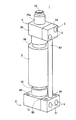
次に、本発明に係る集積弁の一実施の形態について図面を参照して説明する。図1は、集積弁1の斜視図である。
集積弁1は、例えば、半導体製造装置や液晶製造装置などに搭載されるプロセスガス供給ユニットに取り付けられ、下流に設置されるマスフローコントローラにプロセスガス又はパージガスを供給する。集積弁1は、円筒形状の取付ブロック2に対して下方から第1開閉弁(「第1制御弁」に相当するもの。)3を取り付けるとともに、上方から第2開閉弁(「第2制御弁」に相当するもの。)4を取り付け、第1開閉弁3と第2開閉弁4の側面に連結ブロック(「連結部材」に相当するもの。)を固定したものであり、あたかも1個の流体制御機器を構成するような外観を備える。
Next, an embodiment of an integrated valve according to the present invention will be described with reference to the drawings. FIG. 1 is a perspective view of the integrated valve 1.
The integrated valve 1 is attached to, for example, a process gas supply unit mounted on a semiconductor manufacturing apparatus, a liquid crystal manufacturing apparatus, or the like, and supplies process gas or purge gas to a mass flow controller installed downstream. The integrated valve 1 has a first on-off valve (corresponding to a “first control valve”) 3 attached to a cylindrical mounting block 2 from below and a second on-off valve (“second control valve” from above). 4), and a connecting block (corresponding to "connecting member") is fixed to the side surfaces of the first on-off valve 3 and the second on-off valve 4, and it is as if one fluid It has an appearance that constitutes a control device.

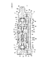
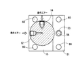
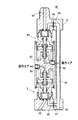
図2は、集積弁1の縦断面図である。図3は、図2のAA断面図である。
集積弁1には、取付ブロック2に第1開閉弁3と第2開閉弁4が上下逆さに重ねて取り付けられている。第1開閉弁3には第1ポート22が設けられ、第2開閉弁4には第2ポート42が設けられており、連結ブロック5を介して第1ポート22と第2ポート42が第3ポート55に連通するようになっている。
FIG. 2 is a longitudinal sectional view of the integrated valve 1. 3 is a cross-sectional view taken along the line AA in FIG.
In the integrated valve 1, a first on-off valve 3 and a second on-off valve 4 are attached to an attachment block 2 so as to be upside down. The first on-off valve 3 is provided with a first port 22, the second on-off valve 4 is provided with a second port 42, and the first port 22 and the second port 42 are connected via the connection block 5 to the third port. It communicates with the port 55.

取付ブロック2は、円柱形状をなし、第1開閉弁3を取り付けるための凹部11が下端面に穿設され、第2開閉弁4を取り付けるための凹部13が上端面に穿設されている。取付ブロック2の側面には、第1凹部11に連通する第1操作ポート12と、第2凹部13に連通する第2操作ポート14とが同一断面上に開設されている。   The mounting block 2 has a cylindrical shape, and a recess 11 for mounting the first on-off valve 3 is drilled in the lower end surface, and a recess 13 for mounting the second on-off valve 4 is drilled in the upper end surface. A first operation port 12 that communicates with the first recess 11 and a second operation port 14 that communicates with the second recess 13 are formed on the same cross section on the side surface of the mounting block 2.

第1開閉弁3は、ノーマルクローズタイプのエアオペレイトバルブである。第1開閉弁3は、ボディ15が連結フレーム16を介して取付ブロック2に図中下方から回転自在に連結されている。ボディ15は、略直方体形状のブロック状をなし、ボルト孔60,60が形成されている。ボディ15は、連結フレーム16が螺設される円柱状の連結凹部17が開設され、連結凹部17と同軸上に弁座18がかしめ固定されている。連結凹部17内には、ダイアフラム19が配設され、略円筒状のダイアフラム押さえ20を介して連結フレーム16をボディ15の連結凹部17にねじ込むことにより、ダイアフラム19の周縁部をダイアフラム押さえ20とボディ15との間で狭持している。そのため、連結フレーム16とボディ15との間に形成される空間は、ダイアフラム19によって気密に区画されて弁室21が形成されている。ボディ15には、第1ポート22が図中下端面から穿設され、出力ポート23が図中水平方向に穿設されており、第1ポート22と出力ポート23は弁座18と弁室21を介して連通している。ダイアフラム19の背室には、弁体24がダイアフラム押さえ20の内周面に沿って上下方向に摺動可能に保持され、弁体24の摺動に応じてダイアフラム19が弁座18に当接又は離間するようになっている。   The first on-off valve 3 is a normally closed type air operated valve. The first on-off valve 3 has a body 15 connected to the mounting block 2 via a connecting frame 16 so as to be rotatable from below in the figure. The body 15 has a substantially rectangular parallelepiped block shape and is formed with bolt holes 60 and 60. The body 15 has a columnar connecting recess 17 in which the connecting frame 16 is screwed, and a valve seat 18 is caulked and fixed coaxially with the connecting recess 17. A diaphragm 19 is disposed in the connecting recess 17, and the connecting frame 16 is screwed into the connecting recess 17 of the body 15 via a substantially cylindrical diaphragm presser 20, so that the peripheral portion of the diaphragm 19 is connected to the diaphragm presser 20 and the body. It is pinched between 15. Therefore, the space formed between the connecting frame 16 and the body 15 is airtightly partitioned by the diaphragm 19 to form a valve chamber 21. The body 15 has a first port 22 drilled from the lower end surface in the figure, and an output port 23 drilled in the horizontal direction in the figure. The first port 22 and the output port 23 have a valve seat 18 and a valve chamber 21. It communicates through. In the back chamber of the diaphragm 19, the valve body 24 is held so as to be slidable in the vertical direction along the inner peripheral surface of the diaphragm retainer 20, and the diaphragm 19 comes into contact with the valve seat 18 according to the sliding of the valve body 24. Alternatively, they are separated.

取付ブロック2の凹部11と連結フレーム16の間には、ピストン室26が形成され、ピストン27により一次室26Aと二次室26Bとに気密に区画されている。一次室26Aには、圧縮ばね30が縮設され、ピストン27を常時図中Y方向に付勢している。ピストン27には、ピストンロッド28が貫き通されて一体化されている。ピストンロッド28は、先端部が連結フレーム16を貫いて弁体24に突き当てられ、弁体24を介してダイアフラム19を図中Y方向にに押し下げて弁座18に当接させている。ピストンロッド28には、第1操作ポート12に供給された操作エアを二次室26Bに供給するための流路29が形成されている。従って、一次室26Aと二次室26Bの圧力変動を制御することにより、ピストン27を図中X方向又はY方向に移動させ、ダイアフラム19を弁座18に当接又は離間させることが可能である。   A piston chamber 26 is formed between the recess 11 of the mounting block 2 and the connecting frame 16, and the piston 27 is hermetically partitioned into a primary chamber 26 </ b> A and a secondary chamber 26 </ b> B. A compression spring 30 is contracted in the primary chamber 26A, and the piston 27 is always urged in the Y direction in the drawing. A piston rod 28 is passed through and integrated with the piston 27. The tip of the piston rod 28 penetrates the connecting frame 16 and is abutted against the valve body 24, and the diaphragm 19 is pushed down in the Y direction through the valve body 24 to contact the valve seat 18. The piston rod 28 is formed with a flow path 29 for supplying the operation air supplied to the first operation port 12 to the secondary chamber 26B. Therefore, by controlling the pressure fluctuations in the primary chamber 26A and the secondary chamber 26B, it is possible to move the piston 27 in the X direction or the Y direction in the drawing and to bring the diaphragm 19 into contact with or away from the valve seat 18. .

一方、第2開閉弁4は、ノーマルオープンタイプのエアオペレイトバルブである。第2開閉弁4は、ボディ35が連結フレーム36を介して取付ブロック2に図中上方から回転自在に連結されている。ボディ35は、略直方体形状のブロック状をなし、第2開閉弁4側から第1開閉弁3のボルト孔60,60が見えるように第1開閉弁3のボディ15より幅が小さく設定されている。ボディ35は、連結フレーム36が螺設される円柱状の連結凹部37が開設され、連結凹部37と同軸上に弁座38がかしめ固定されている。連結凹部37内には、ダイフラム39が配設され、略円筒状のダイアフラム押さえ40を介して連結フレーム36をボディ35の連結凹部37にねじ込むことにより、ダイアフラム39の周縁部をダイアフラム押さえ40とボディ35との間で狭持している。そのため、連結フレーム36とボディ35との間に形成される空間は、ダイアフラム39によって気密に区画されて弁室41が形成されている。ボディ35には、弁座38と同軸上に継手35aが図中突設されて第2ポート42が設けられ、出力ポート43が図中水平方向に穿設されており、第2ポート42と出力ポート43は弁座38と弁室41を介して連通している。ダイアフラム39の背室には、弁体44がダイアフラム押さえ40の内周面に沿って上下方向に摺動可能に保持され、弁体44の摺動に応じてダイアフラム39が弁座38に当接又は離間するようになっている。   On the other hand, the second on-off valve 4 is a normally open type air operated valve. The second opening / closing valve 4 has a body 35 connected to the mounting block 2 via a connecting frame 36 so as to be rotatable from above in the figure. The body 35 has a substantially rectangular parallelepiped block shape, and the width is set smaller than the body 15 of the first on-off valve 3 so that the bolt holes 60, 60 of the first on-off valve 3 can be seen from the second on-off valve 4 side. Yes. The body 35 is provided with a columnar connecting recess 37 into which the connecting frame 36 is screwed, and a valve seat 38 is caulked and fixed coaxially with the connecting recess 37. A diaphragm 39 is disposed in the coupling recess 37, and the coupling frame 36 is screwed into the coupling recess 37 of the body 35 via the substantially cylindrical diaphragm retainer 40, so that the peripheral portion of the diaphragm 39 is connected to the diaphragm retainer 40 and the body. 35. Therefore, the space formed between the connection frame 36 and the body 35 is airtightly partitioned by the diaphragm 39 to form the valve chamber 41. In the body 35, a joint 35a is provided on the same axis as the valve seat 38, and a second port 42 is provided, and an output port 43 is formed in the horizontal direction in the figure. The port 43 communicates with the valve seat 38 via the valve chamber 41. The valve body 44 is held in the back chamber of the diaphragm 39 so as to be slidable in the vertical direction along the inner peripheral surface of the diaphragm retainer 40, and the diaphragm 39 contacts the valve seat 38 according to the sliding of the valve body 44. Alternatively, they are separated.

取付ブロック2の凹部13と連結フレーム36の間には、ピストン室46が形成され、ピストン47により一次室46Aと二次室46Bとに気密に区画されている。二次室46Bには、圧縮ばね50が縮設され、ピストン47を常時図中Y方向に付勢している。ピストン47には、ピストンロッド48が貫き通されて一体化されている。ピストンロッド48は、先端部が連結フレーム36を貫くものの、図中Y方向に下降しているため、弁体44を介してダイアフラム39を図中X方向に押し上げず、ダイアフラム39が弁座38から離間している。従って、一次室46Aと二次室26Bの圧力変動を制御することにより、ピストン47を図中X方向又は図中Y方向に移動させ、ダイアフラム39を弁座38に当接又は離間させることが可能である。   A piston chamber 46 is formed between the recess 13 of the mounting block 2 and the connecting frame 36, and the piston 47 is partitioned into a primary chamber 46 </ b> A and a secondary chamber 46 </ b> B in an airtight manner. A compression spring 50 is contracted in the secondary chamber 46B, and the piston 47 is always urged in the Y direction in the drawing. A piston rod 48 is passed through and integrated with the piston 47. The piston rod 48 passes through the connecting frame 36 at the tip, but is lowered in the Y direction in the figure. Therefore, the diaphragm 39 is not pushed up in the X direction in the figure via the valve body 44, and the diaphragm 39 moves from the valve seat 38. It is separated. Therefore, by controlling the pressure fluctuations in the primary chamber 46A and the secondary chamber 26B, the piston 47 can be moved in the X direction in the figure or the Y direction in the figure, and the diaphragm 39 can be brought into contact with or separated from the valve seat 38. It is.

第1開閉弁3のボディ15と第2開閉弁4のボディ35には、連結ブロック5が側方から固定され、第1開閉弁3の出力ポート23と第2開閉弁4の出力ポート43とを第3ポート55に連通させている。連結ブロック5は、直方体形状の第1ブロック51と直方体形状の第2ブロック52とをパイプ53で連結した形状を有し、第3ポート55が第1ブロック51の下端面から穿設されている。連結ブロック5は、第3ポート55と同軸上に共通流路56が図中上下方向に形成され、共通流路56に対して直交するように第1連通路57と第2連通路58が形成されている。第1連通路57は、第1ブロック51の第1開閉弁3に当接する側面に第1開閉弁3の出力ポート23と接続するように形成されている。また、第2連通路58は、第2ブロック52の第2開閉弁4に当接する側面に第2開閉弁4の出力ポート43と接続するように形成されている。   A connecting block 5 is fixed to the body 15 of the first on-off valve 3 and the body 35 of the second on-off valve 4 from the side, and the output port 23 of the first on-off valve 3 and the output port 43 of the second on-off valve 4 Is communicated with the third port 55. The connection block 5 has a shape in which a rectangular parallelepiped first block 51 and a rectangular parallelepiped second block 52 are connected by a pipe 53, and a third port 55 is formed from the lower end surface of the first block 51. . In the connection block 5, a common flow path 56 is formed on the same axis as the third port 55 in the vertical direction in the figure, and a first communication path 57 and a second communication path 58 are formed so as to be orthogonal to the common flow path 56. Has been. The first communication passage 57 is formed on the side surface of the first block 51 that contacts the first opening / closing valve 3 so as to be connected to the output port 23 of the first opening / closing valve 3. The second communication passage 58 is formed on the side surface of the second block 52 that contacts the second opening / closing valve 4 so as to be connected to the output port 43 of the second opening / closing valve 4.

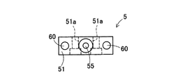
図4は、連結ブロック5の正面図である。図5は、連結ブロック5の下面図である。
連結ブロック5は、第1ブロック51が第2ブロック52より幅が大きく設定され、ボルト孔60が第2ブロック52側から見えるように第1ブロック51に形成されている。第1ブロック51は、第1連通路57の両側にボルト孔51a,51aが形成され、第2ブロック52には、第2連通録58の両側にボルト孔52a,52aが形成されている。そのため、第1開閉弁3の出力ポート23と連結ブロック5の第1連通路57との間、及び、第2開閉弁4の出力ポート43と連結ブロック5の第2連通路58との間にOリングなどのシール部材(図示せず)をそれぞれ配設し、第1ブロック51のボルト孔51a,51aと第2ブロック52のボルト孔52a,52aに挿通したボルトV…(図1参照)を第1開閉弁3のボディ15と第2開閉弁4のボディ35にねじ込んで連結ブロック5を固定するときに、シール性が確保される。
FIG. 4 is a front view of the connecting block 5. FIG. 5 is a bottom view of the connecting block 5.
The connecting block 5 is formed in the first block 51 so that the first block 51 is set to be wider than the second block 52 and the bolt hole 60 is visible from the second block 52 side. Bolt holes 51 a and 51 a are formed on both sides of the first communication path 57 in the first block 51, and bolt holes 52 a and 52 a are formed on both sides of the second continuous recording 58 in the second block 52. Therefore, between the output port 23 of the first on-off valve 3 and the first communication passage 57 of the connection block 5 and between the output port 43 of the second on-off valve 4 and the second communication passage 58 of the connection block 5. Seal members (not shown) such as O-rings are disposed, and bolts V ... (see FIG. 1) inserted through the bolt holes 51a, 51a of the first block 51 and the bolt holes 52a, 52a of the second block 52, respectively. When the connecting block 5 is fixed by screwing into the body 15 of the first on-off valve 3 and the body 35 of the second on-off valve 4, sealing performance is ensured.

次に、上記構成を有する本実施の形態の集積弁1の作用について説明する。
集積弁1は、プロセスガス供給ユニットのマスフローコントローラの上流に配置され、4隅に設けられたボルト孔60,60,60,60(図1参照)に図示しないボルトを第2開閉弁4側から挿通して図示しないプロセスガス供給ユニットにねじ込むことにより固定される。このとき、ボルト孔60,60,60,60が第2開閉弁4側から見えるため、ボルトを締結しやすい。これにより、集積弁1は、第1ポート22が図示しないプロセスガス供給源に連通し、第3ポート55が図示しないマスフローコントローラに連通する。そして、第2開閉弁4の継手35aにパージガス供給源を接続することにより、第2ポート42がパージガス供給源に連通する。集積弁1は、第2開閉弁4の継手35aが上向きに突き出しているので、隣り合う流体制御機器との隙間が狭い場合でも、パージガス供給源を接続できる。それから、第1操作ポート12と第2操作ポート14に図示しない操作エア供給源を接続する。このとき、取付ブロック2を第1開閉弁3と第2開閉弁4に対して自由に回転させて第1操作ポート12と第2操作ポート14の位置を調節できるため、第1,第2操作ポート12,14に図示しない操作エア供給源を接続しやすい。
Next, the operation of the integrated valve 1 of the present embodiment having the above configuration will be described.
The integrated valve 1 is disposed upstream of the mass flow controller of the process gas supply unit, and bolts (not shown) are provided in bolt holes 60, 60, 60, 60 (see FIG. 1) provided at the four corners from the second opening / closing valve 4 side. It is fixed by being inserted and screwed into a process gas supply unit (not shown). At this time, since the bolt holes 60, 60, 60, 60 are visible from the second on-off valve 4 side, it is easy to fasten the bolt. Thus, in the integrated valve 1, the first port 22 communicates with a process gas supply source (not shown), and the third port 55 communicates with a mass flow controller (not shown). Then, by connecting a purge gas supply source to the joint 35a of the second on-off valve 4, the second port 42 communicates with the purge gas supply source. Since the joint 35a of the second on-off valve 4 protrudes upward in the integrated valve 1, the purge gas supply source can be connected even when the gap between the adjacent fluid control devices is narrow. Then, an operation air supply source (not shown) is connected to the first operation port 12 and the second operation port 14. At this time, the mounting block 2 can be freely rotated with respect to the first on-off valve 3 and the second on-off valve 4 so that the positions of the first operation port 12 and the second operation port 14 can be adjusted. It is easy to connect an operating air supply source (not shown) to the ports 12 and 14.

集積弁1は、第1操作ポート12と第2操作ポート14に操作エアが供給されないときには、第1開閉弁3が閉弁し、第2開閉弁4が開弁している。この状態を初期状態として説明する。   In the integrated valve 1, when the operation air is not supplied to the first operation port 12 and the second operation port 14, the first on-off valve 3 is closed and the second on-off valve 4 is opened. This state will be described as an initial state.

プロセスガスを図示しないマスフローコントローラに供給する場合には、第1操作ポート12と第2操作ポート14に操作エアを供給する。第2開閉弁4は、一次室46Aが加圧されて、ピストン47が圧縮ばね50に抗して図中X方向に上昇する。ピストンロッド48は、ピストン47と一体的に図中X方向に上昇して弁体44を弁座38側に押し上げ、ダイアフラム39を弁座38に当接させる。これにより、第2開閉弁4が閉弁する。
一方、第1開閉弁3は、操作エアがピストンロッド28の連通路29から二次室26Bに供給され、二次室26Bが加圧される。ピストン27は、圧縮ばね30に抗して図中X方向に上昇し、弁体24から離間する。第1ポート22にプロセスガスを供給すると、ダイアフラム19がプロセスガスの圧力によって弁体24を図中X方向に押し上げ、弁座18から離間する。これにより、第1開閉弁3が開弁する。
When supplying process gas to a mass flow controller (not shown), operation air is supplied to the first operation port 12 and the second operation port 14. In the second on-off valve 4, the primary chamber 46A is pressurized, and the piston 47 rises in the X direction in the figure against the compression spring 50. The piston rod 48 rises integrally with the piston 47 in the X direction in the drawing, pushes up the valve body 44 toward the valve seat 38, and brings the diaphragm 39 into contact with the valve seat 38. Thereby, the 2nd on-off valve 4 closes.
On the other hand, in the first on-off valve 3, operating air is supplied from the communication passage 29 of the piston rod 28 to the secondary chamber 26B, and the secondary chamber 26B is pressurized. The piston 27 rises in the X direction in the figure against the compression spring 30 and is separated from the valve body 24. When the process gas is supplied to the first port 22, the diaphragm 19 pushes up the valve body 24 in the X direction in the drawing by the pressure of the process gas, and moves away from the valve seat 18. Thereby, the 1st on-off valve 3 opens.

第1ポート22に供給されたプロセスガスは、第1ポート22から弁座18、弁室21、出力ポート23、連結ブロック5の第1連通路57、第3ポート55へと流れ、第3ポート55から図示しないマスフローコントローラに供給される。このとき、プロセスガスは、ガスの流れに沿って連結ブロック5の第1連通路57から第3ポート55に引き込まれるが、たとえ、プロセスガスの一部が連結ブロック5の共通流路56内に拡散しても、第2開閉弁4が閉弁しているため、第2開閉弁4の弁座38から第2ポート42に逆流しない。   The process gas supplied to the first port 22 flows from the first port 22 to the valve seat 18, the valve chamber 21, the output port 23, the first communication path 57 of the connection block 5, and the third port 55. 55 is supplied to a mass flow controller (not shown). At this time, the process gas is drawn into the third port 55 from the first communication path 57 of the connection block 5 along the gas flow. For example, a part of the process gas enters the common flow path 56 of the connection block 5. Even if it diffuses, since the second on-off valve 4 is closed, it does not flow backward from the valve seat 38 of the second on-off valve 4 to the second port 42.

その後、プロセスガスの供給を停止する場合には、第1操作ポート12への操作エアの供給を停止する。第1開閉弁3は、二次室26Bが加圧されなくなり、ピストン27が圧縮ばね30の弾圧力で図中Y方向に押し下げられる。ピストンロッド28は、ピストン27と一体的に図中Y方向に下降して弁体24を弁座18側に押し下げ、ダイアフラム19を弁座18に当接させる。これにより、第1開閉弁3が閉弁し、プロセスガスが第1開閉弁3から供給されなくなる。   Thereafter, when the supply of process gas is stopped, the supply of operation air to the first operation port 12 is stopped. In the first on-off valve 3, the secondary chamber 26 </ b> B is no longer pressurized, and the piston 27 is pushed down in the Y direction in the figure by the elastic force of the compression spring 30. The piston rod 28 is lowered integrally with the piston 27 in the Y direction in the drawing to push down the valve body 24 toward the valve seat 18, thereby bringing the diaphragm 19 into contact with the valve seat 18. Thereby, the first on-off valve 3 is closed, and the process gas is not supplied from the first on-off valve 3.

その後、パージガスをマスフローコントローラに供給する場合には、第2操作ポート14への操作エアの供給を停止する。第2開閉弁4は、一次室46Aが加圧されなくなり、ピストン47が圧縮ばね50の弾圧力で図中Y方向に押し下げられる。ピストンロッド48は、ピストン47と一体的に図中Y方向に下降して弁体44を押し上げなくなる。弁体44は、自重によって図中Y方向に移動し、ダイアフラム39が弁座38から離間する。これにより、第2開閉弁4が開弁する。   Thereafter, when the purge gas is supplied to the mass flow controller, the supply of the operation air to the second operation port 14 is stopped. In the second on-off valve 4, the primary chamber 46 </ b> A is not pressurized, and the piston 47 is pushed down in the Y direction in the figure by the elastic force of the compression spring 50. The piston rod 48 is lowered integrally with the piston 47 in the Y direction in the figure and does not push up the valve body 44. The valve body 44 moves in the Y direction in the figure by its own weight, and the diaphragm 39 is separated from the valve seat 38. Thereby, the 2nd on-off valve 4 opens.

第2ポート42に供給されたパージガスは、第2ポート42から弁座38、弁室41、出力ポート43、連結ブロック5の第1連通路58、共通流路56、第3ポート55へと流れ、第3ポート55からマスフローコントローラに供給される。このとき、第1開閉弁3が閉弁しているため、パージガスが第1開閉弁3の弁座18から第1ポート22に逆流しない。
なお、この状態でパージガスの供給を停止すると、集積弁1は初期状態に戻る。
The purge gas supplied to the second port 42 flows from the second port 42 to the valve seat 38, the valve chamber 41, the output port 43, the first communication path 58 of the connection block 5, the common flow path 56, and the third port 55. , And supplied from the third port 55 to the mass flow controller. At this time, since the first on-off valve 3 is closed, the purge gas does not flow backward from the valve seat 18 of the first on-off valve 3 to the first port 22.
If the supply of purge gas is stopped in this state, the accumulation valve 1 returns to the initial state.

従って、本実施の形態の集積弁1によれば、第1開閉弁3と連通する第1ポート22と、第2開閉弁4と連通する第2ポート42と、第1開閉弁3を介して第1ポート22に連通するとともに、第2開閉弁4を介して第2ポート42に連通する第3ポート55とを備え、第1開閉弁3と第2開閉弁4の開閉弁動作を制御することにより、第1ポート22と第2ポート42と第3ポート55の連通状態を切り換えるものであって、第1開閉弁3と第2開閉弁4とが上下に重ねて固定される取付ブロック2と、第1開閉弁3の出力ポート23と第2開閉弁4の出力ポート43とを連通させるものであって、第3ポート55が開設された連結ブロック5とを有しているので、例えば、流路ブロックに第1開閉弁と第2開閉弁とを並設する場合(例えば、図10、図11参照)と比較して、設置スペースを小さくすることができる。ここで、集積弁1は、連結ブロック5を第1開閉弁3と第2開閉弁4の側面に固定する。しかし、連結ブロック5が一般的な開閉弁より小さいため、集積弁1は2個の開閉弁を平面に並設する場合より設置スペースが小さくなる。   Therefore, according to the integrated valve 1 of the present embodiment, the first port 22 that communicates with the first on-off valve 3, the second port 42 that communicates with the second on-off valve 4, and the first on-off valve 3. A third port 55 communicates with the first port 22 and communicates with the second port 42 via the second on-off valve 4, and controls the on-off valve operations of the first on-off valve 3 and the second on-off valve 4. Accordingly, the communication state of the first port 22, the second port 42, and the third port 55 is switched, and the first on-off valve 3 and the second on-off valve 4 are fixed in a vertically stacked manner. And the output port 23 of the first on-off valve 3 and the output port 43 of the second on-off valve 4, and the connecting port 5 having the third port 55 opened. When the first on-off valve and the second on-off valve are arranged in parallel in the flow path block (for example, Can be compared 10, see FIG. 11) and to reduce the installation space. Here, the integrated valve 1 fixes the connecting block 5 to the side surfaces of the first on-off valve 3 and the second on-off valve 4. However, since the connecting block 5 is smaller than a general on-off valve, the integrated valve 1 has a smaller installation space than a case where two on-off valves are arranged side by side.

また、本実施の形態の集積弁1によれば、連結ブロック5は、ブロック状をなし、第1開閉弁3及び第2開閉弁4の側方に固定され、第1開閉弁3の出力ポート23と第2開閉弁4の出力ポート43に連通する共通流路56が上下方向に形成され、共通流路56の延長線上に第3ポート55が設けられているので、連結ブロック5内の流路構成が簡単であり、流量損失を生じにくい。   Further, according to the integrated valve 1 of the present embodiment, the connecting block 5 has a block shape, is fixed to the side of the first on-off valve 3 and the second on-off valve 4, and the output port of the first on-off valve 3 23 and the output port 43 of the second on-off valve 4 are formed in the vertical direction, and the third port 55 is provided on the extended line of the common flow channel 56. The path configuration is simple and it is difficult for flow loss to occur.

また、本実施の形態の集積弁1によれば、第1開閉弁3と第2開閉弁4がエアオペレイトバルブであり、取付ブロック2に第1開閉弁3に操作エアを供給する第1操作ポート12と、第2開閉弁4に操作流体を供給する第2操作ポート14が開設され、取付ブロック2が第1開閉弁3と第2開閉弁4に対して回転自在に連結しているので、取付ブロック2を回転させて第1操作ポート12と第2操作ポート14の位置を調節することができ、図示しない操作エア供給源を第1操作ポート12と第2操作ポート14に接続しやすい。   Further, according to the integrated valve 1 of the present embodiment, the first on-off valve 3 and the second on-off valve 4 are air operated valves, and the first on-off operating air is supplied to the first on-off valve 3 to the mounting block 2. An operation port 12 and a second operation port 14 for supplying an operation fluid to the second on-off valve 4 are opened, and the mounting block 2 is rotatably connected to the first on-off valve 3 and the second on-off valve 4. Therefore, the mounting block 2 can be rotated to adjust the positions of the first operation port 12 and the second operation port 14, and an operation air supply source (not shown) is connected to the first operation port 12 and the second operation port 14. Cheap.

また、本実施の形態の集積弁1によれば、図示しないプロセスガス供給ユニットに対して上方から4個のボルトで固定されるので、1個の開閉弁をプロセスガス供給ユニットに取り付ける作業で2個の開閉弁を同時にプロセスガス供給ユニットに取り付けることができ、作業性がよい。   Further, according to the integrated valve 1 of the present embodiment, since it is fixed to the process gas supply unit (not shown) by four bolts from above, the operation of attaching one on-off valve to the process gas supply unit 2 The on-off valves can be attached to the process gas supply unit at the same time, and the workability is good.

尚、本発明の実施の形態について説明したが、本発明は、上記実施の形態に限定されることなく、色々な応用が可能である。   Although the embodiments of the present invention have been described, the present invention is not limited to the above-described embodiments, and various applications are possible.

(1)例えば、上記実施の形態では、取付ブロック2の同一断面上に90度の位相差をもって第1操作ポート12と第2操作ポート14を開設した。これに対して、図6の第1変形例に示すように、取付ブロック62に第1操作ポート63と第2操作ポート64を高さを変えて開設し、同一断面上に設けないようにしてもよいし、また、図6の第1変形例及び図7の第2変形例に示すように、第1操作ポート63,73と第2操作ポート64,74を90度でない位相差(例えば、180度)をもって開設してもよい。 (1) For example, in the above embodiment, the first operation port 12 and the second operation port 14 are opened with a phase difference of 90 degrees on the same cross section of the mounting block 2. On the other hand, as shown in the first modification of FIG. 6, the first operation port 63 and the second operation port 64 are opened in the mounting block 62 at different heights so that they are not provided on the same cross section. Alternatively, as shown in the first modification example in FIG. 6 and the second modification example in FIG. 7, the first operation ports 63 and 73 and the second operation ports 64 and 74 have a phase difference that is not 90 degrees (for example, 180 degrees).

(2)例えば、上記実施の形態では、取付ブロック2にノーマルクローズタイプの第1開閉弁3とノーマルオープンタイプの第2開閉弁4とを上下逆さに重ねて取り付けた。これに対して、第1開閉弁3と第2開閉弁4の向きを揃えて上下に重ねて取り付けても良い。また、図6の第1変形例に示すように、ノーマルクローズタイプの第1開閉弁3と第2開閉弁65を上下に重ねて取り付けるようにしてよい。なお、この場合には、上記実施の形態で説明した第2開閉弁4のアクチュエータ部を、第1開閉弁3のアクチュエータ部と同様の構造として第2開閉弁65を構成するようにしてもよい。また、図7の第2変形例に示すように、ノーマルオープンタイプの第1開閉弁75と第2開閉弁4を上下に重ねて取り付けるようにしてよい。なお、この場合には、上記実施の形態の第1開閉弁3のアクチュエータ部を、第2開閉弁4のアクチュエータ部と同様の構造として第1開閉弁75を構成するようにしてもよい。 (2) For example, in the above embodiment, the normally closed type first on-off valve 3 and the normally open type second on-off valve 4 are attached to the mounting block 2 so as to be upside down. On the other hand, the first opening / closing valve 3 and the second opening / closing valve 4 may be aligned in the vertical direction and attached. In addition, as shown in the first modification of FIG. 6, the first on-off valve 3 and the second on-off valve 65 of the normal close type may be attached to overlap each other. In this case, the second opening / closing valve 65 may be configured with the actuator portion of the second opening / closing valve 4 described in the above embodiment having the same structure as the actuator portion of the first opening / closing valve 3. . Further, as shown in the second modification of FIG. 7, the first open / close valve 75 and the second open / close valve 4 of the normal open type may be attached so as to overlap each other. In this case, the first on-off valve 75 may be configured with the actuator portion of the first on-off valve 3 of the above embodiment having the same structure as the actuator portion of the second on-off valve 4.

(3)例えば、上記実施の形態では、第2開閉弁4のボディ35に継手35aを上方に突き出すように突設した。これに対して、例えば、図8の第3変形例に示すように、第2開閉弁4のボディ35の側面に継手82を突設して第2ポート83を設け、第2ポート83と出力ポート43を弁座38を介して連通させるようにしてもよい。 (3) For example, in the above-described embodiment, the joint 35a protrudes upward from the body 35 of the second on-off valve 4. On the other hand, for example, as shown in a third modification of FIG. 8, a second port 83 is provided by projecting a joint 82 on the side surface of the body 35 of the second on-off valve 4, and the second port 83 and the output The port 43 may be communicated with the valve seat 38.

(4)例えば、上記実施の形態では、第1ポート22を下方に開口するように形成した。これに対して、例えば、図9の第4変形例に示すように、第1開閉弁3のボディ15の側面に継手92を突設して第1ポート93を設け、第1ポート93と出力ポート23を弁座18を介して連通させるようにしてもよい。 (4) For example, in the above embodiment, the first port 22 is formed to open downward. On the other hand, for example, as shown in a fourth modified example of FIG. 9, a first port 93 is provided by projecting a joint 92 on the side surface of the body 15 of the first on-off valve 3. The port 23 may be communicated with the valve seat 18.

(5)例えば、上記実施の形態では、第3ポート55を下方に開口するように形成した。これに対して、例えば、図9の第4変形例に示すように、連結ブロック5の第1ブロック51の側面に継手95を突設して第3ポート96を設け、連結ブロック5の共通流路56と連通させるようにしてもよい。 (5) For example, in the above embodiment, the third port 55 is formed to open downward. On the other hand, for example, as shown in a fourth modified example of FIG. 9, a joint 95 is provided on the side surface of the first block 51 of the connection block 5 to provide a third port 96. You may make it connect with the path | route 56. FIG.

(6)例えば、上記実施の形態では、第1開閉弁3と第2開閉弁4にエアオペレイトバルブを使用したが、第1開閉弁又は第2開閉弁に電磁式のものを使用してもよい。また、例えば、上記実施の形態では、第1開閉弁3と第2開閉弁4にダイアフラム弁を使用したが、ベローズ弁を使用してもよい。
(7)例えば、上記実施の形態では、第1ポート22又は第2ポート43に供給したガスを第3ポート55から出力するが、第3ポート55に供給したガスを第1ポート22と第2ポート43から分岐して出力するようにしてもよい。この場合には、第1開閉弁3と第2開閉弁4を比例弁にして、所定の分流比で流体を出力するようにしてもよい。
(8)例えば、上記実施の形態では、半導体製造装置や液晶製造装置に搭載されるプロセスガス供給ユニットに集積弁1を取り付けたが、複数の液又はガスを切り換えて出力するものであれば、流体の種類や使用用途はこれに限定されるものではない。
(6) For example, in the above embodiment, air operated valves are used for the first on-off valve 3 and the second on-off valve 4, but electromagnetic ones are used for the first on-off valve or the second on-off valve. Also good. For example, in the said embodiment, although the diaphragm valve was used for the 1st on-off valve 3 and the 2nd on-off valve 4, you may use a bellows valve.
(7) For example, in the above embodiment, the gas supplied to the first port 22 or the second port 43 is output from the third port 55, but the gas supplied to the third port 55 is output from the first port 22 and the second port 55. The output may be branched from the port 43 and output. In this case, the first on-off valve 3 and the second on-off valve 4 may be proportional valves to output fluid at a predetermined diversion ratio.
(8) For example, in the above embodiment, the integrated valve 1 is attached to a process gas supply unit mounted on a semiconductor manufacturing apparatus or a liquid crystal manufacturing apparatus, but if a plurality of liquids or gases are switched and output, The type of fluid and the intended use are not limited to this.

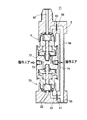
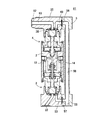
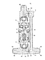
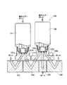
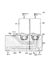
本発明の実施の形態に係り、集積弁の斜視図である。1 is a perspective view of an integrated valve according to an embodiment of the present invention. 同じく、集積弁の縦断面図である。Similarly, it is a longitudinal sectional view of the integrated valve. 同じく、図2のAA断面図である。Similarly, it is AA sectional drawing of FIG. 同じく、連結ブロックの正面図である。Similarly, it is a front view of a connection block. 同じく、連結ブロックの下面図である。Similarly, it is a bottom view of a connection block. 本発明の集積弁の第1変形例である。It is a 1st modification of the integrated valve of this invention. 本発明の集積弁の第2変形例である。It is a 2nd modification of the integrated valve of this invention. 本発明の集積弁の第3変形例である。It is a 3rd modification of the integrated valve of this invention. 本発明の集積弁の第4変形例である。It is a 4th modification of the integrated valve of this invention. 従来のガス又は液体集積弁の構造を示す図である。It is a figure which shows the structure of the conventional gas or liquid accumulation | storage valve. 従来のガス又は液体集積弁の構造を示す図である。It is a figure which shows the structure of the conventional gas or liquid accumulation | storage valve.

符号の説明Explanation of symbols

1 集積弁
2 取付ブロック
3 第1開閉弁
4 第2開閉弁
5 連結ブロック
12 第1操作ポート
14 第2操作ポート
22 第1ポート
23 出力ポート
42 第2ポート
43 出力ポート
55 第3ポート
56 共通流路
61 集積弁
62 取付ブロック
63 第1操作ポート
64 第2操作ポート
65 第2開閉弁
71 集積弁
72 取付ブロック
75 第1開閉弁
81 集積弁
82 継手
83 第2ポート
91 集積弁
92 継手
93 第1ポート
95 継手
96 第3ポート
DESCRIPTION OF SYMBOLS 1 Integrated valve 2 Mounting block 3 1st on-off valve 4 2nd on-off valve 5 Connection block 12 1st operation port 14 2nd operation port 22 1st port 23 Output port 42 2nd port 43 Output port 55 3rd port 56 Common flow Path 61 Integrated valve 62 Mounting block 63 First operation port 64 Second operation port 65 Second on-off valve 71 Integrated valve 72 Mounting block 75 First on-off valve 81 Integrated valve 82 Joint 83 Second port 91 Integrated valve 92 Joint 93 First Port 95 Joint 96 3rd port

Claims (4)

第1制御弁と連通する第1ポートと、第2制御弁と連通する第2ポートと、前記第1制御弁を介して第1ポートに連通するとともに、前記第2制御弁を介して前記第2ポートに連通する第3ポートとを備え、前記第1制御弁と前記第2制御弁の開閉弁動作を制御することにより、前記第1ポートと前記第2ポートと前記第3ポートの連通状態を切り換える集積弁において、
前記第1制御弁と前記第2制御弁とが上下に重ねて固定される取付ブロックと、
前記第1制御弁の出力ポートと前記第2制御弁の出力ポートとを連通させるものであって、前記第3ポートが開設された連結部材とを有することを特徴とする集積弁。
A first port that communicates with the first control valve, a second port that communicates with the second control valve, and communicates with the first port via the first control valve, and the second port via the second control valve. A third port communicating with the two ports, and controlling the opening and closing valve operations of the first control valve and the second control valve, thereby communicating the first port, the second port, and the third port. In the integrated valve that switches between
A mounting block on which the first control valve and the second control valve are fixed in an overlapping manner;
An integrated valve characterized in that the output port of the first control valve and the output port of the second control valve are communicated with each other and a connecting member having the third port opened.
請求項1に記載する集積弁において、
前記連結部材は、ブロック状をなし、前記第1制御弁及び前記第2制御弁の側方に固定され、前記第1制御弁の出力ポートと前記第2制御弁の出力ポートに連通する流路が上下方向に形成され、前記流路の延長線上に第3ポートが設けられていることを特徴とする集積弁。
The integrated valve according to claim 1,
The connecting member has a block shape, is fixed to a side of the first control valve and the second control valve, and communicates with an output port of the first control valve and an output port of the second control valve. Is formed in the vertical direction, and a third port is provided on an extension line of the flow path.
請求項1又は請求項2に記載する集積弁において、
前記第1制御弁と前記第2制御弁がエアオペレイトバルブであり、
前記取付ブロックに前記第1制御弁に操作流体を供給する第1操作ポートと、前記第2制御弁に操作流体を供給する第2操作ポートが開設され、
前記取付ブロックが前記第1制御弁と前記第2制御弁に対して回転自在に連結していることを特徴とする集積弁。
In the integrated valve according to claim 1 or 2,
The first control valve and the second control valve are air operated valves;
A first operation port for supplying an operation fluid to the first control valve and a second operation port for supplying an operation fluid to the second control valve are opened in the mounting block;
The integrated valve, wherein the mounting block is rotatably connected to the first control valve and the second control valve.
請求項1乃至請求項3の何れか1つに記載する集積弁において、
プロセスガス供給ユニットに対して上方から4個の締結部材で固定されることを特徴とする集積弁。
The integrated valve according to any one of claims 1 to 3,
An integrated valve, which is fixed to the process gas supply unit by four fastening members from above.
JP2004111740A 2004-04-06 2004-04-06 Integrated valve Pending JP2005291481A (en)

Priority Applications (1)

Application Number Priority Date Filing Date Title
JP2004111740A JP2005291481A (en) 2004-04-06 2004-04-06 Integrated valve

Applications Claiming Priority (1)

Application Number Priority Date Filing Date Title
JP2004111740A JP2005291481A (en) 2004-04-06 2004-04-06 Integrated valve

Publications (1)

Publication Number Publication Date
JP2005291481A true JP2005291481A (en) 2005-10-20

Family

ID=35324623

Family Applications (1)

Application Number Title Priority Date Filing Date
JP2004111740A Pending JP2005291481A (en) 2004-04-06 2004-04-06 Integrated valve

Country Status (1)

Country Link
JP (1) JP2005291481A (en)

Cited By (3)

* Cited by examiner, † Cited by third party
Publication number Priority date Publication date Assignee Title
WO2021059963A1 (en) * 2019-09-27 2021-04-01 株式会社フジキン Valve
JP2021071168A (en) * 2019-10-31 2021-05-06 株式会社フジキン Valve device and fluid control device
KR20210055410A (en) * 2019-11-07 2021-05-17 한온시스템 주식회사 Air conditioner for vehicle

Cited By (12)

* Cited by examiner, † Cited by third party
Publication number Priority date Publication date Assignee Title
WO2021059963A1 (en) * 2019-09-27 2021-04-01 株式会社フジキン Valve
JPWO2021059963A1 (en) * 2019-09-27 2021-04-01
TWI752634B (en) * 2019-09-27 2022-01-11 日商富士金股份有限公司 valve
KR20220063270A (en) * 2019-09-27 2022-05-17 가부시키가이샤 후지킨 valve
US20220213965A1 (en) * 2019-09-27 2022-07-07 Fujikin Incorporated Valve device
US11713819B2 (en) * 2019-09-27 2023-08-01 Fujikin Incorporated Valve device
KR102643448B1 (en) 2019-09-27 2024-03-06 가부시키가이샤 후지킨 valve
JP7450278B2 (en) 2019-09-27 2024-03-15 株式会社フジキン valve
JP2021071168A (en) * 2019-10-31 2021-05-06 株式会社フジキン Valve device and fluid control device
JP7389461B2 (en) 2019-10-31 2023-11-30 株式会社フジキン Valve devices and fluid control devices
KR20210055410A (en) * 2019-11-07 2021-05-17 한온시스템 주식회사 Air conditioner for vehicle
KR102718649B1 (en) 2019-11-07 2024-10-17 한온시스템 주식회사 Air conditioner for vehicle

Similar Documents

Publication Publication Date Title
US6039360A (en) Couplings for fluid controllers
AU2009295049B2 (en) Fluid regulator
EP2166423B1 (en) Balanced fluid valve
AU2013290245B2 (en) Actuator apparatus having internal passageways
WO2004090402A1 (en) Fluid operating valve
JP6148239B2 (en) Volume booster with seating load bias
US20120247594A1 (en) Pilot relay
JP2005291481A (en) Integrated valve
JP4690430B2 (en) Constant flow valve
JP3940429B1 (en) Wafer type pilot type valve
US10338611B2 (en) Regulator
EP1873433A1 (en) Fluid control device
JP2004360876A (en) Three-way valve
JP3863550B1 (en) Wafer type direct acting valve
JP2003049962A (en) Branch valve
JP2020034131A (en) valve
JP5055209B2 (en) Wafer type valve
KR101982592B1 (en) Regulator
JP2652470B2 (en) Control valve
JP2010138969A (en) Solenoid valve
JP2004278627A (en) Cutoff valve device
JPH03223909A (en) Pressure reducing valve
JP2007293779A (en) Pressure reducing valve
JPH0830334A (en) Reducing valve with piping joint
JPH078604U (en) Positioner