JP2005291482A - Torque transmitting/stopping device - Google Patents
Torque transmitting/stopping device Download PDFInfo
- Publication number
- JP2005291482A JP2005291482A JP2004134836A JP2004134836A JP2005291482A JP 2005291482 A JP2005291482 A JP 2005291482A JP 2004134836 A JP2004134836 A JP 2004134836A JP 2004134836 A JP2004134836 A JP 2004134836A JP 2005291482 A JP2005291482 A JP 2005291482A
- Authority
- JP
- Japan
- Prior art keywords
- disk
- torque
- fluid
- cylinder
- thickness
- Prior art date
- Legal status (The legal status is an assumption and is not a legal conclusion. Google has not performed a legal analysis and makes no representation as to the accuracy of the status listed.)
- Pending
Links
- 239000012530 fluid Substances 0.000 claims abstract description 40
- 230000005540 biological transmission Effects 0.000 claims description 23
- 230000000052 comparative effect Effects 0.000 description 14
- 125000006850 spacer group Chemical group 0.000 description 9
- 230000004044 response Effects 0.000 description 4
- 229920002545 silicone oil Polymers 0.000 description 3
- 238000012360 testing method Methods 0.000 description 3
- 239000006185 dispersion Substances 0.000 description 2
- 230000000694 effects Effects 0.000 description 2
- 239000007788 liquid Substances 0.000 description 2
- 239000000463 material Substances 0.000 description 2
- 238000000034 method Methods 0.000 description 2
- 239000011347 resin Substances 0.000 description 2
- 229920005989 resin Polymers 0.000 description 2
- 230000000630 rising effect Effects 0.000 description 2
- 229910001220 stainless steel Inorganic materials 0.000 description 2
- 239000010935 stainless steel Substances 0.000 description 2
- 239000000498 cooling water Substances 0.000 description 1
- 230000008878 coupling Effects 0.000 description 1
- 238000010168 coupling process Methods 0.000 description 1
- 238000005859 coupling reaction Methods 0.000 description 1
- 230000007423 decrease Effects 0.000 description 1
- 235000012489 doughnuts Nutrition 0.000 description 1
- 230000005684 electric field Effects 0.000 description 1
- 238000002474 experimental method Methods 0.000 description 1
- 230000005484 gravity Effects 0.000 description 1
- 238000009434 installation Methods 0.000 description 1
- 238000003475 lamination Methods 0.000 description 1
- 239000010721 machine oil Substances 0.000 description 1
- 238000004519 manufacturing process Methods 0.000 description 1
- 239000000203 mixture Substances 0.000 description 1
- 239000002245 particle Substances 0.000 description 1
- 230000002093 peripheral effect Effects 0.000 description 1
- 238000011160 research Methods 0.000 description 1
- 230000004043 responsiveness Effects 0.000 description 1
- 229920006395 saturated elastomer Polymers 0.000 description 1
- 239000007787 solid Substances 0.000 description 1
- 239000000725 suspension Substances 0.000 description 1
- 238000012546 transfer Methods 0.000 description 1
Images


Landscapes
- Braking Arrangements (AREA)
Abstract
Description
本発明は流体を用いた回転トルクの伝達あるいは停止のための装置に関するものであり、回転慣性が小さく熱伝導性(除熱性)の良い軽量かつ薄型のトルク伝達あるいは停止装置に関するものである。 The present invention relates to a device for transmitting or stopping rotational torque using a fluid, and relates to a lightweight and thin torque transmitting or stopping device having a small rotational inertia and good thermal conductivity (heat removal property).
回転トルクの伝達あるいは停止装置はディスク型とシリンダー型に大別される。共に対向するディスクあるいはシリンダー間の摩擦力をトルク伝達や停止に利用するものであるが、流体を摩擦媒体とする方式においては流体の粘性や剪断応力が利用される。流体を用いたトルクの伝達あるいは停止装置は、粘性カップリング装置などとして4輪駆動の自動車などにも使用されている。 The rotational torque transmission or stopping device is roughly divided into a disk type and a cylinder type. The frictional force between the disks or cylinders facing each other is used for torque transmission and stopping. However, in the system using a fluid as a friction medium, the viscosity or shear stress of the fluid is used. A torque transmission or stop device using a fluid is also used in a four-wheel drive automobile or the like as a viscous coupling device.
中でも機能性流体を用いたものは特開平9−14300号公報や特公平8−6763号公報、あるいは産業安全研究所研究報告NIIS−RR−96(1990)などに報告されており、ディスク同士の固体摩擦によるものに比べて伝達力や停止力は一般に小さいが、伝達トルクの無段階調整が可能であり騒音が少なく、またマイルドな伝達や停止が得られ易い。 Among them, those using functional fluids have been reported in Japanese Patent Application Laid-Open No. 9-14300, Japanese Patent Publication No. 8-6763, or National Institute for Industrial Safety Research IIS-RR-96 (1990). The transmission force and stopping force are generally smaller than those due to solid friction, but the transmission torque can be adjusted steplessly, there is little noise, and mild transmission and stopping are easily obtained.
あらゆる用途で小型・高性能化が求められているが、トルク伝達あるいは停止の装置においても同様である。ディスク型やシリンダー型においては小型化にはディスクやシリンダーの多重化が一般的であり、それらの厚みを薄くしてより数多い多重化が望まれるが、ディスクやシリンダーの材質強度や除熱(発熱)などの問題があり多重化には限界があった。 Small size and high performance are required for every application, but the same applies to torque transmission or stopping devices. In the disk type and cylinder type, it is common to multiplex disks and cylinders for miniaturization. It is desirable to reduce the thickness of these disks and cylinders, but it is desirable to increase the number of multiplexes. ) Etc., and there was a limit to multiplexing.
本発明者らは長年人間対応型のロボットに使用する回転慣性が小さくコンパクトで大きなトルクの伝達あるいは停止が可能な装置の開発を行ってきた。回転慣性を小さくするにはディスクやシリンダーに比重の小さな材料や強度が強くて肉薄化できる材料を使用してきたが、肉薄化で特に問題になるのがディスクやシリンダーを固定する固定部の変形や破損であることに気付き、ディスクやシリンダーの固定部を厚くして先端部に行くほど薄くすることを試みた。 For many years, the present inventors have developed a device that can transmit or stop a large torque with a small rotational inertia used for a human-friendly robot. In order to reduce the rotational inertia, we have used materials with low specific gravity for the disks and cylinders, and materials that are strong and can be thinned. I noticed that it was broken, and tried to make the fixed part of the disk and cylinder thicker and thinner toward the tip.
従来の考えでは回転中心から離れれば離れる程その部分にかかる回転応力が大きくなり、強度的に耐えられず変形を起こし破損を生じるとされ、ディスクやシリンダーの先端を肉薄にするなどもっての他と考えられてきた。本発明者らは敢えてこれに挑戦し実験を重ねた結果、現実には機械的にも充分耐え、先端が肉薄のため、均一な厚みのものより数多い多重化が可能であり、より大きなトルクの伝達や停止が可能となった。また同じ枚数の多重ディスクや多重シリンダーを使用した場合でも、従来の厚み均一なディスクやシリンダーを使用したものに比べて、トルク発生部の容積を70%近くにまで小さくでき、更に回転慣性を低減できるばかりか除熱にも望ましいことがわかった。 In the conventional idea, the further away from the center of rotation, the greater the rotational stress applied to that part, and it is not possible to withstand the strength, causing deformation and breakage, and other things such as thinning the tip of the disk or cylinder Has been considered. The present inventors dared to challenge this and repeated experiments, and as a result, it was practically sufficiently mechanically resistant, and because the tip was thin, it was possible to multiplex more than that of a uniform thickness, with a larger torque. Transmission and suspension became possible. Even when the same number of multiple disks and multiple cylinders are used, the volume of the torque generating part can be reduced to nearly 70% and the rotational inertia can be reduced compared to conventional disks and cylinders with uniform thickness. I found it desirable for heat removal as well.
すなわち、本発明は流体を用いた回転トルクの伝達あるいは停止装置において、トルク発生部を構成する対向ディスク(AとB)あるいは対向シリンダー(AとB)のAとBの少なくとも一方の断面形状が、互いに固定部から離れるほど肉薄になることを特徴とする回転トルクの伝達あるいは停止装置にある。 That is, according to the present invention, in a rotational torque transmission or stopping device using a fluid, the cross-sectional shape of at least one of the opposing disks (A and B) or the opposing cylinders (A and B) constituting the torque generating unit is A. The rotation torque transmission or stop device is characterized in that the thickness decreases as the distance from the fixed portion increases.
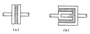
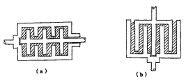
本発明に言う流体を用いた回転トルクの伝達あるいは停止装置とは、対向するディスク(AとB)あるいはシリンダー(AとB)の間に介在させた流体の粘性や剪断力をトルク伝達や停止に利用する装置であり、ディスクあるいはシリンダーがそれぞれ一対(AとB、一重)である基本的な装置の断面構造をモデル的に図1の(a)および(b)に示す。斜線は液体を示す。図2の(a)はディスクを多重にしたものを(b)はシリンダーを多重にしたものをモデル的に示す。媒体の液体(斜線で示す)はディスクAとBあるいはシリンダーAとBの間に充填されている。トルク伝達の場合、AおよびBはいずれかの一方が入力回転軸に、他方が出力回転軸に繋がっており、またトルク停止の場合、AあるいはBのいずれか一方は停止して用いられる。トルクの発生はディスクあるいはシリンダーのAとBの流体の充填された対向面であり、対向面を構成する部分をトルク発生部と呼ぶ。 The device for transmitting or stopping the rotational torque using the fluid according to the present invention means that the viscosity or shear force of the fluid interposed between the opposing disks (A and B) or cylinders (A and B) is transmitted and stopped. 1A and 1B schematically show a cross-sectional structure of a basic device having a pair of disks or cylinders (A and B, single). The diagonal lines indicate liquid. FIG. 2A shows a model in which disks are multiplexed, and FIG. 2B shows a model in which cylinders are multiplexed. The medium liquid (shown by diagonal lines) is filled between discs A and B or cylinders A and B. In the case of torque transmission, one of A and B is connected to the input rotation shaft and the other is connected to the output rotation shaft. In the case of torque stop, either A or B is stopped and used. Torque is generated on the opposing surfaces of the disc or cylinder filled with fluids A and B, and the portion constituting the opposing surface is called a torque generating portion.
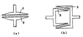
本発明に言う固定部から離れるほど肉薄になるディスクあるいはシリンダーの断面形状を図3にモデル的に示したものであり、(a)はディスク型の場合を、(b)はシリンダー型の場合を示す。斜線部は流体を示す。図3の(a)および(b)のそれぞれのディスクおよびシリンダーの断面は図4の(a)、(b)、(c)などに示すような変形形状をとることができる。(a)は一方の面が面方向に平行で他方が斜めに、(b)は両方の面が斜めに、(c)は一方の面が曲線的勾配面に他方が平行になったものを示す。ディスクやシリンダーの固定部とは反対側の先端部は点線で示すように尖ったものであっても良い。 FIG. 3 schematically shows the cross-sectional shape of a disk or cylinder that becomes thinner as it moves away from the fixed portion according to the present invention. (A) shows the case of a disk type, and (b) shows the case of a cylinder type. Show. The shaded area indicates the fluid. The cross sections of the respective disks and cylinders shown in FIGS. 3A and 3B can take a deformed shape as shown in FIGS. 4A, 4B, and 4C. (A) One surface is parallel to the surface direction and the other is oblique, (b) is both surfaces oblique, (c) is one surface parallel to a curved gradient surface and the other is parallel. Show. The tip portion on the opposite side of the fixed portion of the disk or cylinder may be sharp as shown by the dotted line.
図2(a)の多重ディスク型や(b)の多重シリンダー型の場合も同様に、図4の(a)、(b)、(c)などに示すような断面形状を取ることができる。一枚のディスクやシリンダーの場合、あるいは多重の両端部のディスクやシリンダーの場合、最も外側のディスクやシリンダーのAあるいはBのいずれか一方の断面形状は図4のような形状でなくともよい。なお多重ディスク型の場合、ディスク形状は一般に中央部が抜けたドーナツ型で使用される。 Similarly, in the case of the multiple disk type of FIG. 2A and the multiple cylinder type of FIG. 2B, a cross-sectional shape as shown in FIG. 4A, FIG. 4B, FIG. In the case of a single disk or cylinder, or in the case of a disk or cylinder at multiple ends, the cross-sectional shape of either A or B of the outermost disk or cylinder does not have to be the shape shown in FIG. In the case of a multi-disk type, the disk shape is generally used as a donut shape with the central portion omitted.
固定部とは対向ディスクあるいは対向シリンダーを回転軸あるいは回転筒に取り付け固定する部分である。ディスク型の場合、固定部の上下または左右の2面がディスク面に対して平行なものは重ね合わせて使用するのに都合が良い。ディスクやシリンダーを多重にした多重型の場合、重ねあうディスクあるいはシリンダーの固定部の間には一定間隔を保つためにドーナツ状のスペーサーが挟まれる。ディスクやシリンダーの固定部の厚さをこのスペーサー分の厚さ分だけ予め厚くし一体物としてディスクやシリンダーを製作するのも組み立て精度の点で望ましい。
回転軸や回転筒への固定には一般に位置合わせのピンやボルトの使用や、はめ込みなどの方法が用いられる。The fixed portion is a portion that attaches and fixes the opposing disk or the opposing cylinder to the rotating shaft or the rotating cylinder. In the case of the disc type, it is convenient to use the fixed portion in which the upper and lower or left and right surfaces are parallel to the disc surface. In the case of a multiplex type with multiple disks and cylinders, donut-shaped spacers are sandwiched between the fixed parts of the overlapping disks or cylinders in order to maintain a constant spacing. It is also desirable from the viewpoint of assembly accuracy that the thickness of the fixed portion of the disk or cylinder is increased in advance by the thickness of the spacer and the disk or cylinder is manufactured as an integral body.
For fixing to the rotating shaft or the rotating cylinder, a method such as use of an alignment pin or bolt or fitting is generally used.
対向ディスクあるいは対向シリンダーの断面の厚さが固定部から離れるほど肉薄になる程度に関しては、ディスクやシリンダーの先端部の厚さ(T1)と固定部の厚さ(T2)の比(T1/T2)が大きい(1に近い)と本発明の効果は少なく、この比は1/2以下、できれば1/3以下であることが望ましい。 Regarding the extent to which the cross-sectional thickness of the opposing disk or opposing cylinder becomes thinner the further away from the fixed part, the ratio of the thickness (T1) of the tip of the disk or cylinder (T1) to the thickness (T2) of the fixed part (T1 / T2) ) Is large (close to 1), the effect of the present invention is small, and this ratio is desirably 1/2 or less, preferably 1/3 or less.
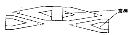
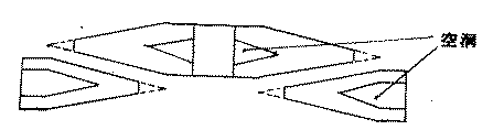
ディスクやシリンダーの内部には、図5の(a)や(b)のような溝を部分的に設けて空洞にして表面積を増やし空気や冷却水で効率よく冷却することも可能である。ディスクやシリンダーの対向面間の間隔は一般に一定値であることが望ましく、またディスクやシリンダーの製作時や取り付け時の寸法精度を上げることは安定したトルク伝達や停止の性能を長期間持続して発現させる上で重要である。 It is also possible to provide a groove as shown in FIGS. 5 (a) and 5 (b) partially inside the disk or cylinder to increase the surface area and efficiently cool with air or cooling water. In general, it is desirable that the distance between the opposing surfaces of the disk and cylinder be a constant value.In addition, increasing the dimensional accuracy during manufacture and installation of the disk and cylinder will maintain stable torque transmission and stopping performance for a long period of time. It is important for expression.
本発明に用いられる流体としては比較的粘度の高い機械油や電場や磁場により粘性が変化するエレクトロレオロジー(ER)流体やマグネトロレオロジー(MR)流体、あるいは所定の剪断速度以上になると急激な粘度を伴うダイラタンシー流体などが使用される。ER流体を使用する場合は、対向ディスクや対向シリンダーの対向面には正負の電極が形成され、ER流体に印加される高電圧にも耐えられように対向ディスクや対向シリンダーの間は完全に絶縁されていることが必要である。 The fluid used in the present invention is a relatively high viscosity machine oil, an electrorheological (ER) fluid or a magnetorheological (MR) fluid whose viscosity changes due to an electric field or a magnetic field, or an abrupt viscosity when a predetermined shear rate is exceeded. A dilatancy fluid with a fluid is used. When using ER fluid, positive and negative electrodes are formed on the opposing surfaces of the opposing disk and cylinder, and the opposing disk and cylinder are completely insulated to withstand the high voltage applied to the ER fluid. It is necessary to be.
MR流体の場合は対向面に磁場がかけられるように電磁石が設置される。ER流体を用いたトルク伝達や停止装置は一般に応答性やトルク慣性比に優れセールスポイントになっているが、本発明のディスクやシリンダーの構造はこれらの性能を一層向上させるものとして好都合である。 In the case of MR fluid, an electromagnet is installed so that a magnetic field can be applied to the opposing surface. Torque transmission and stop devices using ER fluid are generally excellent in responsiveness and torque inertia ratio and are selling points. However, the structure of the disk and cylinder of the present invention is advantageous for further improving these performances.
厚さ均一なディスクやシリンダーを多重に積層した同じ大きさのトルクを伝達あるいは停止する同一直径(外周径)の従来の装置に比較して、本発明の装置は積層部の厚みを実質的に薄くすることが可能でコンパクト化できるとともに、回転慣性を大幅に低減でき、更に熱伝導性(除熱)も向上できる。 Compared with a conventional device of the same diameter (outer diameter) that transmits or stops the same magnitude of torque, in which multiple discs and cylinders of uniform thickness are laminated, the device of the present invention substantially reduces the thickness of the laminated portion. The thickness can be reduced and the size can be reduced, the rotational inertia can be greatly reduced, and the thermal conductivity (heat removal) can be improved.
以下、実施例をもって本発明の内容を補足する。 Hereinafter, the contents of the present invention will be supplemented with examples.
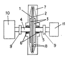
(実施例1)底辺(ディスク直径)が100.0mm、上辺(軸心と固定部)が50.0mm、高さ(固定部の厚さ)が1.00mm、先端部の厚さが0.30mmの2枚のSS400製(表面はニッケルメッキ加工)のディスク1および2を用意した。 (Example 1) The bottom side (disk diameter) is 100.0 mm, the top side (axial center and fixed part) is 50.0 mm, the height (thickness of the fixed part) is 1.00 mm, and the tip part thickness is 0.00. Two 30 mm disks made of SS400 (the surface was nickel-plated) were prepared.
軸端部に固定用円板3を形成した直径10.0mmの2個の回転軸4および5にボルトでこれらのディスクを軸に垂直に固定して、ディスク間隔1.00mmで対向させた構造の図6のトルク伝達装置を製作した。左右のディスクの軸受け部6は、Oリングシール(図示せず)でシールされ、また樹脂製のベアリングガイド(図示せず)で絶縁された軸受けベアリング(図示せず)が取り付けられている。 A structure in which two disks 10.0 and 5 having a diameter of 10.0 mm with a
ディスク間隙には電圧(0−2000V)が印加できるように左右の回転軸にそれぞれ電極ブラシ(図示せず)が取り付けられている。ディスク間隙およびハウジング7の空洞部には分散系ER流体(株式会社ERテック製、ED2520)8が充填されている。左右の回転軸には絶縁カプラー9を介して一方にはモータ10が、他方にはトルク計11が取り付けられている。トルク計11はER流体に印加する電圧を制御するパソコン(図示せず)に接続され印加電圧、回転トルクが時間とともに記録される。 Electrode brushes (not shown) are attached to the left and right rotating shafts so that a voltage (0 to 2000 V) can be applied to the disc gap. The disk gap and the cavity of the
一方、比較例1として、上記形状のディスクの代わりに厚さのみが1.00mm均一で他は同一の従来型ディスクを取り付け、性能の比較試験を行った。
その結果、実施例1と比較例では下記の通り、回転初期の慣性トルク(空回転時)、トルク/慣性比、電圧印加(1000V)時のトルクの立ち上がり応答速度、電圧切断時の立下り応答速度に明確な差がみられた。On the other hand, as Comparative Example 1, instead of the disk having the above-described shape, a conventional disk having a uniform thickness of only 1.00 mm was attached, and a performance comparison test was performed.
As a result, in Example 1 and the comparative example, as shown below, inertia torque at the initial rotation (during idle rotation), torque / inertia ratio, torque rising response speed when voltage is applied (1000 V), falling response when voltage is disconnected There was a clear difference in speed.
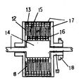
(実施例2)外径120.0mm、内径60.0mm、外周部(幅10.0mm)を固定部(厚さ1.00mm、幅10.0mm)としてディスク中心部に進むほど直線的に薄くなったドーナツ状のSS400製(表面はニッケルメッキ加工)のディスク(内端部の厚さ:0.30mm)12を10枚と、外径120.0mm、内径106.0mm、厚さ2.00mmのステンレス製のスペーサー13を9枚用意した。 (Example 2) The outer diameter is 120.0 mm, the inner diameter is 60.0 mm, the outer peripheral part (width 10.0 mm) is a fixed part (thickness 1.00 mm, width 10.0 mm), and linearly becomes thinner toward the center of the disk. Ten donut-shaped SS400 discs (the surface is nickel-plated) (inner end thickness: 0.30 mm) 12 disks, outer diameter 120.0 mm, inner diameter 106.0 mm, thickness 2.00 mm Nine
また実施例1で用いたディスク1と同一寸法ではあるが中央部に回転軸(軸径:両端部10.0mm、中央部40.0mm)14を貫通させる直径40.0mmの穴を空けたディスク15を9枚、更に外径55.0mm、内径40.0mm、厚さ2.00mmのステンレス製のドーナツ状のスペーサー16を8枚用意した。外径126mm、内径120mmのステンレス製ハウジング17の内部に、これを貫通する直径10.0mmの回転軸14を中心にして、図7に示すようにディスク12スペーサー13、ディスク15、スペーサー16の順に交互に上記全てのディスク類とスペーサー類を積層した。図8はディスクとスペーサーの配列状態を拡大して示す。In addition, a disk having the same dimensions as the
ハウジング17の側面は回転軸14を中心にしてハウジング17自体も回転するように駆動ギア18が取り付けられている。ディスク12はハウジング17に固定されハウジング17と一体となって回転する。一方、ディスク15は回転軸14に固定され回転軸14一体となって回転する。ディスク12とディスク14の間隙はハウジング17の軸受け部19に取り付けられたボルト(図示せず、回転軸14を締め付ける方式)で調整できる構造になっている。 A
回転軸14の軸受け部とハウジング17は実施例1と同様、左右の軸受け部6がOリングシール(図示せず)でシールされ、また樹脂製のベアリングガイド(図示せず)で絶縁された軸受けベアリング(図示せず)が取り付けられている。ディスク12とディスク15の間隙には電圧(0−3000V)がかけられるように回転軸14には電極ブラシ(図示せず、陽極)およびハウジング17にはアース(負極)が取り付けられている。ディスク間隙およびハウジング7の空洞部には実施例1と同様に粒子分散系のER流体(株式会社ERテック製、ED2520)8が充填されている。 As in the first embodiment, the bearing portion of the
比較例2として、実施例2に厚さが1.00mmで均一な点以外は同一寸法のディスク12代替を7枚と15代替を7枚、および厚さが3.00mmである以外は同一寸法のスペーサー13代替を7枚と16代替を6枚、製作して実施例2と同様にこれらを交互に積層して組み立て、同様にER流体を充填した。 As Comparative Example 2, the same dimensions except that the
実施例1と同様に回転軸に絶縁カプラーを介して、一方にはモータを、他方にはトルク計11を取り付け、パソコンからER流体に電圧を印加して、回転トルクの状況を測定した。In the same manner as in Example 1, a motor was attached to one of the rotating shafts via an insulating coupler, a torque meter 11 was attached to the other, and a voltage was applied to the ER fluid from a personal computer to measure the state of rotational torque.
一方、比較例2として、上記形状のディスクの代わりに厚さのみが1.00mm均一で他は同一の従来型ディスクを取り付け、性能の比較試験を行った。
実施例2と比較例2では、回転初期の慣性トルク(空回転時)、トルク/慣性比、電圧印加(1000V)時のトルクの立ち上がり応答速度、電圧切断時の立下り応答速度には下記の通り明確な差がみられた。On the other hand, as Comparative Example 2, instead of the disk having the above shape, a conventional disk having a uniform thickness of only 1.00 mm was attached, and a performance comparison test was performed.
In Example 2 and Comparative Example 2, inertia torque at the initial stage of rotation (during idle rotation), torque / inertia ratio, torque rising response speed when voltage is applied (1000 V), and falling response speed at voltage disconnection are as follows: There was a clear difference.
またER流体に1000Vの電圧を印加したまま、モータを60rpmで30分間回転し続けたところ、実施例2の発生トルクは比較例2と比べて約120%と高いにもかかわらず、ハウジングの表面温度は、比較例では48℃まで上がったが、実施例2では43℃で飽和した。 Further, when the motor was continuously rotated at 60 rpm for 30 minutes while a voltage of 1000 V was applied to the ER fluid, the generated torque of Example 2 was about 120% higher than that of Comparative Example 2, but the surface of the housing. The temperature rose to 48 ° C. in the comparative example, but saturated at 43 ° C. in Example 2.
(実施例3)
実施例2で用いた装置にER流体の代わりに1000ポイズのシリコーンオイルを充填して、1800rpmの回転速度で30分間連続回転させた。比較例3として比較例2と同一の従来型のディスクと上記シリコーンオイルに交換して、実施例3と同様に1800rpmで30分間連続回転させた。その結果、実施例3の発生トルクは比較例3と比べて約130%と高く、表面温度も実施例3は65℃まで、比較例3は60℃まで上昇した。表面温度が比較例3より実施例3が高かったが、同じ発生トルクとなるように比較例3の回転速度を下げた試験ではやはり実施例3の方が3℃程度低かった。(Example 3)
The apparatus used in Example 2 was filled with 1000 poise of silicone oil instead of ER fluid, and continuously rotated at a rotation speed of 1800 rpm for 30 minutes. As Comparative Example 3, the same conventional disk as in Comparative Example 2 and the above silicone oil were replaced, and the mixture was continuously rotated at 1800 rpm for 30 minutes as in Example 3. As a result, the torque generated in Example 3 was as high as about 130% compared to Comparative Example 3, and the surface temperature also increased to 65 ° C in Example 3 and to 60 ° C in Comparative Example 3. Although the surface temperature of Example 3 was higher than that of Comparative Example 3, in the test in which the rotational speed of Comparative Example 3 was lowered so as to have the same generated torque, Example 3 was still lower by about 3 ° C.
なお、初期回転トルクやトルク/慣性比は高粘度のシリコーンオイルを用いた場合、実施例3と比較例3では特徴は見られず、これらの特性に関しては、粘性が外部的に制御できるER流体やMR流体に特徴的であり、本発明の効果はER流体やMR流体に特に優れると言える。 In addition, when the high viscosity silicone oil is used for the initial rotational torque and the torque / inertia ratio, there is no characteristic in Example 3 and Comparative Example 3, and regarding these characteristics, the ER fluid whose viscosity can be controlled externally It is characteristic of MR fluid and MR fluid, and it can be said that the effect of the present invention is particularly excellent for ER fluid and MR fluid.
本発明は、慣性が小さく熱伝達性(除熱性)の良い軽量かつ薄型の流体を用いたトルク伝達あるいは停止装置として、各種の産業機器や車両、電気製品などに幅広く利用される。 INDUSTRIAL APPLICABILITY The present invention is widely used in various industrial equipment, vehicles, electrical products and the like as a torque transmission or stopping device using a light and thin fluid with small inertia and good heat transfer (heat removal).
1 ディスクA
2 ディスクB
3 ディスク固定円板
4 回転軸
5 回転軸
6 軸受け部
7 ハウジング
8 ER流体
9 絶縁性カプラー
10 モータ
11 トルク計
12 ディスク(多重、外周側)
13 スペーサー(外周側)
14 回転軸
15 ディスク(内周側)
16 スペーサー(内周側)
17 ハウジング側面板
18 回転ギア
19 ハウジング軸受け部1 Disc A
2 Disc B
3 Disc Fixed Disc 4 Rotating Shaft 5 Rotating Shaft 6
13 Spacer (outside)
14 Rotating
16 Spacer (Inner circumference side)
17
Claims (3)
Priority Applications (1)
| Application Number | Priority Date | Filing Date | Title |
|---|---|---|---|
| JP2004134836A JP2005291482A (en) | 2004-03-31 | 2004-03-31 | Torque transmitting/stopping device |
Applications Claiming Priority (1)
| Application Number | Priority Date | Filing Date | Title |
|---|---|---|---|
| JP2004134836A JP2005291482A (en) | 2004-03-31 | 2004-03-31 | Torque transmitting/stopping device |
Publications (1)
| Publication Number | Publication Date |
|---|---|
| JP2005291482A true JP2005291482A (en) | 2005-10-20 |
Family
ID=35324624
Family Applications (1)
| Application Number | Title | Priority Date | Filing Date |
|---|---|---|---|
| JP2004134836A Pending JP2005291482A (en) | 2004-03-31 | 2004-03-31 | Torque transmitting/stopping device |
Country Status (1)
| Country | Link |
|---|---|
| JP (1) | JP2005291482A (en) |
Cited By (6)
| Publication number | Priority date | Publication date | Assignee | Title |
|---|---|---|---|---|
| JP2009540379A (en) * | 2006-06-14 | 2009-11-19 | コミッサリア タ レネルジー アトミーク | A performance keyboard comprising a tactile or skin sensation simulation device and at least one similar simulation device |
| JP2010537922A (en) * | 2007-09-07 | 2010-12-09 | オーチス エレベータ カンパニー | Elevator brake using magnetic fluid |
| JP2011007087A (en) * | 2009-06-24 | 2011-01-13 | Denso Corp | Valve timing adjusting device |
| JP2013542384A (en) * | 2010-10-20 | 2013-11-21 | ドレッサー ランド カンパニー | Variable speed magnetic shaft coupling |
| CN105545789A (en) * | 2016-02-25 | 2016-05-04 | 太仓钰丰机械工程有限公司 | Low-resistance silicone oil fan clutch |
| JP2019032050A (en) * | 2017-08-09 | 2019-02-28 | 株式会社栗本鐵工所 | Rotation braking device |
Citations (6)
| Publication number | Priority date | Publication date | Assignee | Title |
|---|---|---|---|---|
| JPH06185545A (en) * | 1992-12-16 | 1994-07-05 | Bridgestone Corp | Shaft coupling and using method thereof |
| JPH07248033A (en) * | 1994-03-11 | 1995-09-26 | Nissan Motor Co Ltd | Electric control motion transmission method and motion transmission device |
| JPH086763B2 (en) * | 1989-05-15 | 1996-01-29 | 東海ゴム工業株式会社 | Torque transmission device using electrorheological fluid |
| JPH0914300A (en) * | 1995-06-30 | 1997-01-14 | Shinko Electric Co Ltd | Torque transmission device using electrorheological fluid |
| JPH1182556A (en) * | 1997-09-17 | 1999-03-26 | Komatsu Ltd | Equipment using electrorheological fluid |
| JPH11132259A (en) * | 1997-08-19 | 1999-05-18 | Bayer Ag | Clutch |
-
2004
- 2004-03-31 JP JP2004134836A patent/JP2005291482A/en active Pending
Patent Citations (6)
| Publication number | Priority date | Publication date | Assignee | Title |
|---|---|---|---|---|
| JPH086763B2 (en) * | 1989-05-15 | 1996-01-29 | 東海ゴム工業株式会社 | Torque transmission device using electrorheological fluid |
| JPH06185545A (en) * | 1992-12-16 | 1994-07-05 | Bridgestone Corp | Shaft coupling and using method thereof |
| JPH07248033A (en) * | 1994-03-11 | 1995-09-26 | Nissan Motor Co Ltd | Electric control motion transmission method and motion transmission device |
| JPH0914300A (en) * | 1995-06-30 | 1997-01-14 | Shinko Electric Co Ltd | Torque transmission device using electrorheological fluid |
| JPH11132259A (en) * | 1997-08-19 | 1999-05-18 | Bayer Ag | Clutch |
| JPH1182556A (en) * | 1997-09-17 | 1999-03-26 | Komatsu Ltd | Equipment using electrorheological fluid |
Cited By (8)
| Publication number | Priority date | Publication date | Assignee | Title |
|---|---|---|---|---|
| JP2009540379A (en) * | 2006-06-14 | 2009-11-19 | コミッサリア タ レネルジー アトミーク | A performance keyboard comprising a tactile or skin sensation simulation device and at least one similar simulation device |
| JP2010537922A (en) * | 2007-09-07 | 2010-12-09 | オーチス エレベータ カンパニー | Elevator brake using magnetic fluid |
| US8631917B2 (en) | 2007-09-07 | 2014-01-21 | Otis Elavator Company | Elevator brake with magneto-rheological fluid |
| JP2011007087A (en) * | 2009-06-24 | 2011-01-13 | Denso Corp | Valve timing adjusting device |
| JP2013542384A (en) * | 2010-10-20 | 2013-11-21 | ドレッサー ランド カンパニー | Variable speed magnetic shaft coupling |
| CN105545789A (en) * | 2016-02-25 | 2016-05-04 | 太仓钰丰机械工程有限公司 | Low-resistance silicone oil fan clutch |
| JP2019032050A (en) * | 2017-08-09 | 2019-02-28 | 株式会社栗本鐵工所 | Rotation braking device |
| JP7161844B2 (en) | 2017-08-09 | 2022-10-27 | 株式会社栗本鐵工所 | rotary braking device |
Similar Documents
| Publication | Publication Date | Title |
|---|---|---|
| US8869653B2 (en) | Drive apparatus for hybrid vehicle | |
| CN102506094A (en) | Multi-disc type fine-pitch magnetorheological clutch | |
| CN101793312A (en) | Magneto-rheological stepless speed changer | |
| CN101535672A (en) | Clutch device | |
| CN101029664A (en) | Magnetic rheological hydraulic flexible starter | |
| CN103538471A (en) | Power divider and power assembly | |
| CN101319695B (en) | Magneto-rheological fluid soft starting device | |
| JP2005291482A (en) | Torque transmitting/stopping device | |
| CN105952810A (en) | Electromagnetic extrusion conical magnetorheological fluid self-pressurization clutch | |
| CN109931339B (en) | Clutch device, multiple clutch device, electric drive unit and drive assembly for a motor vehicle | |
| CN112840139A (en) | Magneto-Rheological Fluid Clutch Device with Low Permeation Drum | |
| CN102359513A (en) | Water-cooled magnetorheological soft start device | |
| CN202073954U (en) | Electrorheological automatic clutch for automobile | |
| CN103453049A (en) | Cooling type large-power magnetorheological clutch in disc | |
| CN106555827A (en) | Automobile and its wet type double clutch gearbox, wet-type dual-clutch | |
| CN101915277B (en) | Uniwafer three-disk magnetic rheological clutch | |
| CN102312939B (en) | Clutch of magneto rheological fluid (MRF) fan | |
| CN104565120B (en) | A kind of magnetic flow liquid becomes torquer | |
| CN114033808A (en) | An integral spiral labyrinth damping coupling | |
| CN204371988U (en) | Magnetic flow liquid becomes torquer | |
| CN203308964U (en) | Roller type electromagnetic clutch | |
| CN102278446A (en) | Soft startup device using magnetorheological fluid | |
| CN212509274U (en) | A magnetorheological soft starter based on centrifugal extrusion of a hemisphere | |
| CN214465713U (en) | Double-cylinder type magnetorheological brake made of shape memory alloy | |
| CN110435882B (en) | Aircraft brake device based on piezoelectric drive flexible displacement amplification mechanism |
Legal Events
| Date | Code | Title | Description |
|---|---|---|---|
| A621 | Written request for application examination |
Free format text: JAPANESE INTERMEDIATE CODE: A621 Effective date: 20070301 |
|
| A977 | Report on retrieval |
Effective date: 20100531 Free format text: JAPANESE INTERMEDIATE CODE: A971007 |
|
| A131 | Notification of reasons for refusal |
Free format text: JAPANESE INTERMEDIATE CODE: A131 Effective date: 20100608 |
|
| A02 | Decision of refusal |
Effective date: 20101109 Free format text: JAPANESE INTERMEDIATE CODE: A02 |