JP2005291590A - Ultra-high temperature flame generating method, ultra-high temperature combustion furnace, garbage incinerator, and flue gas cooling device - Google Patents
Ultra-high temperature flame generating method, ultra-high temperature combustion furnace, garbage incinerator, and flue gas cooling device Download PDFInfo
- Publication number
- JP2005291590A JP2005291590A JP2004105294A JP2004105294A JP2005291590A JP 2005291590 A JP2005291590 A JP 2005291590A JP 2004105294 A JP2004105294 A JP 2004105294A JP 2004105294 A JP2004105294 A JP 2004105294A JP 2005291590 A JP2005291590 A JP 2005291590A
- Authority
- JP
- Japan
- Prior art keywords
- high temperature
- garbage
- ultra
- oxygen
- temperature flame
- Prior art date
- Legal status (The legal status is an assumption and is not a legal conclusion. Google has not performed a legal analysis and makes no representation as to the accuracy of the status listed.)
- Pending
Links
- 238000002485 combustion reaction Methods 0.000 title claims abstract description 31
- 238000000034 method Methods 0.000 title claims abstract description 8
- 239000010813 municipal solid waste Substances 0.000 title claims description 41
- 238000001816 cooling Methods 0.000 title claims description 15
- UGFAIRIUMAVXCW-UHFFFAOYSA-N Carbon monoxide Chemical compound [O+]#[C-] UGFAIRIUMAVXCW-UHFFFAOYSA-N 0.000 title 1
- 239000003546 flue gas Substances 0.000 title 1
- QVGXLLKOCUKJST-UHFFFAOYSA-N atomic oxygen Chemical compound [O] QVGXLLKOCUKJST-UHFFFAOYSA-N 0.000 claims abstract description 35
- 239000001301 oxygen Substances 0.000 claims abstract description 35
- 229910052760 oxygen Inorganic materials 0.000 claims abstract description 35
- 239000000571 coke Substances 0.000 claims abstract description 26
- UFHFLCQGNIYNRP-UHFFFAOYSA-N Hydrogen Chemical compound [H][H] UFHFLCQGNIYNRP-UHFFFAOYSA-N 0.000 claims abstract description 15
- 239000001257 hydrogen Substances 0.000 claims abstract description 14
- 229910052739 hydrogen Inorganic materials 0.000 claims abstract description 14
- 241000287828 Gallus gallus Species 0.000 claims description 23
- XLYOFNOQVPJJNP-UHFFFAOYSA-N water Substances O XLYOFNOQVPJJNP-UHFFFAOYSA-N 0.000 claims description 21
- 239000007789 gas Substances 0.000 claims description 19
- HEMHJVSKTPXQMS-UHFFFAOYSA-M Sodium hydroxide Chemical group [OH-].[Na+] HEMHJVSKTPXQMS-UHFFFAOYSA-M 0.000 claims description 12
- 239000003054 catalyst Substances 0.000 claims description 10
- 239000000498 cooling water Substances 0.000 claims description 5
- 239000000446 fuel Substances 0.000 claims description 5
- 239000002440 industrial waste Substances 0.000 claims description 5
- 238000011084 recovery Methods 0.000 claims description 4
- 238000000926 separation method Methods 0.000 claims description 3
- 239000003595 mist Substances 0.000 claims description 2
- 239000000779 smoke Substances 0.000 claims description 2
- 238000007599 discharging Methods 0.000 abstract 1
- 238000004079 fireproofing Methods 0.000 abstract 1
- OKTJSMMVPCPJKN-UHFFFAOYSA-N Carbon Chemical compound [C] OKTJSMMVPCPJKN-UHFFFAOYSA-N 0.000 description 6
- VYPSYNLAJGMNEJ-UHFFFAOYSA-N Silicium dioxide Chemical compound O=[Si]=O VYPSYNLAJGMNEJ-UHFFFAOYSA-N 0.000 description 6
- 238000010586 diagram Methods 0.000 description 5
- 230000005611 electricity Effects 0.000 description 5
- 229910052751 metal Inorganic materials 0.000 description 5
- 239000002184 metal Substances 0.000 description 5
- 239000002699 waste material Substances 0.000 description 5
- LFQSCWFLJHTTHZ-UHFFFAOYSA-N Ethanol Chemical compound CCO LFQSCWFLJHTTHZ-UHFFFAOYSA-N 0.000 description 4
- 238000000354 decomposition reaction Methods 0.000 description 4
- 150000002013 dioxins Chemical group 0.000 description 4
- 238000001035 drying Methods 0.000 description 4
- VNWKTOKETHGBQD-UHFFFAOYSA-N methane Chemical compound C VNWKTOKETHGBQD-UHFFFAOYSA-N 0.000 description 4
- 239000011449 brick Substances 0.000 description 3
- 238000010438 heat treatment Methods 0.000 description 3
- 239000007788 liquid Substances 0.000 description 3
- 239000000463 material Substances 0.000 description 3
- 239000000741 silica gel Substances 0.000 description 3
- 229910002027 silica gel Inorganic materials 0.000 description 3
- WQZGKKKJIJFFOK-GASJEMHNSA-N Glucose Natural products OC[C@H]1OC(O)[C@H](O)[C@@H](O)[C@@H]1O WQZGKKKJIJFFOK-GASJEMHNSA-N 0.000 description 2
- KDLHZDBZIXYQEI-UHFFFAOYSA-N Palladium Chemical compound [Pd] KDLHZDBZIXYQEI-UHFFFAOYSA-N 0.000 description 2
- 239000003610 charcoal Substances 0.000 description 2
- 230000000694 effects Effects 0.000 description 2
- 239000008103 glucose Substances 0.000 description 2
- BASFCYQUMIYNBI-UHFFFAOYSA-N platinum Chemical compound [Pt] BASFCYQUMIYNBI-UHFFFAOYSA-N 0.000 description 2
- 238000010248 power generation Methods 0.000 description 2
- 239000007787 solid Substances 0.000 description 2
- 102000004190 Enzymes Human genes 0.000 description 1
- 108090000790 Enzymes Proteins 0.000 description 1
- 240000004808 Saccharomyces cerevisiae Species 0.000 description 1
- BQCADISMDOOEFD-UHFFFAOYSA-N Silver Chemical compound [Ag] BQCADISMDOOEFD-UHFFFAOYSA-N 0.000 description 1
- 150000001298 alcohols Chemical class 0.000 description 1
- PNEYBMLMFCGWSK-UHFFFAOYSA-N aluminium oxide Inorganic materials [O-2].[O-2].[O-2].[Al+3].[Al+3] PNEYBMLMFCGWSK-UHFFFAOYSA-N 0.000 description 1
- 238000007664 blowing Methods 0.000 description 1
- 239000004566 building material Substances 0.000 description 1
- 239000001913 cellulose Substances 0.000 description 1
- 229920002678 cellulose Polymers 0.000 description 1
- 230000000739 chaotic effect Effects 0.000 description 1
- 238000006243 chemical reaction Methods 0.000 description 1
- 239000013078 crystal Substances 0.000 description 1
- 230000006378 damage Effects 0.000 description 1
- 239000010791 domestic waste Substances 0.000 description 1
- 238000010891 electric arc Methods 0.000 description 1
- 238000005516 engineering process Methods 0.000 description 1
- 230000007613 environmental effect Effects 0.000 description 1
- 238000001914 filtration Methods 0.000 description 1
- 239000003502 gasoline Substances 0.000 description 1
- 239000005433 ionosphere Substances 0.000 description 1
- 238000004519 manufacturing process Methods 0.000 description 1
- 238000002844 melting Methods 0.000 description 1
- 230000008018 melting Effects 0.000 description 1
- 150000002739 metals Chemical class 0.000 description 1
- 125000002496 methyl group Chemical group [H]C([H])([H])* 0.000 description 1
- 244000005700 microbiome Species 0.000 description 1
- 229910052763 palladium Inorganic materials 0.000 description 1
- 230000002093 peripheral effect Effects 0.000 description 1
- 229910052697 platinum Inorganic materials 0.000 description 1
- 239000004576 sand Substances 0.000 description 1
- 239000000377 silicon dioxide Substances 0.000 description 1
- 229910052709 silver Inorganic materials 0.000 description 1
- 239000004332 silver Substances 0.000 description 1
- 238000001179 sorption measurement Methods 0.000 description 1
- 239000000126 substance Substances 0.000 description 1
- 229940070527 tourmaline Drugs 0.000 description 1
- 229910052613 tourmaline Inorganic materials 0.000 description 1
- 239000011032 tourmaline Substances 0.000 description 1
- 238000009423 ventilation Methods 0.000 description 1
- 239000002918 waste heat Substances 0.000 description 1
Images


Classifications
-
- Y—GENERAL TAGGING OF NEW TECHNOLOGICAL DEVELOPMENTS; GENERAL TAGGING OF CROSS-SECTIONAL TECHNOLOGIES SPANNING OVER SEVERAL SECTIONS OF THE IPC; TECHNICAL SUBJECTS COVERED BY FORMER USPC CROSS-REFERENCE ART COLLECTIONS [XRACs] AND DIGESTS
- Y02—TECHNOLOGIES OR APPLICATIONS FOR MITIGATION OR ADAPTATION AGAINST CLIMATE CHANGE
- Y02E—REDUCTION OF GREENHOUSE GAS [GHG] EMISSIONS, RELATED TO ENERGY GENERATION, TRANSMISSION OR DISTRIBUTION
- Y02E20/00—Combustion technologies with mitigation potential
- Y02E20/12—Heat utilisation in combustion or incineration of waste
Landscapes
- Treating Waste Gases (AREA)
- Vertical, Hearth, Or Arc Furnaces (AREA)
- Waste-Gas Treatment And Other Accessory Devices For Furnaces (AREA)
- Discharge Heating (AREA)
Abstract
Description
この発明は、プラズマ放電、コークス燃焼及び水の分解による水素の燃焼により超高温炎を生成する燃焼炉と、これを利用する生ごみ等焼却装置を得ることを目的とした超高温炎生成方法及び超高温燃焼炉並びに生ごみ等焼却装置とその排気冷却装置に関する。 The present invention relates to a combustion furnace that generates an ultra-high temperature flame by burning hydrogen through plasma discharge, coke combustion, and water decomposition, and an ultra-high temperature flame generating method for the purpose of obtaining an incinerator such as garbage using the same, and The present invention relates to an ultra-high temperature combustion furnace, a garbage incinerator, and an exhaust cooling device thereof.
従来プラズマ放電、アーク放電、各種気体又は液体を燃料とする高温炉が知られており、金属溶融炉又は産業廃棄物の高温焼却炉等に使用されている。 Conventionally, plasma discharge, arc discharge, high temperature furnaces using various gases or liquids as fuels are known, and are used in metal melting furnaces or high temperature incinerators for industrial waste.
前記技術の利用としては、金属電解炉、溶鉱炉、産業廃棄物の焼却炉などとして使用されている。
特に生ごみ(生活廃棄物)又は産業廃棄物(以下、焼却処理物という)が膨大となって、投棄場所の関係上その投棄が困難になり、夫々焼却に望をつないだが、焼却温度が低下(例えば800℃以下)すると、ダイオキシンその他の有害物質の分解が不十分の為に環境破壊のおそれがあり、かつ焼却に際しCO2の排出量が増大するなどの幾多の問題点があった。 In particular, garbage (domestic waste) or industrial waste (hereinafter referred to as incineration waste) becomes enormous, making it difficult to dump due to the location of the dumping place. (For example, 800 ° C. or lower), there are many problems such as environmental destruction due to insufficient decomposition of dioxins and other harmful substances, and increased CO 2 emission during incineration.
そこで大型焼却炉を導入すると共に、連続焼却によって800℃以下の低温焼却を皆無にしようとする対策がとられていたが、CO2の排出量を減少させることはできないという問題点があった。 Thus, while a large incinerator was introduced and measures were taken to eliminate low temperature incineration of 800 ° C. or lower by continuous incineration, there was a problem that the amount of CO 2 emission could not be reduced.
またアーク炉又はプラズマ炉は、熱源が電気放電であるから、必要なエネルギーは総て電気の消費量となる問題点があった。次に、生ごみ焼却炉などにおける廃熱利用については、いまだ不十分であって、熱効率の向上に直結していないという問題点があった。 Further, since the heat source of the arc furnace or the plasma furnace is electric discharge, there is a problem that all necessary energy is consumed by electricity. Next, the use of waste heat in garbage incinerators and the like is still inadequate and has not been directly linked to the improvement of thermal efficiency.
然るにこの発明は、酸素供給下(空気も同じ)において、コークスをプラズマ放電によって高温燃焼(例えば2000℃以上)させ、この高温により生ごみ等を急速高温焼却することにより、燃焼部分に供給した水分及び生ごみ等から分離し、浄化した水分を瞬時に水素と酸素に分解し、その混合ガスを生ごみ等の燃焼に用いて超高温(3000℃以上)を生成し、これにより生ごみ等を焼却処理することに成功したのである。 However, according to the present invention, the moisture supplied to the combustion part is obtained by burning the coke at a high temperature (for example, 2000 ° C. or more) by plasma discharge under oxygen supply (the same applies to air) and rapidly incinerating the garbage at this high temperature. In addition, the water separated from the garbage, etc., is instantly decomposed into hydrogen and oxygen, and the mixed gas is used for combustion of the garbage, etc. to produce ultra-high temperature (3000 ° C or higher). The incineration was successful.
即ち方法の発明は、コークスに酸素(空気)と水分とを供給しつつプラズマ放電させて高温炎を生成し、この高温炎により、前記水分を水素と酸素に分解して、これを燃焼させ、超高温炎を生成することを特徴とした超高温炎生成方法であり、酸素は、加圧酸素又は加熱・加圧空気とするものであり、水分は、雰霧状又は水蒸気として供給するものである。 That is, the invention of the method is to generate a high temperature flame by plasma discharge while supplying oxygen (air) and moisture to the coke, the high temperature flame decomposes the moisture into hydrogen and oxygen, and burns it. An ultra-high temperature flame generating method characterized by generating an ultra-high temperature flame, wherein oxygen is pressurized oxygen or heated / pressurized air, and moisture is supplied as mist or steam. is there.
炉内中心部には、水分を分解した水素が供給されるが、その周囲にはロストル下部より送風ブロワーで空気を供給し、コークスを燃焼させている。送風は風量調整を可能にする機能を備え、炉内の温度調整にも関係する。 Hydrogen which decomposed | disassembled the water | moisture content is supplied to the center part in a furnace, The air is supplied with the ventilation blower from the lower part of a rooster, and coke is burned. Blowing has a function that enables air volume adjustment and is also related to temperature adjustment in the furnace.
また燃焼炉の発明は、耐火壁で囲まれた炉内の中央部にロストルを設置し、該ロストル上へのコークス供給部を設けると共に、放電用の電極を配置し、ロストルの中央部に酸素と水分の供給口を設け、ロストル蓋の上部への焼却処理物の供給部を設けたことを特徴とする超高温燃焼炉である。 In the invention of the combustion furnace, a rooster is installed in the center of the furnace surrounded by a fire wall, a coke supply unit is provided on the rooster, an electrode for discharge is arranged, and an oxygen is installed in the center of the rooster. And a moisture supply port, and an incineration processed product supply unit to the upper part of the rooster cover is provided.
次に焼却装置の発明は、前記記載の超高温燃焼炉へ、燃料供給装置及び焼却処理物供給装置を設けると共に、排気処理装置及び排熱回収装置を付設したことを特徴とする生ごみ等焼却装置であり、焼却処理物は、生ごみ又は産業廃棄物としたものであり、燃料供給装置は、コークス供給装置と、酸素(空気)及び水分供給装置としたものである。また、排気処理装置は、触媒装置、冷却装置及び熱交換器並びに分離装置としたものであり、排熱回収装置は、熱交換器、蒸気タービン及び発電機としたものである。 Next, the incinerator is provided with a fuel supply device and an incineration material supply device, and an exhaust treatment device and an exhaust heat recovery device are attached to the ultrahigh temperature combustion furnace described above. It is an apparatus, the incineration processed material is garbage or industrial waste, and the fuel supply device is a coke supply device, and an oxygen (air) and moisture supply device. Further, the exhaust treatment device is a catalyst device, a cooling device, a heat exchanger, and a separation device, and the exhaust heat recovery device is a heat exchanger, a steam turbine, and a generator.
また、両端部を塞いだ円筒の内側壁に多数の電極を並列設置して、前記円筒を横架すると共に、一側に排煙などの処理気体の供給パイプを連結し、他側に排気パイプと排水パイプを設け、下部へ冷却水の供給パイプを連設したことを特徴とする生ごみ等焼却装置の排気冷却装置であり、冷却水は、水酸化ナトリウム液又は水としたものである。 In addition, a large number of electrodes are installed in parallel on the inner wall of the cylinder closed at both ends, the cylinder is horizontally mounted, a supply pipe for processing gas such as smoke is connected to one side, and an exhaust pipe is connected to the other side. And a drainage pipe, and a cooling water supply pipe is connected to the lower part of the exhaust cooling apparatus for an incinerator for garbage, etc. The cooling water is a sodium hydroxide solution or water.
前記において、プラズマ放電と、コークスの燃焼は超高温炎(2000℃以上)の生成により、水分を瞬時に水素と酸素に分解し、これを燃焼させることを目的としており、生ごみ等の焼却に要する熱量の60%〜70%は、水分の分解により生成された水素と酸素を使用する。従って、生ごみ等の焼却処理に拘らず、発生するCO2を著しく少なくして多量の廃棄物を処理することができる。 In the above, plasma discharge and coke combustion are intended to instantly decompose water into hydrogen and oxygen by the generation of an ultra-high temperature flame (2000 ° C. or higher) and burn it. 60% to 70% of the amount of heat required uses hydrogen and oxygen produced by the decomposition of moisture. Therefore, a large amount of waste can be treated with significantly less CO 2 generated, regardless of the incineration treatment of garbage or the like.
前記焼却により生じた高熱排気は、熱交換器によって過熱蒸気として取り出し、タービンを回転させて発電させると共に、タービンからの排気は更に熱交換して乾燥用に使用し、更に焼却炉への空気又は酸素を加熱するのに使用することになる。例えば常温の酸素又は空気を300℃以上の酸素又は空気に加熱するので、熱効率を著しく向上させることができる。 The high-temperature exhaust generated by the incineration is taken out as superheated steam by a heat exchanger, and the turbine is rotated to generate electric power, and the exhaust from the turbine is further used for drying by exchanging heat, and further, air to the incinerator or It will be used to heat oxygen. For example, since oxygen or air at normal temperature is heated to oxygen or air at 300 ° C. or higher, the thermal efficiency can be remarkably improved.
前記タービンにより生じた電気は、焼却装置の放電電源、各種動力への電源及び制御機器の電源として使用する。また余分の電力は工場外の給電又は売電することもできる。 The electricity generated by the turbine is used as a discharge power source for the incinerator, a power source for various powers, and a power source for the control equipment. The extra power can also be supplied or sold outside the factory.
前記燃焼炉中には、コークスの燃焼にプラズマ放電が加えられるので、電極間に磁場ができて、磁力線を形成し、化学反応に伴い原子核の回りの電子を遊離して電離層を形成するものと考えられる。従って、原子核と電子とは夫々エネルギーを得て空間を飛び回り、混沌状態となり、液体でも気体でもない状態のプラズマとなる。 In the combustion furnace, since plasma discharge is applied to the combustion of coke, a magnetic field is created between the electrodes, magnetic lines of force are formed, and electrons around the nucleus are liberated along with a chemical reaction to form an ionosphere. Conceivable. Therefore, the nuclei and electrons each gain energy and fly around the space, become a chaotic state, and become plasma that is neither liquid nor gas.
この発明によれば、プラズマ放電によって酸素(空気)供給下でコークスの燃焼速度を速めさせるので(例えば速度が10倍位になる)、超高温炎を生じ、これにより供給した水分、生ごみ等から分離した水分を浄化した後、分解して水素と酸素としてこれを燃焼させるので、超高温燃焼となって、生ごみ等を完全燃焼させることができる効果がある。 According to the present invention, since the combustion speed of coke is increased under the supply of oxygen (air) by plasma discharge (for example, the speed is about 10 times), an ultra-high temperature flame is generated, thereby supplying moisture, garbage, etc. After the water separated from the water is purified, it is decomposed and burned as hydrogen and oxygen, so that it becomes an ultra-high temperature combustion, which has the effect of completely burning garbage and the like.
前記排気は、熱交換して、このエネルギーを電気に変え、前記放電の電源その他に使用し得ると共に、酸素(空気)を加温し、乾燥又は加熱の熱源として使用し、余剰電気は売ることができるなど、エネルギーの自給と、収入源の一部とすることができるなどの効果がある。また発生(使用)エネルギーの量に比し、CO2の発生量が少ないなどの効果があり、排気処理によりCO2の排出を0にすることもできる。 The exhaust can exchange heat, convert this energy into electricity, and can be used as a power source for the discharge, etc., oxygen (air) is heated, used as a heat source for drying or heating, surplus electricity is sold It can be used as a self-sufficiency of energy and a part of the income source. Further, there is an effect that the amount of generated CO 2 is smaller than the amount of generated (used) energy, and CO 2 emission can be reduced to 0 by the exhaust treatment.
前記で生じた灰は、超高温によってガラス質の結晶体となり、他の目的(例えば建材など)に使用することができる。前記燃焼炉を、不完全燃焼の灰の処理に使用すれば、全部硝子質の灰として処理することができる。 The ash produced above becomes a vitreous crystal due to the ultra-high temperature, and can be used for other purposes (for example, building materials). If the combustion furnace is used for the treatment of incompletely burned ash, it can be entirely treated as glassy ash.
また、燃焼は十分な空気が供給される為に、急速燃焼と超高温である為にダイオキシンの生成は不可能なほどの燃焼スピードであり、従ってダイオキシンの生成は不可能である。 In addition, since combustion is supplied with sufficient air, the combustion speed is such that dioxins cannot be generated due to rapid combustion and extremely high temperature, and therefore dioxins cannot be generated.
この発明は、コークスに酸素(空気)と水分を供給すると共に、プラズマ放電させ、これにより容易に超高温炎を生成できる。また、炉内温の立ち上がりを急速にすることが可能である(2000℃以上になる)。 According to the present invention, oxygen (air) and moisture are supplied to coke and plasma discharge is performed, whereby an ultra-high temperature flame can be easily generated. In addition, the rise of the furnace temperature can be made rapid (becomes 2000 ° C. or higher).
そこで前記超高温炎(例えば2000℃以上)を生ごみ等より得た水分にぶつけてこれを分解することにより、水素と酸素を生じるので、これを燃焼させることにより超高温(例えば3000℃以上)で生ごみ等を焼却することができる。 Therefore, hydrogen and oxygen are produced by hitting the ultra high temperature flame (for example, 2000 ° C. or higher) against moisture obtained from garbage, etc., thereby generating hydrogen and oxygen. By burning this, ultra high temperature (for example, 3000 ° C. or higher) You can incinerate garbage.
従って、完全燃焼で廃棄物(砂など)が少なくなると共に、CO2の発生量を激減させ、かつダイオキシンその他の有害ガスは総て分解することができる。 Therefore, complete combustion reduces waste (such as sand), drastically reduces the amount of CO 2 generated, and dioxins and other harmful gases can all be decomposed.
また排気を熱交換し、発電その他に再生利用することができると共に、再生により余分の電気エネルギーを生じた際は、蓄積し、販売し、自給自足することができるので、一旦運転後は、コークスと、生ごみ等を供給するほかは、何等の供給物も不必要になり、余分の電気エネルギーに関しては充電も可能であって、半自立型の生ごみ等焼却装置とすることができる。 Exhaust heat can be exchanged and reused for power generation and other purposes, and when it generates extra electrical energy, it can be stored, sold, and self-sufficient. In addition to supplying garbage and the like, no supply is required, and extra electrical energy can be charged, so that a semi-independent garbage incinerator can be obtained.
この発明を図1の実施例について説明すると、ロストル上へ例えばコークス10kgを供給し、これに200V×50Aでプラズマ放電を発生させると共に、300℃の酸素(又は空気)1時間当り10kg給送すると、高温炎の中心温度2500℃となる。また、生ごみから分離した水分を加温し(300℃以上)、前記コークスの下部から1時間当り300リットルを給送する。前記において、水分は2500℃以上の高温にあって瞬時に水素と酸素に分解し、これを燃焼させることにより3000℃以上の超高温炎を生成することができるので、生ごみは急速に完全燃焼し、無機質(灰)となる。 The present invention will be described with reference to the embodiment of FIG. 1. When, for example, 10 kg of coke is supplied onto a rooster, plasma discharge is generated at 200 V × 50 A, and oxygen (or air) at 300 ° C. is supplied at 10 kg per hour. The center temperature of the high temperature flame is 2500 ° C. Moreover, the water | moisture content isolate | separated from garbage is heated (300 degreeC or more), and 300 liters per hour are fed from the lower part of the said coke. In the above, moisture is decomposed into hydrogen and oxygen instantly at a high temperature of 2500 ° C or higher, and an ultrahigh temperature flame of 3000 ° C or higher can be generated by burning it. And it becomes inorganic (ash).
前記生ごみの燃焼により生じた排気ガスは、第1の触媒層(パラジューム、又は白金など)によりNOX、SOXを分解処理した後、第2の触媒層(例えばシリカ、アルミナなど)によりCO2を吸着処理し、ついで第1の熱交換器で1500℃程度の排気を1000℃以下とし、更に第3の触媒筒により、金属固形物の分離と、前記で処理できなかったCO2を処理し、排気は濾過して微粒固形物を除去した後外界へ排出する。よってCO2は殆んど0になる。 The exhaust gas generated by the combustion of garbage is decomposed into NOX and SOX by a first catalyst layer (palladium or platinum), and then CO 2 is removed by a second catalyst layer (for example, silica, alumina, etc.). Adsorption treatment, and then the exhaust at about 1500 ° C. is set to 1000 ° C. or less in the first heat exchanger, and further, the third catalyst cylinder treats the separation of metal solids and CO 2 that could not be treated as described above, The exhaust is filtered to remove fine solids and then discharged to the outside. Therefore, CO 2 becomes almost zero.
前記触媒筒により冷却排出した水は、タンクへ戻し、再使用に備える。前記熱交換した高温排気(1000℃〜1500℃)は、タービンに供給し、その羽根を回転させて発電機を回転させ、電気を発生させる。 The water cooled and discharged by the catalyst cylinder is returned to the tank to prepare for reuse. The heat-exchanged high-temperature exhaust (1000 ° C. to 1500 ° C.) is supplied to a turbine, and its blades are rotated to rotate a generator and generate electricity.
タービンの排気は、更に熱交換して生ごみなど、供給する可燃物を加熱すると共に、生ごみから出た水を加熱し、蒸気としてコークスの下部へ給送する。また第2の熱交換器を経た排気は、煉瓦などの乾燥空気として使用し、液化した後、再び第1の熱交換器へ戻し、高熱排気と熱交換させ、循環利用する。 The exhaust of the turbine further exchanges heat to heat combustibles to be supplied such as garbage, and heats the water discharged from the garbage and feeds it as steam to the lower part of the coke. Further, the exhaust gas that has passed through the second heat exchanger is used as dry air such as bricks, liquefied, and then returned to the first heat exchanger to exchange heat with high-heat exhaust gas for circulation.
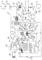
この発明の生ごみ等焼却装置の実施例について説明すると、炉6の中央部へロストル1を設置し、ロストル1上へコークス3を入れて、ロストル1へ放電用電極4、4を設置する。前記ロストル蓋2上へ、生ごみ7を投入し、その上部へNOX、SOXの触媒層8と、CO2の触媒層9を設けて、燃焼炉10を構成する(図2、3)。
An embodiment of an incinerator for garbage such as this invention will be described. A
前記燃焼炉10の排気路11に第1の熱交換器12、冷却装置13を連設し、冷却装置13の排気は、活性炭層14、シリカゲル層15を経て、外界へ放出される。
A
前記第1の熱交換器12を経た高温空気(1000℃〜1500℃)は、タービン16の羽根を回転し、発電機17を回転させて発電し、その排気は、第2の熱交換器18を経て、300℃〜400℃の加熱空気となり、煉瓦工場19の乾燥室へ送られ、水にし、前記第1の熱交換器12へ返される。
The high-temperature air (1000 ° C. to 1500 ° C.) that has passed through the
また第2の熱交換器18で得た加熱空気は、生ごみのホッパー20の下部と、前記燃焼炉10を結ぶロータリーキルン21内の生ごみの加熱に使用し、かつ生ごみから生じた水分を300℃程度に加熱し、蒸気としてロストル1へパイプ22で給送する。
The heated air obtained by the
従ってパイプ22からは、加熱加圧蒸気となって、加熱加圧空気と共に、コークス3内へ供給される。またブロワー55から加圧空気を送り、酸素を供給する。パイプ22aの先端は、パイプ22と共用にしてもよい。酸素が十分送られていれば空気は送らないこともある。
Therefore, from the
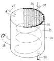
前記冷却装置13は、図5に示すように円筒23の内周壁に電極24、24を並列設置し、一端に排気給送パイプ25を設けると共に、下部に水酸化ナトリウム液の加圧流入パイプ5を接線状に設けて冷却水とし、他側に排気パイプ26と排水パイプ27を設置する。前記排気パイプ26からの排気は、銀塗抹・活性炭層14で有害ガスを分解し、ついでシリカゲル層15で有害ガスを吸着した濾過部を経て外界へ放出される(図2、5)。
As shown in FIG. 5, the
一方排水パイプ27は、気水分離器30、第1水タンク31とポンプP1を経て第2水タンク32を順次連結し、第2水タンク32の給水パイプ33は、ポンプP2とトルマリン入りの処理層34を経て冷却装置13に給水する(図2)。
Meanwhile drain
前記分離器30は、有頂有底の円筒35の内側壁に電極36、36を等間隔に埋設し、上部に冷却装置の排水パイプ27を連結すると共に、排気パイプ37を連結し、下部に第1タンク32と結ぶ排水パイプ38を連結し、側壁下部へ接線状に給気パイプ28が連結してある。前記電極は異金属として、相互間にも微弱電流が通電するようにしてある。
The
図中39は、生ごみ7を投入する炉側のホッパー41上へ上昇する排気収集用のホッパーであって、その排気パイプ42は前記冷却装置の排気パイプ26と連結してある。また29は生ごみ積載車、43は灰積載車、44はホッパー、45はベルトコンベアであって、可燃物を含む灰の場合には、この燃焼炉10を利用して再加熱し、ガラス化することができる。図10中56はシュートである(図2中ホッパー44、ベルトコンベア45は灰の焼却の際にのみ使用する)。
In the figure, 39 is an exhaust collection hopper that rises onto a furnace-
次に46、46aは炭ホッパー及びコークスホッパー、47、47aはベルトコンベア、48は灰取出口である。図中51は水酸化ナトリウム槽、52は定量フィーダー、53は水槽である。前記炭は、触媒層8に詰め込み、CO2の処理を行う為である。
Next, 46 and 46a are charcoal hoppers and coke hoppers, 47 and 47a are belt conveyors, and 48 is an ash removal outlet. In the figure, 51 is a sodium hydroxide tank, 52 is a quantitative feeder, and 53 is a water tank. This is because the charcoal is packed in the
また生ゴミをジスポーザー49にかけ、水と共にバイオタンク50に入れて発酵させ、これにより生じたアルコール分をアルコール槽54に入れ、これを燃焼炉中へ供給することもできる。前記実施例において、コークスをプラズマ放電により高温炎化すると共に、水分の分解により生じた水素と酸素によって超高温化し、これにより生ごみを超高温焼却することができる。
It is also possible to put raw garbage on the disposer 49, put it in the
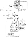
図11により、廃棄物からメタン又は水素を生産するものについて説明すると、廃棄物をジスポーザーに入れて破砕し、このセルローズを酵素により分解してグルコースとし、グルコースに酵母を作用させてアルコールを生産する。このアルコールからメチルを経てガソリンを生産し、又は微生物を利用してメタンガス又は水素ガスを発生させて、これを焼却炉に吹き込み、燃焼させることもできる。 The production of methane or hydrogen from waste will be described with reference to FIG. 11. The waste is put in a disposer and crushed, and the cellulose is decomposed by enzyme into glucose, and yeast is allowed to act on glucose to produce alcohol. . Gasoline can be produced from this alcohol via methyl, or methane gas or hydrogen gas can be generated using microorganisms, which can be blown into an incinerator and burned.
このような超高温焼却により、完全燃焼すると共に、有害ガスを分解して無害状態で放出する。また超高温排気は、熱交換により膨大なエネルギー源となるので、発電及び加熱気体による加熱、乾燥その他に有効利用することができる。 Such ultra-high temperature incineration causes complete combustion, and decomposes harmful gases and releases them harmlessly. Further, since the ultra-high temperature exhaust gas becomes an enormous energy source by heat exchange, it can be effectively used for power generation, heating with a heated gas, drying, and the like.
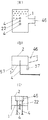
次にこの発明の電極における入力関係を図7に基づいて説明すると、一次側入力60(AC200V単相)を電流調整器61(4〜20mmA又は0〜5V)に接続し、ついでリアクトルトランス62と、炉内の電極4、4に接続する。前記電流調整器61は、自動切換えになっている。
Next, the input relationship in the electrode of the present invention will be described with reference to FIG. 7. The primary side input 60 (AC 200 V single phase) is connected to the current regulator 61 (4 to 20 mmA or 0 to 5 V), and then the
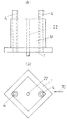
またこの発明のロストル部分を模式図(図8)に基づいて説明すると、ロストル1の中央部に酸素パイプ(加熱空気パイプ)22と電極4、4が設けてある。
The rooster portion of the present invention will be described with reference to a schematic diagram (FIG. 8). An oxygen pipe (heated air pipe) 22 and
前記ロストル1の下部には脚杆57が設けてあって、ロストル1を所定間隔で支持している。前記パイプ22は、水分と酸素の供給パイプ22、22aとするか、兼用することもできる(図8)。
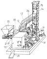
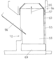
この発明の燃焼炉10は、内槽63と外壁64の間に間隙65を設け、矢示66のように吹き上げられた灰が、内槽63と、外壁64の間隙65を矢示67のように通過し、下方へ落下して灰室68へ溜まるようにしてある。灰室68の底板69は金属製であって、灰は比較的急速に冷却される(図10)。
In the
またロストル1に突出部1aを設け、突出部1a内に電極4、4を貫通設置してあるので、電極4、4はコークスなどから保護されている。また突出部1aは、図9(b)のように菱形をなしており、矢示70の方向から供給されるコークス3がスムースに送入されるようになっている。
Moreover, since the protrusion 1a is provided in the
1 ロストル
2 ロストル蓋
3 コークス
4 電極
6 炉体
7 生ごみ
8、9 触媒層
10 燃焼炉
11 排気路
12 第1の熱交換器
13 冷却装置
14 活性炭層
15 シリカゲル層
16 タービン
17 煉瓦工場
18 第2の熱交換器
20 生ごみホッパー
21 ロータリーキルン
30 分離器
DESCRIPTION OF
Claims (11)
Priority Applications (1)
| Application Number | Priority Date | Filing Date | Title |
|---|---|---|---|
| JP2004105294A JP2005291590A (en) | 2004-03-31 | 2004-03-31 | Ultra-high temperature flame generating method, ultra-high temperature combustion furnace, garbage incinerator, and flue gas cooling device |
Applications Claiming Priority (1)
| Application Number | Priority Date | Filing Date | Title |
|---|---|---|---|
| JP2004105294A JP2005291590A (en) | 2004-03-31 | 2004-03-31 | Ultra-high temperature flame generating method, ultra-high temperature combustion furnace, garbage incinerator, and flue gas cooling device |
Publications (1)
| Publication Number | Publication Date |
|---|---|
| JP2005291590A true JP2005291590A (en) | 2005-10-20 |
Family
ID=35324712
Family Applications (1)
| Application Number | Title | Priority Date | Filing Date |
|---|---|---|---|
| JP2004105294A Pending JP2005291590A (en) | 2004-03-31 | 2004-03-31 | Ultra-high temperature flame generating method, ultra-high temperature combustion furnace, garbage incinerator, and flue gas cooling device |
Country Status (1)
| Country | Link |
|---|---|
| JP (1) | JP2005291590A (en) |
Cited By (2)
| Publication number | Priority date | Publication date | Assignee | Title |
|---|---|---|---|---|
| CN115654497A (en) * | 2022-11-01 | 2023-01-31 | 中国空气动力研究与发展中心设备设计与测试技术研究所 | Method for building ultra-high temperature stable laminar combustion environment |
| CN117346146A (en) * | 2023-12-04 | 2024-01-05 | 山西三水能源股份有限公司 | Biomass auxiliary type garbage pyrolysis equipment |
-
2004
- 2004-03-31 JP JP2004105294A patent/JP2005291590A/en active Pending
Cited By (4)
| Publication number | Priority date | Publication date | Assignee | Title |
|---|---|---|---|---|
| CN115654497A (en) * | 2022-11-01 | 2023-01-31 | 中国空气动力研究与发展中心设备设计与测试技术研究所 | Method for building ultra-high temperature stable laminar combustion environment |
| CN115654497B (en) * | 2022-11-01 | 2023-09-08 | 中国空气动力研究与发展中心设备设计与测试技术研究所 | Construction method of ultra-high temperature stable laminar flow combustion environment |
| CN117346146A (en) * | 2023-12-04 | 2024-01-05 | 山西三水能源股份有限公司 | Biomass auxiliary type garbage pyrolysis equipment |
| CN117346146B (en) * | 2023-12-04 | 2024-02-13 | 山西三水能源股份有限公司 | Biomass auxiliary type garbage pyrolysis equipment |
Similar Documents
| Publication | Publication Date | Title |
|---|---|---|
| CN204006025U (en) | A kind of dangerous waste and medical waste incinerator complexes | |
| CN103438461B (en) | A kind of integral type pyrolysis restoring system and waste disposal method | |
| CN103557526A (en) | Complete equipment of hazardous waste and medical waste incinerator and incineration method of hazardous waste and medical waste | |
| JP4382470B2 (en) | Waste pyrolysis treatment equipment | |
| JP2011196598A (en) | Method of supplying combustion air in vertical waste incinerator, and vertical waste incinerator | |
| CN204063061U (en) | A kind of plasma furnace for the treatment of domestic waste incineration flue gas | |
| CN207893761U (en) | A kind of dangerous waste incineration processing system | |
| CN104006390B (en) | A kind of method of cement plant cooperative disposal garbage power | |
| JP2003279013A (en) | Waste gasification and melting system | |
| CN108518693A (en) | Hazardous solid waste plasma innocuity disposal system and method | |
| JP2009139087A (en) | Control method of waste thermal decomposition apparatus | |
| JP2001342476A (en) | Garbage carbide production method and production equipment | |
| CN107726325A (en) | Melting equipment for treating waste and waste treatment method | |
| JP3957737B1 (en) | Combustion system for flame-retardant high-viscosity waste such as PCB | |
| CN107676796A (en) | A kind of oxygen-enriched burning of dewatered sludge and cement kiln synergic processing device of sludge and method | |
| JP2005291590A (en) | Ultra-high temperature flame generating method, ultra-high temperature combustion furnace, garbage incinerator, and flue gas cooling device | |
| RU91409U1 (en) | INSTALLATION FOR THERMAL PROCESSING OF SOLID DOMESTIC WASTE | |
| CN104728846A (en) | Rotating dual-roller incinerator | |
| CN214198674U (en) | Industrial waste classified incineration system | |
| JP3844327B2 (en) | Method and apparatus for processing radioactive graphite | |
| JP4918185B1 (en) | Hybrid incinerator system | |
| JP2002195519A (en) | Waste gasification and melting method and apparatus | |
| CN112050220A (en) | A processing system and method for purifying stale garbage using plasma technology | |
| JPH0712321A (en) | Combustion discharged gas toxic substance thermal decomposition furnace | |
| CN119755637B (en) | Chemical waste salt incineration disposal and resource utilization device and method |